

Page 1
OPERATION AND SERVlCE
MANUAL
ROD-L
M25
25
AMP
GROUND CONTINUITY
TESTER
JULY,
1984
Advanced Test Equipment Rentals
www.atecorp.com 800-404-ATEC (2832)
®
E
s
t
a
b
l
i
s
h
e
d
1
9
8
1
Page 2
TABLE OF CONTENTS
-
SECTION
I
INTRODUCTION
1-1
General
1-6 General Description
1-11
Equipment Supplied
1-15 Identification
1-17 Specification
I1 INSTALLATION AND OPERATION
General 2-1
Unpacking and Inspection 2-1
Installation 2-1
Rack Mounting 2-1
Power Requirements 2-3
Power Cable 2-3
Initial Installation and Turn On
2-3
Storage 2-3
Repackaging for Shipment 2-3
Operating Controls 2-4
Operational Check 2-8
Test Time Adjustment Procedure
2-1 0
Automatic Test Procedures 2-1 0
25AMP Ground Tester with M488 Tester
Set
Up 2-10
ill
THEORY OF OPERATION
3-1 Theory of High Current Ground Testing 3-1
3-2 Ground Continuity 3-1
3-3 Instrument Functional Diagram 3-3
3-6 Instrument Assembly Diagram 3-4
3-7 Power Supply Circuit
(A101 3-4
3-9 A22 Control Logic Board 3-4
IV MAINTENANCE AND SERVICE
Introduction
Calibration
Set Up
Meter Mechanical Zero
Ammeter Calibration
Fail Pots Calibration
Test Time Calibration
Resistance Calibration
Troubleshooting
Page 3
SECTION
TABLES, SPECIFICATION CHAR'TS
AND
DIAGRAMS
Table
1-1
Figure 2-1
Table 2-1
Figure 2-2
Figure 2-3
Figure 3-1
Figure 3-2
Figure 3-3
Table 4-1
Figure 4-1
V
PARTS LIST
Specifications
Rack Mounting Kit Installation
Control And Indicators
Control And Indicators
M25
Hipot Interface
Functional Diagram
Assembly Diagram
Detail Functional Diagram
Calibration Equipment
Test Set-Up
A10 Power Supply
A22 Control Logic
VI
SCHEMATICS
Wiring Diagram
Assembly Drawing, Mother Board
A10 Power Supply
A10 Power Supply Assembly
A22 Control Logic
A22 Control Logic Assembly
W
OPTIONS
PAGE
1-2
2-2
2-5
2-7
2-1
1
3-3
3-4
3-5
4-1
4-3
5-2
5-3
A8 Remote Control
Parts List
Schematics
Page 4
lNTRODUCrI'lON
SECTION
I
1-1
GENERAL
1-2 This publication, which provides operating and servicing instructions for
the ROD-L Electronics 25 amp Ground Testers is divided into five sections.
sections I describes the Instrument and list its specifications. Section
II
contains Installation Instructions and Operating Procedures. Section 111
contains Theory of Operation. Section IV contains Service and Calibration
Instructions. Section
V
contains Replacement Parts Information, Parts
Location Diagrams and Schematics.
1-3 25amp Ground Testers are Low Voltage testers with ground continuity
test capability for performance of ground tests in accordance with
applicable B.S.I., V.D.E. and I.E.C. standards.
1-4 The 25 amp ground test is one of many tests required by certification
agencies
as
proof of an instrument's ability to withstand power line
spikes without becoming a hazard to itself or the user. For example,
lighting, drastic load changes or power line outages can place short
duration spikes on power lines of many times nominal line voltage. The
gnd should be able to divert any leakage to the chassis without getting
damaged.
1-5 GENERAL DESCRIPTION
1-6 The ROD-L Model
25amp Ground Testers apply low voltage to the device
under
test
for a duration of time preset from one second to
90
seconds.
The device under test is plugged into the front panel receptacle (or special
rear panel connector on some models). Test limits for total resistance
are preset by the user via a rear panel control. When the device under
test is defective, automatic circuitry turns off the low voltage and meter,
lights the FAIL lamp and activates an audible alarm. These audible and
visual alarms must be manually reset at front panel or can be reset by
remote control (see options).
1-7
All
Models incorporate a rapid, automatic electronic shutdown circuit to
turn off the low voltage within two milliseconds after a fault.
1-8 For operator use, the test cycle is
fully automatic; accidental test
initiation is prevented by use of a recessed start switch. If ground fails
during the test, the Tester automatically activates failure operation, i.e.,
voltage is shut down and there is a visual and audible alarm.
Page 5
1-9
The ROD-L 25 amp Ground Testers are completely self contained
rugged instruments designed for laboratory and production testing
environments.
1-1
0
EQUIPMENT SUPPLIED
1-11
The ROD-L Ground Tester is comprised of the following:
a.
Ground Tester, ROD-L Model 25amp Ground.
b. Six foot power cord, three pronged.
c.
18 inch Ground Cable
d. This Manual
e.
Extra fuses
f. HV Interface Cable
1-1
3
The ROD-L 25amp Ground Testers are identified by a part number
and
a
serial number (see Figure 2-2).
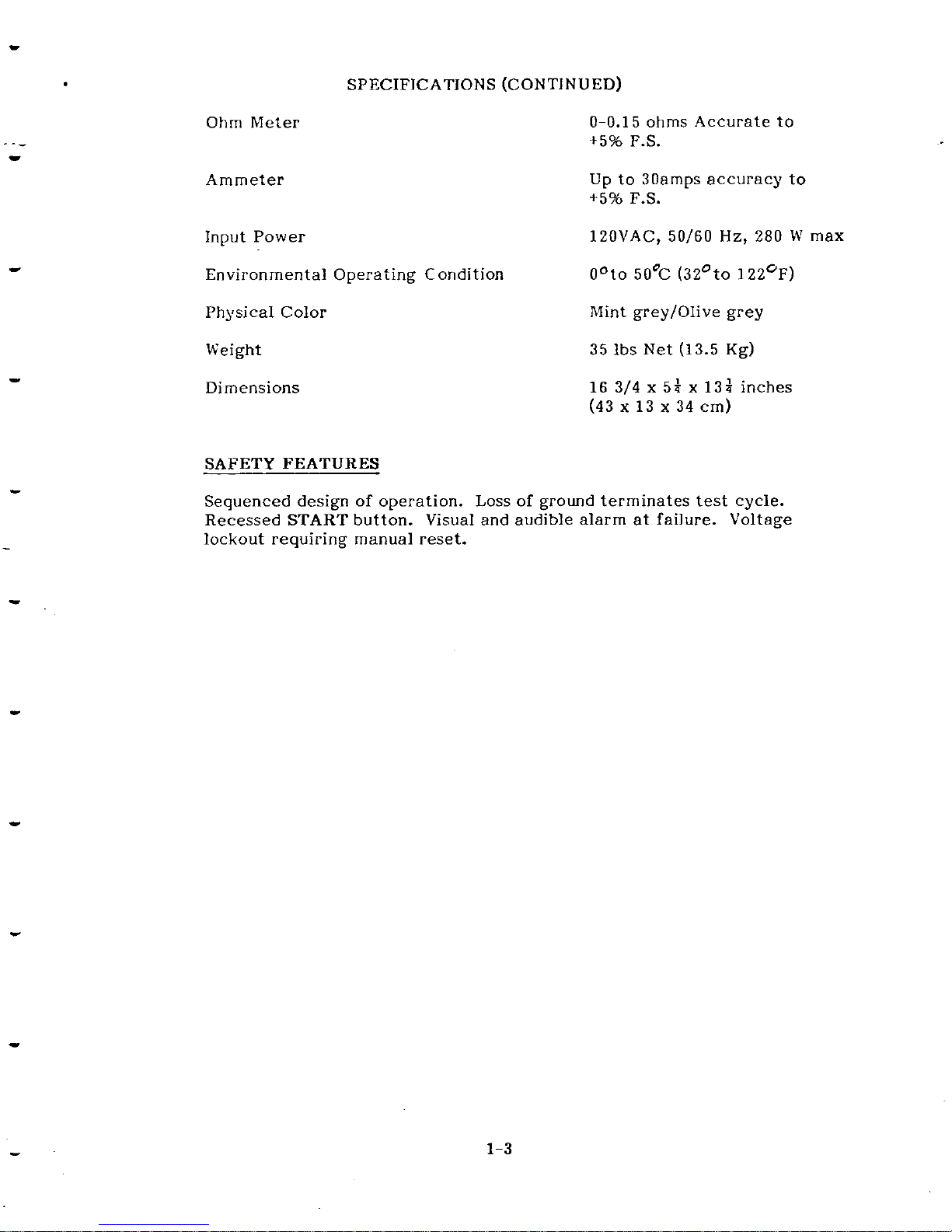
Table
1-1
lists the most important electrical, environmental and
physical specifications of the Ground Testers.
TABLE
1-1
SPECIFICATIONS
Test Voltage and Current
Voltage Shutdown
Automatic Test Cycle
Initial Turn
-
On Period
3
VAC RMS, 25 ARMS,
33/60
Hz
at
0.1 ohms load
.
No Load boltage, YVACRMS.
Within 2ms after a fault
(electronic shutdown circuits).
One second to 90 seconds
Allow
5
minutes warm-up
Page 6
Ohm Meter
Ammeter
SPECIFICATIONS (CONTINUED)
0-0.1 5 ohms Accurate to
+5%
F.S.
Up
to 30amps accuracy
to
+5%
F.S.
Input Power
lZOVAC, 50160
Hz,
280 W max
Environmental Operating Condition O"to 50% (32Oto 122*~)
Physical Color Mint greyIOlive grey
Weight 35
ibs Net (13.5 Kg)
Dimensions
SAFETY FEATURES
16 3/4x54x13i inches
(43
x
13 x 34 cm)
Sequenced design of operation. Loss of ground terminates
test
cycle.
Recessed
START
button. Visual and audible alarm
at
failure. Voltage
lockout requiring manual reset.
Page 7
INSTALLATJON AND OPERATJON
SECTION
I1
2-1 GENERAL
2-2
This section contains
the
recommended procedure for unpacking and
inspection, installation, operation, storage and reshipment.
2-3 UNPACKING AND INSPECTION
2-4
Any shipping carton that appears damaged should be unpacked with
carrier's agent present. Inspect the instrument for damage (scratches,
dents, broken knobs or meters, etc). If the instrument is damaged
or
fails to meet specifications (see Performance Test, Section IV), notify
ROD-L Electronics immediately, retain the shipping carton and the
padding material for the carrier's inspection.
2-5 LNSTALLATION
2-6
The ROD-L Model
25amp Ground Testers
are
suitable for either bench
or rack mounting. To rack mount the instrument, use Rack Mounting
Kit, part #M100-5001.
Rack Mounting Kits may be ordered from factory.
2-7
RACK
MOUNTING
2-8
The procedure for installing Rack Mounting Kit, M100-5001 on the
Tester
is
as
follows:
a.
Place the instrument on edge of bench
as
shown in Figure
2-1
b.
Remove Trim Strip (#2) from both sides of instrument
c.
Place L-Bracket
(#3)
and secure to chassis with two machine
screws
(#4)
furnished with Mounting Kit.
d.
Rotate Instrument on work bench and repeat steps "b" and
nC~~
.
Check that screws and brackets are firmly secure
Page 8
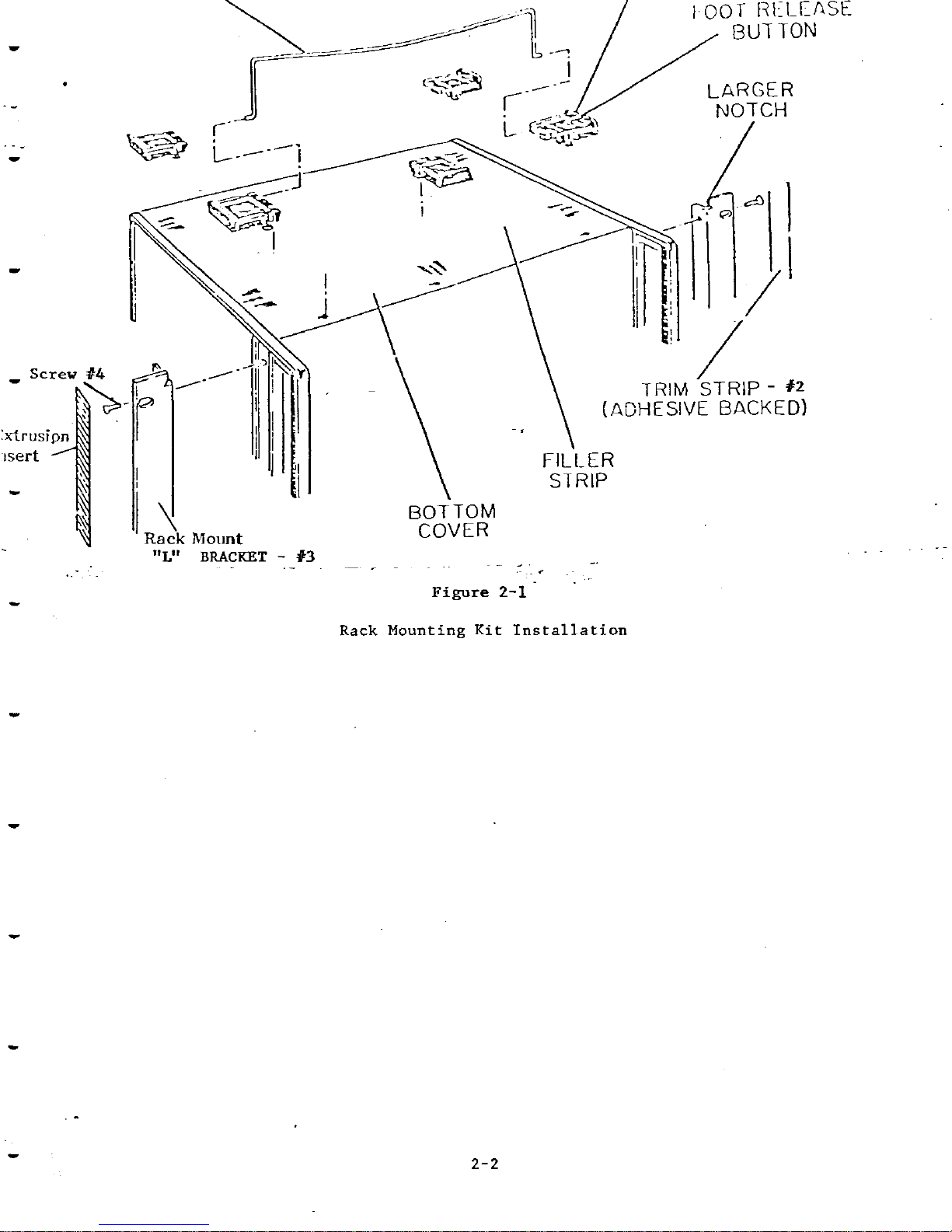
Figure
2-1
-
Rack
Mounting Kit Installation
-
Page 9
2-9 POWER REQUIREMENTS
2-10
The Model 25amp Ground Tester requires a power source of 120 or 240
volts AC, single phase, 50 to 60
Hz.
Insure that the power socket to
which the instrument connects has a functioning safety ground.
2-11 POWER CABLE
2-12
To protect operating personnel, the National Electrical
Nanufacturers
Association (NEMA) recommends that the instrument panel and cabinet
be grounded. This instrument is equipped with a three-conductor Dower
cable which when plugged into an appropriate.rcceptacle grounds the
instrument. The offset pin on the three-prong connector is the ground
pin.
2-13
INITIAL INSTALLATION AND TURNqN
2-14 CAUTION
Prior to applying power to the instrument perform the following:
a.
Turn-Off Power Switch on ROD-L Tester,
set
the rear panel
AC Line 115/230V voltage switch to indicate the number that
corresponds to the line voltage range being used. The number
visible on the slide switch indicates the line voltage range for
which the primary circuit is connected.
Set the OHMS TRIP control to full clockwise position.
With and AC voltmeter, check the primary power line for normal
line voltage conditions.
Set VOLTAGE ADJ switch on rear panel to appropriate position
ke.
if input low line conditions exist, set to normal,8% low line,
or 16% low line as appropriate).
e.
With power switch off, check to be sure that the proper fuses are
installed in accordance with markings on rear panel and in accorance with 115/230V line switch.
f.
Connect the six foot power cord between instrument and power
source. Operational Check procedure per paragraph 2-23.
2-15 STORAGE
2-16 It is strongly recommended that the equipment be packed as if for
Page 10

reshipment. Environmental conditions during storage and reshipment
should be as follows:
a.
Maximum temperature
167 degrees F(75 degrees
C)
b. Minimum temperature
-40
degrees F
(-40
degrees
C)
2-17 REPACKAGING FOR SHIPMENT
2-18
If possible, use the original shipping container and packing materials,
or:
a. Wrap the instrument in heavy paper or plastic before placing
it
in the shipping container.
b. Use plenty of packing material around the instrument and
protect the front panel with cardboard or plastic bubble
packing. Protect the instrument with two inch rubberized
foam pads placed along
all
surfaces of instruments, or with
a
layer of excelsior about six inches thick packed firmly against
all
surfaces of instrument.
c.
Use a strong, well-sealed shipping container (350 lb/sq in.
bursting test).
d.
Mark the container "FRAGILE
-
DELICATE INSTRUMENT!'
2-19
Attach
a
tag to the instrument giving the following information:
a.
Type of service required.
b.
'
Return address
c.
Instrument Model number
d. Full Serial Number
In any correspondence refer to the instrument by Model number and
full serial number.
2-20 OPERATING CONTROLS
2-21
Figure 2-2 illustrates the front and rear panel controls for the
Model
25amp Ground Testers Table 2-1 describes the functions of all the controls
and indicators.
Page 11
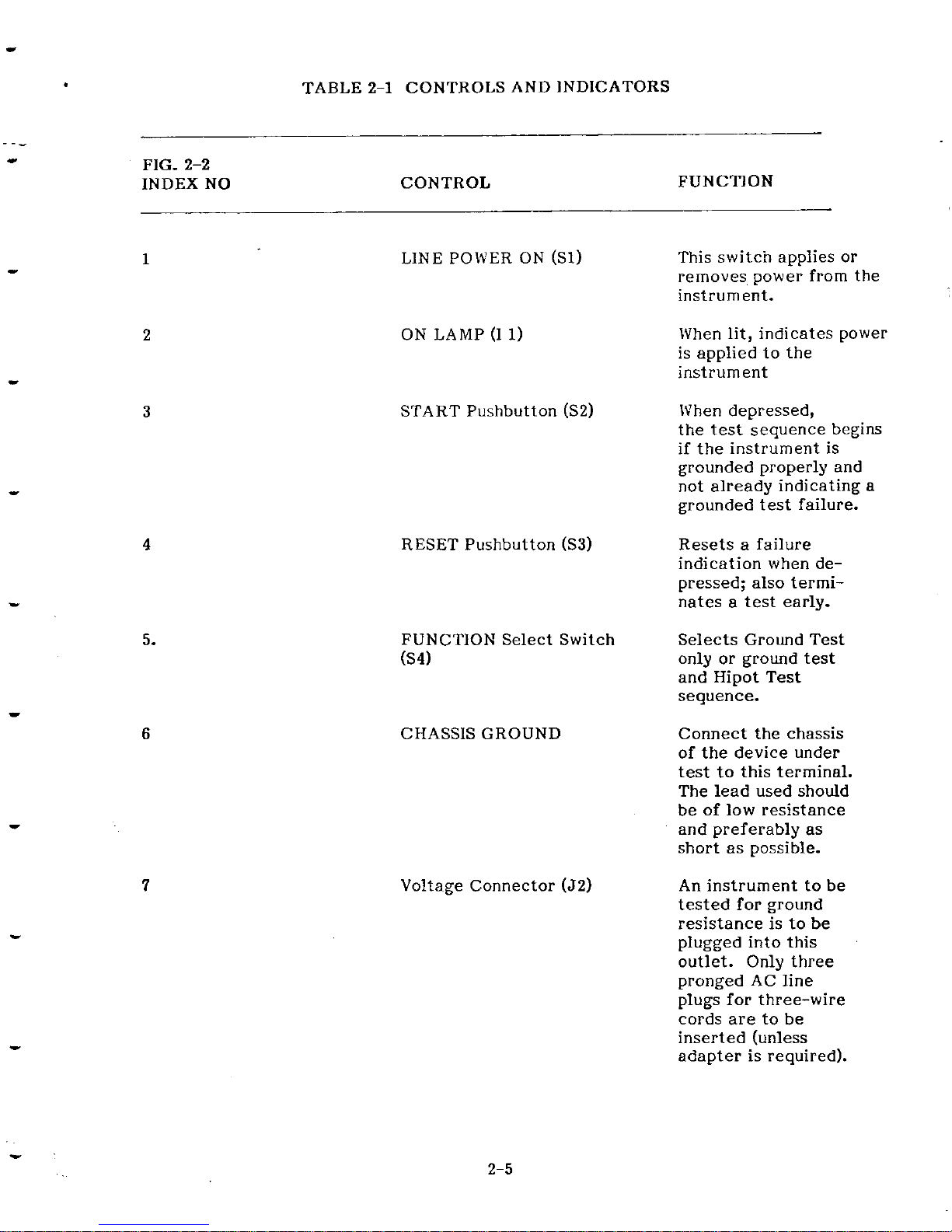
FIG. 2-2
INDEX
NO
TABLE 2-1 CONTROLS AND INDICATORS
CONTROL
LlNE POWER ON (Sl)
ON LAMP (1
1)
START Pushbutton (S2)
RESET Pushbutton (S3)
FUNCTION Select Switch
64)
CHASSIS GROUND
Voltage Connector (52)
~-
-
FUNCTION
This switch applies or
removes, power from the
instrument.
When lit, indicates power
is applied to the
instrument
When depressed,
the
test
sequence begins
if the instrument is
grounded properly and
not already indicating a
grounded test failure.
Resets
a
failure
indication when depressed; also terrninates
a
test early.
Selects Ground Test
only or ground
test
and Hipot Test
sequence.
Connect the chassis
of the device under
test
to this terminal.
The lead used should
be of low resistance
and preferably
as
short as possible.
An
instrument to be
tested for ground
resistance is to be
plugged into this
outlet. Only three
pronged AC line
plugs for three-wire
cords are to be
inserted (unless
adapter is required).
Page 12

TABLE 2-1 CONTROLS AND INDICATORS (continued)
FIG.
2-2
INDEX NO CONTROL FUNCTION
Ohms Meter (RMeter)
Total Current Meter
(
I
METER)
FAIL Indicator
(14)
TESTING Indicator (I
3)
READY Indicator (I 2)
Audible Warning (SP1)
AC Line Voltage (A71
AC Line power receptable (J1)
Line Fuse (F2)
Line Supply Fuse (El)
Ohms Trip Pot (R5)
Low Line Switch (S5)
Serial/Model Code Label
Remote Control Connector(J3)
Hipot Interface Connector (54)
2-6
Provides
a
direct reading of
the Resistance of
the
tested
instruments ground loop.
Indicates amount of AC
current in (AMPS) flow
during a test.
Displays a visual warning
that
test
was a failure.
Indicates
a
test
in progress.
Comes on a power up.
Emits
a
warning sound
when a test results in
a
failure.
Slide switch to select
either 115 VAC or
230
VAC.
The exposed number
indicates the Line Voltage
range
selected.
Connects to power cable
supplied with instrument.
Provide primary circuit
protection from overcurrent conditions.
SAME AS ABOVE
Calibrates Ohms Trip setting.
Compensate for input Low
Line Voltage conditionnormal,
-8%,
and -16%.
Identifies Serial Number and
Model number of
tester.
Allows Remote signal
input and output.
Allows interface with ROD-L
~ii'pot tester.
Page 13

Rear panel
jack
for
chassis
Gnd sense from ROD-L
Hipot
Tester.
Figure
2-2
Controls
and
Indicators
Page 14

2-22
OPERATlONAL CHECK (25 AMP GROUND TESTER ONLY)
1.
Check line voltage at outlet. Set rear panel voltage select
switch to closest Line Voltage Range.
2.
Connect 25 amp Ground Tester to Power outlet.
3.
Turn AC On Switch to
ON.
a.
AC on Lamp should light
b. READY lamp should light
4.
Insert 25amp banana plug cord into chassis ground plug.
Connect 25amp clamp to any exposed metal part of the
ground tester.
5.
Insure that "OHM Trip" on rear panel is
set
to Maximum "10".
6.
Depress START button:
a.
Testing Lamp should come on for approximately 5
seconds.
b.
Current Meter should read approximately
30A.
C.
OHM Meter should read approximately
.005
OHMS
(Record this reading)
7.
Set
"Total OHM Trip" pot to minimum
"0".
a.
Depress START button.
1.
Sonalert should sound
2.
Red FAIL lamp should come on
b. Depress RESET
1.
Sonalert should go off
2.
Red FAIL lamp should go off
If the above conditions are met the 25amp ground tester is operating
properly and is ready for use. If your normal operating voltage
is
different from the specified refer to SET-UP procedure (4-5);
8.
Total Resistance Trip Set
a.
BSI Standard states that the resistance to be measured
shall not exceed (0.1
+
R) OHMS, where R is the resistance of the supply cord. The 25amp grounding cable
must also be considered, this resistance was measured
in step 6C.
Page 15

b.
Each division on the scale of the total current trip
pot represents approximately .015 OHMS. Thus
a
dial setting of 7..0 would fail all devices under test
with
a total resistance of .105. A dial setting 9.0
would fail a resistance of .I35 OHMS.
c.
For more accurate failure points, a known value of
resistance may be inserted in the loop and the trip
point adjusted until a failure is indicated.
9.
GROUND TEST
Plug power cord of device under test into the three
pronged receptacle on the front panel of the
25amp
ground tester.
Connect 25amp banana plug into banana jack (chassis
ground) on front panel of tester.
Connect 25amp clamp to exposed metal part of chassis
of device under test. Make sure connections are solid.
Depress START
Testing Light should come on
If the total resistance of the device under test does not
exceed setting of trip pot, test will run approximately
five seconds.
The Ammeter will indicate current thru the Ground Loop.
The
OHM
meter will indicate the resistance of the
ground loop of the device under test.
If the total resistance of the device under test is higher
than the Trip pot setting
a
failure indication will be
given (Audible
&
Visual).
To test devices that do not have a three pronged supply
cable, the user can make a suitable grounding cable by
using three (3) layers of Beldon 8660 3/16" flat tinned
copper braid and
(2)
Mueller #24a 25amp clamps. To
perform a ground test under these conditions:
a.
Connect banana plug to tester banana jack.
b.
Connect clarnp to the chassis of the device
under test.
c.
Connect one clamp of new cable made per above
.
to device under test and other clamp to 25amp
tester chassis. Proceed with Step 9d. (Remember
to compensate Trip point for resistance of the
newly made cable).
Page 16

2-23 TEST
TIME
ADJUSThlENT PROCEDURE
2-24 The Test Time Adjustment potentiometer is factory set for 5-7 seconds.
The user should reset this control as necessary in accordance with the
regulatory agency suggested test time for the device under test. To
reset the test time duration, proceed as follows:
a.
Turn
OFF
power to M25
b. Remove top cover and locate Test Time Adjustment potentiometer
"R22" on board A22.
c.
Reapply power to
25amp Ground Tester.
d.
With
top cover removed test a device for ground resistance using
a stopwatch, time the duration the TESTING lamp remains lit.
By adjusting the 'TEST Time Adjustment
trimpot and timing the
TESTING lamp duration with the stopwatch, you should be able
to set any duration desired between one second and
90
seconds.
CAUTION
Do not touch any of the other potentiometers on
the PC boards, otherwise the calibration of the
instrument will be destroyed.
2-25
AUTOMATIC TEST PROCEDURES
The ground tester and hipot tester should be stacked with ground tester
on top. (see Figure 2-3)
Connect remote control cable (25 pin connector) to ground tester and
remote operating device (Figure
3)
if Tester is equipped with option
#01.
Connect ground tester hipot interface cable (4 pin LGH connector) to
hipot and ground tester set.
Connect ground tester and hipot tester to the same AC Line Power source.
Turn AC power switch of ground tester on first*.
Turn AC power switch of hipot tester
ON.
*If Hipot is turned on first, Hipot tester may immediately start test when
ground tester is turned on and high voltage will appear on both output
receptacles.
Device to be tested should be plugged into ground tester receptacle for
sequential testing,
i.e., 25amp test first and then Hipot test.
Page 17

Put front panel switch in Ground/HP position for sequential testing. If
ground test only is performed ?laced switch in ground position.
Sequential testing or ground only test will be initiated
by
starting ground
tester. Hipot tester's chassis Gnd voltage must connect to BP-2 Rear
Panel Banana Jack.
If Hipot test only is preferred, test must be initiated at Hipot tester.
A
failure of ground test will not allow Hipot test to start.
If
failure occurs in ground test or Hipot test a reset must be initiated
before any further testing. If failure occurs in Hipot test only, tester
will automatically reset in
3
seconds if tester is equipped with automatic
reset option. The Gnd Tester reset also resets the Hipo Tester.
If the Hipo tester's chassis Gnd voltage is not connected to BP-2 rear
panel Banana Jack, the READY light of the Hipo Tester should be
OFF
and no Hipo Test can be initiated from the Gnd Tester.
If the Hipo
Tester's chassis Gnd voltage is connected to BP-2, the total safety Gnd
return from the device under test up to the Hipo Tester is tested and the
READY light should be on if the total resistance presented is less than
the required
(0.5
ohms standard). It is assumed that the Hipo tester
controls are already set up according to the respective operations
Manual.
Ground Tester to
Hipot Interface Connector
Remote Control
Connector
Gnd
Tester
USER
Supplied
To Remote
HIPOT
TESTER
Control
Unit
Powe
Variac
25
AMP
GROUND
CONTINUITY
TESTER/HIPOT
INTERFACE
Figure 2-3
2-1
1
Page 18

PUSH START BUTTON
1. The READY light of the Hipo Tester should go off since the safety
Gnd return test from the device under test is taken over by the
M25
Gnd tester using the relays K1 and
K2
(see Dwg. #00431-01).
The safety Gnd return is connected to the Gnd tester chassis and
the chassis Gnd voltage output thru BP-1 is connected to the High
Current Transformer.
2. The test light of the
M25
comes
ON
and the Gnd test is performed.
Should a failure occur the
M25
has to be manually reset and no
Hipotester will be automatically started if that occurs.
3.
If
the test performs successfully the TEST light should go
OFF
after the preset time and the READY light in the Hipotester should
go
ON
since the Hipotester is now taking over the safety Ground
Return Test when the relays K1 and
K2
in the
M25
return to normal
position, that is, connecting the safety Gnd return to the Hipotester
chassis through HV return wire and connecting the chassis Gnd
voltage output BP-1 to BP-2 where the chassis Gnd voltage of the
Hipotester is connected to.
4.
After about one second the Hipotester is started automatically from
the
M25.
The test light of the Hipotester should come on. The
Hipotester should perform as specified in the respective Manual.
The M25 can at any given moment
of
time reset the Hipotester by
manually depressing the RESET button on the M25.
2-27
25AMP
GROUND TESTER
WITH
M488
TESTER SET
UP
The ground tester and hipot tester should be stacked with ground on top
as described before. The ground tester hipot interface cable, and the
connection between the M488's chassis Gnd voltage and the Bp-2 rear
Panel Banana Jack of
M25,
should be made in the same way as described
before.
The M25 should be equipped with option #01 Remote Control Board and
the Remote control cable
(25
pin connector) must connect to both the
M25
and the M488.
Turn AC power switch of M488
ON
first.
Turn AC power switch of M25
ON.
Device to be tested should be plugged into M25 receptacle for sequential
testing, i.e., 25amp test first and then hipot test. Ground only test will
be initiated by starting the ground tester.
Sequential testing will be initiated by starting the M488 Hipotester
according to the instructions described in the
M488
operations Manual.
The Remote Board should be adjusted
if
needed for giving out 10 VDC
when a 0.1 ohm load resistor is used,for monitoring the resistance
valve in the
M488
side.
Refer to Options Section
VI.
Page 19

THEORY OF OPERATION SECTION
m
THEORY OF HIGH CURRENT GROUND TESTING
Three production line tests are required by most regular agencies.
These basic stept are
rounding
continuity, dielectric strength, and
leakage current.
3-2
GROUNDING CONTINUITY
The grounding of a product is one of the basic methods of protection
required by both international and domestic safety agencies. Grounding
is considered to be the second level of protection in a two-level system.
The first level is the reliability of the functional insulation system and
the second level is the grounding of all
operator-acce~sible dead-metal
parts.
In the event of
an
insulation failure, hazardous levels of voltage and
current are shunted away through the grounding conductor to the
"earth" ground point or the service ground. The reliability and the
capacity of the grounding connector and the grounding systems should
be capable of handling the most severe fault conditions.
In addition to safety of personnel and property, there is another
benefit of the grounding system. The system shunts away to "earth"
electrostatic charges and induced electromagnetic "eddy" currents
from stray fields. The grounding system is an aid to preclude the
malfunctioning of the logic and microelectronic circuits; that is,
.
it assures the proper functioning of the product. Grounding coupled
with
EMC
protective devices can reduce hazards to the customer
and product.
Prototype testing for grounding was instituted in order to assure the
inherent safety of the design of the grounding system. Type testing
is
a
design tool in that it proves the validity of the basic design. It
also established one essential aspect of reliability, namely, the current
carrying capacity of the system should a fault occur. This is accomplished by the test current amplitude which is sufficiently high to
effectively "burn out" weak spots as well as by the actual resistivity
measurement to assure
a
sound path for current flow to ground.
Production line testing assures the continuity of the grounding system
and the continuance of the good basic design. Production line tests
can detect latent defects in workmanship, insulation materials, conductor
size, and grounding connections. By applying the ground continuity
test on the production line, each unit or product is tested for the
absence of the vital second level of safety protection. The lack of
which may be a substantial safety hazard. Production line tests are
performed for customer safety, product reliabiltiy and manufacturer
product liability protection.
Page 20

Grounding continuity tests are also required to assure the safety
and protection of manufacturing personnel during the performance
of subsequent dielectric strength tests and leakage current tests.
The grounding test achieves a two-fold purpose:
(1)
It assures the
satisfactory completion of subsequent tests, and
(2)
assures that
the second test can be accomplished witl~out undue hazard to the
test operator. If grounding continuity were interrupted at any point,
the dielectric strength test between the internal circuitry and the
ungrounded segment would not be adequately tested
if,
in fact, there
was any electrical stress applied to the associated insulation.
Similarly, if the grounding conductor were not contiguous to all
"deal netal" parts of the product, the detectable leakage current
would be substantially less; where in fact, the hazard is significant.
If the test operator should come in accidental contact with an
"ungrounded" part, it is possible the operator may become the
faultcurrent path to the earth ground point or service ground. For dielectric strength tests, it could be a high voltage injury. For leakage
current, it could be a hazardous energy surge. Consequently, the
application of the grounding continuity test is not only essential
for accurate test results, but also very essential for protection of
test personnel.
Page 21

3-3
INSTRUMENT FUNCTIONAL DIAGRAM
Functionally, the GND tester is divided into three sections: The
High Current generator and the General Control.
A
remote
control option can be added to the total system (as shown in
Fig.
3-2).
3-4
The High Current generator consist of an AC transformer
(50160
Hz) specially designed to provide the current needed in the
ground test.
It
is activated through a solid state optical isolated
relay during an AC input line zero crossing after the correspondent
signal is given by the General Control.
3-5
The General Control performs the coordination of the different
activities and monitoring as shown in Fig.
3-1.
Start
Reset
\=dpc~dy
Light
Resistance Sense Fail
Current Sense MI, R Meter
Resistance Trip Start Test
I
Close Relays
[
HIPO
Interface
Fig.
3-1
Functional Diagram
General Control
Front. General High Current High
And Control Generator Current
Rear
Panel Control
Front
Panel
Indicators
Remote
Control
Option
Remote
Controller
R
Output
v.
Interface
Page 22

The General Control can be commanded from the different front
and rear panel controls shown on the left side of the diagram. It
takes care of coordinating the different activities and sensing the
status of the operation. It provides continuous monitoring through
the front panel lights, buzzer and meters shown on the right side of
the diagram.
The remote option is an isolated interface for most of the control
and monitor signals.
3-6 INSTRUMENT ASSEMBLY DIAGRAM
The left side subassembly is physically separated and contains
a
Mother Board, Control Logic and Power Supply Board and eventually the Remote Control Board as an option. The right side subassemblies contains the electrical transformers, relays and
current sense resistors.
The instrument is divided in two major subassemblies as shown in
Fig. 3-3.
r-------
HV
Transformer
1
I
Power Supply TransF.
Control
I
I
I
Mother
I
Solid State Relay
I
A more detailed diagram of the functions is shown in Fig. 3-4.
Board Power
I
I
3-7 POWER SUPPLY CIRCUIT (A10)
Electromechanical Relays
I
I
Current Sense Resistors
]
1
3-8
The bias generated in the A10 assembly board consists of +15VDC
and -15VDC for the analog circuits. The digital electronics requires
+5VDC regulated. As seen in the squematic (DWG. 00459-01 Rev A).
L
-------
A
Fig. 3-2 Assembly Diagram
The different AC voltages are full wave rectified by
U1,
2
and 3,
filtered and regulated byUR1,
2
and 3.
3-9 A22 CONTROL LOGIC BOARD
Page 23

3-10
TOTAL CURRENT DETECTOR
The A22 Board (Dwg. 446-01) receives the voltage across the current
sense resistor set composed
of
8
resistors
of
2ohm
5011'
each giving
a
total resistance of 0.25 ohm.
RESISTORS
I
I
SOLID
-HIGH
CURRENT--
RELAY
I
I
>HIGH
CURRENT
I
STATE TRANSFORMER
RELAY
OUTPUT
-
-
FRONT AND
REAR PANEL
CONTROL
FRONT PANEL
INDlCATORS
Interface
ANALOG
DIGITAL
CONTROL
+5V +15V -15V
GND
1-1-
11,
I
POWER SUPPLY
I
I
BOARD
I
-
Fig.
3-3
DETAIL FUNCTIONAL DIAGRAM
Page 24

3-1
2
PROVISION FOR FUTURE REMOTE PROGRAMMING
The remote signal
at
pin C of the edge connector can activate the
transistor
Q2
when no remote programming is desired, connecting
pin C of the edge connector to +5V. This will put
a
low level
at
pin 6 of U3 (contact C) and a high level at pin
12
of V3 (contact
D), closing contact
D
and opening contact
C.
The opposite
situation occurs when the pin C of the edge connector is tied to
ground, selecting remote programming.
LOGIC CONTROL
3-14
The assembly receives all push button inputs and sense output from
the fail comparator. The duration of the
test
is set by a timing
circuit. In the event of an operator reset or fail condition, the
test is aborted. If there is
a
failure, a warning is presented until
manually reset by the user. This assembly includes a zero crossing
detector,
a
start generator, a timer, set-reset latches with associated
logic.
3-15
INPUTIOUTPUT LINES
There are three digital inputs: START, RESET and the FAILURE
from the resistance comparator
U9.
There are status an control outputs: TEST LIGHT, REMOTE TEST,
FAIL, ACHIPO START and RESET, RELAYS and an optional pulsing
tone drive output for the buzzer.
An analog input 18 VAC is used to determine the zero crossing of the
AC input line.
STARTLNG
A
TEST
With the start input (pin
9
of the edge connector) two NAND gates
of U5 and
U6
provides a hysteresis buffer and the test latch com-
posed by two NAND gates of
U5
is
set
through pin 13. The output
of the
test
latch (pin 11) drives the transistor Q1 to provide
a
REMOTE TEST signal for the A8 REMOTE BOARD option (as
required by the
11488
instrument interface) and drives through U7
pins
1
and 2 the RELAYS using the pin D
of
the edge connector.
The RELAYS are high current type and as shown in the wiring diagram #00431-01 when they are activated connect the high current
transformer to the
25
ampere output and connect the HV return on
the front panel block to the chassis of the h125 Gnd tester. When
the relays are deactivated the 25 ampere output is connected back
to
1.5 VAC chassis Gnd sense voltage of the AC Hipo tester when
the
M25
is interfaced with
it,
and also connect the Hv return back
to the HV return of the AC Hipo tester. This enable us to perform
during an AC Hipo tester interface operation a continuous chassis
Gnd sense test from the Hipo to the DUT and to have a separate
return for the high voltage test from the DUT to the AC Hipo
tester.
Page 25

The start signal also triggers the DELAY timer U11 for getting the
RELAYS set up and at the end of the delay the START PULSE
timer is triggered. This pulse gates the zero crossing pulses
produced by 98 and trigger the TEST TIMER U11. The output of the
test timer drives the TEST LIGHT through U8 and drives
the
analog
switches in U3 for enabling the monitoring of current and resistance.
The length of the time is controlled by the pot R22.
3-17
FAIL LATCH
The FAIL LATCH can be
set
by the output of the resistance comparator in U9, driving the FAIL signal through U7. The fail latch
is composed by two NAND gates of U6. The latch can be reset by
the RESET signal coming through pin
5
of the edge connector.
3-18 RESET
The fail latch also operates the system reset through pin 2 of
U10.
This gate gathers the different signals that can reset
the system: The reset switch, the fail latch and the test
signal from the test timer.
The
test
signal is fed through
a
network that produces a pulse
at
pin 4 and 5 of U10 at the
end of
test,
resetting
all
the timers and the
test
latch. The
system reset is also transmitted to the AC Hipo Tester when
interfaced through the optical isolator U2.
3-1
9
AC HIP0 START
At the end of successful
test,
the signal from the pin
11
of U5
(the
test
latch) is fed through a network that produces a pulse
at
pin 8 of U12 triggering a delay timer needed for getting the
AC HIPO
set
before a start signal
is
produced by U11. The
delay timer triggers the TRIGGER timer U11 which produces
the
start
signal to the AC HIP0 though the optical isolator
U1.
These timers
are
reset
by the system reset. C22 is larger
than C10 to insure the generation of the AC HIPO START signal
even if the system reset is generated
by
the end of test signal
only.
3-20 OPTIONAL TESTING PULSING TONE
A timer in U12 can be used for generating
a
pulse train signal
to drive the buzzer with Q5 through pin
1
of the edge connector,
when the
test
latch is
set.
This provides a pulsing tone out of
the instrument while we are performing
a
test.
Page 26

MAINTENANCE AND SERVICE
SECTlON
IV
4-1
INTRODUCTlON
4-2
This section provides maintenance and service for the M25 Ground
Tester. Included are: Tables of recommended test equipment,
calibration procedures, Trouble shooting procedures, plus repair
and adjustment data.
4-3
CALIBRATION
4-4
Five major calibration points are required for the
M25
Ground
Tester. They are
:
1.
Meters Mechanical zero
2.
Ammeter Calibration
3.
Resistance Meter Calibration
4.
Test Time Calibration
5.
Fail Pot Calibration
TABLE
No. 4-1
TYPE
AC/DC Digital
Ammeter Volt-
meter (floating
input) RMS
reading
AC Variac
120-240
VACLine
step up trans-
former
MFR
Data Tech Model 31
or equivalent
General Radio
W8MT3VM or
equivalent
USE
General Purpose and
Calibration of Voltmeter and ammeter
AC line Voltage
set-up
2201240 Tests
Page 27

TABLE No 4-1 Continued
Oscilloscope
HP
175 of-equivalent
AC Current American Aerospace
Sensor controls, INC 1003AMI
5 0
0.1 ohm 50W 1%
Dale RH50
Resistor
General Purpose
Ammeter Calib-
ration
Resistance Meter
Calibration
4-5
SET
UP
--
4-6
The equipment should be set up to insure testing
at
120 VAC or
240 VAC plus or minus 1% (low line switch
=
NORMAL). Re-
member to set the line select switch to 115 or 230 VAC position
depending on the AC input line value.
Foreign users or users
where the input line voltage are different from the ones first
described may want to recalibrate on their standard voltage and
frequencies.
4-7
METER MECHANICAL ZERO
4-8
With the M25 turned OFF, note the positions of the current and
resistance meters pointers on the front panel. They should read
zero plus or minus one minor division. If they do not, adjust the
zero
screw.
\
4-9
AMMETER CALIBRATION
4-10
Turn the M25 ON and note that the ammeter position is
at
zero
(plus or minus one minor division). The READY light should be on.
If not, trouble shoot the Power Spply Board or the READY light
driver on the A22 Board. Insure that the calibration load is connected
between the 25A output socket and the
HV
return on the front
panel block (chassis handle could be also used) through the AC
current sense as shown in Fig.
4-1.
Turn the OHMTRIP
potentiometer fully clockwise.
PUSH THE START BUTTON
The ammeter should deflect to about 25 amperes. The
DVM
connected
with the AC current sensor should agree with the ammeter reading
within
3%
of full scale. If they do not, adjust the pot R25 on the A22
Board until they agree within
1%.
See Dwg #00446-02 for pot location.
PUSH RESET BUTTON
Page 28

Page 29

4-1
1
FAIL POTS CALIBRATION
4-1
2
Turn the OHM TRIP potentiomenter fully clockwise. With no load
connected to the M25 output push the START button. The resistance
meter should deflect to full scale and
a
failure mode produced, that
is, constant buzzer sound and FAIL light on. PUSH RESET. Connect
the calibration load to the M25 output as described in section
4-10.
Push the
START
button. While the
test
light is ON, slowly turn
the- OHM
TRIP pot counterclockwise until a failure mode is produced.
PUSH RESET. If
a
max OHM TRIP point wants to be checked, use
0.15 ohms as
a
calibrating load with the OHM TRIP pot fully clockwise.
Push the START button. The resistance meter should deflect to full
scale and a failure mode produced, otherwise adjust R24 on the A22
board counterclockwise until the failure mode is produced. PUSH
RESET and proceed with RESISTANCE CALIBRATION.
4-1
3
TEST TIME CALLBRATION
4-14
Set
a
specific test time per instruction of paragraph 2-24. To check
test
time limits, turn
test
time pot R22 on the A22 board to minimum
(fully clockwise) and maximum. Minimum should be one second and
maximum about 90 seconds. If not, troubleshoot timer or call ROD-L
application Engineer for assistance.
4-1
5
RESISTANCE CALIBRATION
4-16 PUSH THE START BUTTON
The resistance meter should deflect to about
0.1
ohms within
3%
of
full
scale.
If it is not, adjust the pot R21
on the A22 board until it
does deflect up to
0.1
ohms within 1%.
PUSH RESET BUTTON
This procedure is recommended to be done for the resistance tripping
values of the particular application.
4-1
7
TROUBLESHOOTING
4-18 Equipment Required: The required equipment is the same as that
listed in Table No.1.
4-1
9
TROUBLESHOOTING TREE PROBLEM LIST
4-20
The following is
a
list of problems and potential causes.
Page 30

A. NO AC POWER
1.
Check fuses F1 and F2. They might be 3 amperes
slow blow fuses for 120 VAC operation and 2 amperes
slow blow fuses for 240 VAC operation.
RECOMMENDED FUSES:
LI'R'ELFUSE MANUFACTURER
120 VAC
3AG SLO BLO Type 313003
240 VAC 3AG SLO BLO Type 313002
2.
Check for bad AC Power Lamp (]I), ON-OFF switch
(S I), Line Filter (LF-1).
3.
Measure for line voltage between pin
1
or
the SOLID
STATE RELAY K3 and Neutral.
B.
INSTRUMENT BLOWS FUSES
1.
Are F1 and F2 slow blow fuses? Check for shorted
varistors on the A7 board.
(
MOV-I, MOV-2).
2. Troubleshoot A10 board.
C.
READY LAMP DOES NOT WORK
1.
Check for burned out bulb.
2.
Check for bad power supply board
or
driver on the
A22 board.
D.
NO
HIGH
CURRENT OUTPUT
1.
Check for bad start switch
2.
Check wiring harness for frayed wiring
3.
Check the solid state relay
K3
and the triggering
signal from the A22 board pin
11.
E.
NO
HIGH
CURRENT AND FAILURE INDICATION
1.
Check OHM TRIP pot position
2.
Check Load connection
to
the A25 output and the
HV
return.
3.
Check relays closure before the High Current
generation
Page 31

PARTS
LIST
SECTION
V
Page 32

-
ROD-L ELECTRON I CS
,
I
NC.
PAKTS LIST
ASSEMBLY DESCR IF'TI ON: A10 POWER SUPPLY
---
ASSEMBLY NUMBER:
00459-02
REV.+
RATING AND/OR
-
I
TEN REFERENCE DESCRIPTION MFR. NUMBER BTY.
........................................................................
1
&lo PCB, RAW
00459-02
ROD-L
1
3
C4,C5
CAPACITOR, EL
47C)~tf
35V
2
3
c1
-
CAPACITOR, EL 33CrOuf 16V
1
4
C2,CI;,Cb
CAPACITOR,
EL
luf
35V
3
-
DIODE BRIDGE CSFO5, COLLMER
-
5
Ul--U3
2
6
VR1
5V
REGULATOR
7805,
CLM34vT;
1
7
'VR2 -15V REGULATOR
7915,
LM320T-15
1
8
VR3
+
15V REGULATOR
7815,
LM340T
15
1
9
CF:1-CR3 DIODE
1
N4C!132
7
&.
10
F1
FUSE
i,
~(.1~.)4
1
7,7=
-
-
Page 33

ROD-L ELECTRONICS, INC.
ASSEMBLY DESCRIPTION: A22 CONTROL LOGIC BOARD
ASSEMBLY NUMEER:00446-02 REV-E
RAW PCB
CAPACITOR, ELYTIC
CAPACITOR,
CERAIII
C
CAPACITOR, MONDLYTHIC
CAPACITOR, MONOLYTHIC
CAPACITOR
NOT USED
RESISTOR
RESISTOR
RESISTOR
RESISTOR
RESISTOR
RESISTOR
RESISTOR
RESISTOR
RESI
STOR
RESISTOR
RESISTOR
RESISTOR
RESISTOR
POTENTIOMETER
10
TURN
POTENTIOMETER 10 TURN
RESISTOR
NOT USED
RESISTOR
IN LINE RES. STRIP
IN LINE RES. STRIP
IN LINE RES. STRIP
IN LINE
RES.
STRIP
IN LINE RES. STRIP
IN LINE RES. STRIP
IN LINE RES. STRIP
DIODE, SIGNAL
DIODE
DIODE, ZENER
DIODE
QUAD ANALOG SW
QUAD OP AMP
2
INPUT NAND
DUAL PERIPH DRIVR
4
INPUT NAND
TIMER
TI HER
TRANSISTOR,
NPN
OPT I ONAL
NOT USED
PARTS
LlST
RQTING AND/OR
MFR. NUMBER
QTY.
00446-02
ROD-L 1
IOUF 25V TVA1104
4
.OlUF 100V
16
33UF 6V
-1
OUF 35V
1
OUF
470
OHM 1/4W
5%
36K 1/4W
5%
1.2K 1/4W
5%
1K 1/4W
5%
6.8K 1/4W
5%
lOOK 1/4W
5%
4.7K 1/4W
5%
100
OHM 1/4W
5%
20K 1/4W
5%
300K 1/4W
5%
15M 1/4W
5%
OPT I ONAL
1M 1/4W
5%
10K BOURNES 3006P-1-103
500K BOURNES 3006P-1-504
7.5K 1/4W
5%
10M 1/4W
5%
2.2K DALE MSP08-A-03-2226
4.7K DALE MSP08-A-03-4726
47K DALE MSPOB-A-03-4736
10K DALE MSP08-A-03-1036
2OK DALE MSPOB-A-03-203G
22K DALE MSP08-A-03-223G
3K DALE MSP08-A-03-306
IN914 MOTOROLA
IN4005 MOTOROLA
IN750
4.7V
MOTOROLA
IN4742
HllBl
MCI4066 MOTOROLA
LM324N NATIONAL
SN7400 NATIONAL
SN75452BP TI
SN7420 TI
NE558 TI
NE556 TI
2N2222
Page 34

OPTIONS
SECTION
VII
Page 35

A8 REMOTE CONTROL - REV G
FUNCTIONAL DESCRIPTION
The A8 Remote Control contains three options:
AUTOMATIC RESET
DIGITAL REMOTE CONTROL
ANALOG MONITORING
The AUTOMATIC RESET option is supposed to generate a short duration FAIL and RESET pulse after a failure is latched in the A22
Control Logic Board. At the end of the FAIL pulse the system is
completely reset if no restart is attempted.
The DIGITAL REMOTE CONTROL option provides optical isolated
control and monitoring of the main functions of the unit. The
input are: START and RESET, SELECT A and the outputs are: READY,
TEST and FAIL (ALARM). Input and Outputs are
TT
L compatible.
The ANALOG MONITORING option provides buffering and adjustable
gain for the resistance and current signals. The resistance
buffer gain is adjusted to get 10 VDC out of pin 10 of U11 for a
load of
0.1
ohms.
CIRCUIT DESCRIPTION
AU'IQMATIC RESET OPTION
While on TEST, a FAIL produces one shot negative pulse in
U4.
The falling edge produces one shot pulse U5, this pulse drives
the alarm through pin
B
with 92 and resets the system through the
board pin 5 with U1. At the end of the pulse U5, the system is
reset and the alarm is off.
U1 also resets the system when
remote reset is produced. If this option is not needed, A,
B,
and
C,
D jumpers are placed so that the FAIL signal drives the
alarm as normal and the reset from the remote goes directly to
the RESET line.
Page 36

OPTlCAL ISOLATED CONTROL
This part provides three inputs: RESET, START, and SELECT "A" and
three outputs: READY, TEST, and FAIL.
The input current requirement are:
Rev G
HIGH LEVEL
40
uA +5V
The output current capabilities are:
HIGH LEVEL
2.27mA
@
+5V
LOW LEVEL 2.27mA max @=5V
When
U3
is driven, a reset signal is produced at pin 5 of the
board either directly through C, D jump or through U1 when the
automatic reset option is in.
When
U2 is driven, a start signal goes out through pin
9
of the
board.
U9 driving is used only in M100/500 Hipotester models.
When GROUND TEST signal through pin 10 is low, U6 is activated
and a low level is available from pin
L
of the board to the
remote connector.
When TEST is low, through pin 11, in other words, when a TEST
is in progress U7 is activated and a low level is available
from pin
M
to the remote connector.
When U8 is activated with the FAIL signal either from pin 12 or
pin
B
when the automatic reset optionis used, a low level is
available from pinN to the remote connector.
The remote controller's 5V and GND are fed through pins
K
and 15
respectively.
ANALOG MONITORING
U11 works as non-inverting buffer with adjustable gain. R26 is
adjusted for getting lOVDC out of pin 10 for 0.1 ohms resistance.
The resistance monitoring signal comes from the A22 hoard throug
pin 7 of the edge connector.
Page 37

REMOTE CONTROL OPTION 25 PIN CONNECTOR ASSIGNMENT
GND (ISOLATED)
GND
(CIJASSIS)
EXT
V
REF
EXT 1 TRIP
EXT
V
TEST
EXT
V
RISE
V
OUT
I
OUT
EXT 1R OUT
1R
OUT
RESISTANCE
n.
C/TC
REM
RESET
START
+5v (REJVIOTE)
rn
TEST
FAILURE
SELECT
A
Page 38

-
ROD-L ELECTRONICS, INC. PARTS LIST
ASSEMBLY DESCRIPTION: A8 REMOTE CONTROL LOGIC
W/
AUTO-RESET
ASSEMBLY NUMBER:
00445-02
REV.
F
RATING AND/OR
-
ITEM REFERENCE DESCRIPTION MFR. NUMBER QTY.
1
A8
2
C1,C2
3
C4
4
C5-C7
5
C3
6
U2,US,U6,U7
U8,U9
7
U4
8
US
9
U10
10
Ull
11 U1
12 R4-R6
13
R7,R12
14 RE-R10
15
Rl-R3
16 Rl3,Rl7-R2
17 R14
18
R15
19 Rl6
20
R23,R24,R27
R29
21
R25
22
Rll
23
R26, R28
24
Ql
25
Q2
26
K1
27
CR1
RAW PCB
CAPACITOR
CAPACITOR
CAPACITOR
CAPACITOR
IC
IC
I C
IC, TIMER
8
PINS
IC, TTL
HEX
INVERT
IC
IC
RESISTOR, CARBON
RESISTOR, CARBON
RESISTOR, CARBON
RESISTOR. CARBON
RESISTOR
;
CARBON
RESISTOR, CARBON
RESISTOR, CARBON
POTENTIOMETER
RESISTOR, CARBON
POTENTIOMETER
RESISTOR, CARBON
POTENTIOMETER
00445-02 ROD-L
1
lOuf 25V TANT
2
6.8uf
10V
TANT 1
.
OlUf
3
.
luf 10V TANT
1
HllBl OR HllB3
6
SN74122
NE555
SN7416
747
7403
330
OHM 1/4W
1K 1/4W
5%
lOOK
1/4W
5%
2K 1/4W
5%
4.7K 1/4W
5X
2OK 1/4W
5%
330K
1/4W
5%
1
H
10K 1/4W
5%
TRANSISTOR
2N3904
TRANSISTOR NPN 2N2222
RELAY 1495 DPDT 5VDC
DIODE IN914
 Loading...