

Page 1
Model 7280
Wide Bandwidth DSP Lock-in Amplifier
SIGNAL RECOVERY
FEATURES
0.5 Hz to 2 MHz operation
Voltage and current mode
inputs
Direct digital demodulation
without down-conversion
7.5 MHz main ADC sampling
rate
1 µs to 100 ks output time
constants
Quartz crystal stabilized
internal oscillator
Harmonic measurements to
32F
Dual reference, Dual
Harmonic and Virtual
Reference modes
Spectral display mode
APPLICATIONS
Scanned probe microscopy
Optical measurements
Audio studies
AC impedance studies
Atomic force microscopy
DESCRIPTION
The model 7280 DSP Lock-in Amplifier is an exceptionally versatile instrument with
outstanding performance. With direct digital demodulation over an operating frequency
extending up to 2.0 MHz, output filter time constants down to 1 µs and a main ADC
sampling rate of 7.5 MHz it is ideal for recovering fast changing signals. But unlike some
other high frequency lock-ins, it also works in the traditional audio frequency band.
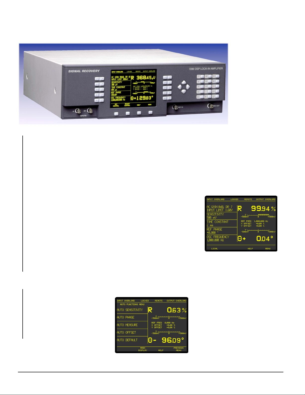
In addition to its excellent technical specifications, it is also very easy to use. The front
panel is dominated by a large electroluminescent display panel, used both to show the
instrument's outputs and for adjusting its controls via a series of menus. Controls are set
by a combination of the use of the keys surrounding the display and the numeric
keypad, while four cursor-movement keys
simplify use of the graphic display menus.
Users of the SIGNAL RECOVERY models
7260 and 7265 will find switching to the
7280 very easy, since we've designed it
with a similar menu structure. The only
significant changes are in some of the
control menus, where the better resolution
of the display allows both the controls and
the instrument outputs to be shown
simultaneously, for even faster feedback
on the effects of control adjustments.
Naturally, the instrument includes the extended operating modes like dual reference,
dual harmonic and virtual reference made popular by the 7260 and 7265, as well as the
spectral display mode used to aid reference frequency selection. It also includes GPIB
and RS232 interfaces for remote computer control and a range of auxiliary analog and
digital inputs and outputs. Compatible software is available in the form of a LabVIEW
driver supporting all instrument functions,
and the Acquire lock-in amplifier
applications software. The driver and a
free demonstration version of the
software, DemoAcquire, are available for
download from our website at
www.signalrecovery.com
In summary, if you need a lock-in capable
of working beyond the traditional audio
frequency band but still want the drift-free
performance that only digital demodulation
Auto Functions Menu
brings, then look no further - you have
found it in the SIGNAL RECOVERY Model
7280.
Main Display
CatIss7Web:0710UK www.signalrecovery.com
Page 2

Lock-in Amplifiers
Specifications
General
Dual-phase DSP lock-in amplifier operating
over a reference frequency range of 0.5 Hz to
2.0 MHz. Direct digital demodulation using a
main ADC sampling rate of 7.5 MHz.
Wide range of extended measuring modes and
auxiliary inputs and outputs. User-upgradeable
firmware.
Measurement Modes
The instrument can simultaneously show any
four of these outputs on the front panel display:
X In-phase
Y Quadrature
R Magnitude
θ Phase Angle
Noise
Harmonic nF, n ≤ 32
Dual Harmonic
Simultaneously measures the signal at
two different harmonics F1 and F2 of the
reference frequency
Dual Reference
Simultaneously measures the signal
at two different reference frequencies,
F1 and F2 where F1 is the external and F
the internal reference
Frequency Ranges for Dual Harmonic and Dual
Reference Modes:
Standard Unit F1 and F2≤ 20 kHz
With option -/99 F1 and F2 ≤ 800 kHz
With option -/98 F1 and F2 ≤ 2.0 MHz
Virtual Reference
Locks to and detects a signal without a
reference (100 Hz ≤ F ≤ 2.0 MHz)
Noise
Measures noise in a given bandwidth
centered at the reference frequency F
Spectral Display
Gives a visual indication of the spectral
power distribution of the input signal in a
user-selected frequency range lying
between 1 Hz and 2.0 MHz. Note that
although the display is calibrated in terms
of frequency, it is not calibrated for
amplitude. Hence it is only intended to
assist in choosing the optimum reference
frequency
Display
320 × 240 pixel (¼ VGA)
electroluminescent panel giving digital,
analog bar-graph and graphical indication
of measured signals. Menu system with
dynamic key function allocation. On-
screen context sensitive help
Signal Channel
Voltage Input
Modes A only, -B only or
Differential (A-B)
Full-scale Sensitivity
0.5 Hz ≤ F ≤ 250 kHz 10 nV to 1 V in a
1-2-5 sequence
250 kHz < F ≤ 2.0 MHz 100 nV to 1 V in a
1-2-5 sequence
Max. Dynamic Reserve > 100 dB
Impedance 100 MΩ // 25 pF
Maximum Safe Input 20 V pk-pk
2
Voltage Noise 5 nV/√Hz @ 1 kHz
C.M.R.R. > 100 dB @ 1 kHz
Frequency Response 0.5 Hz to 2.0 MHz
Gain Accuracy ±0.3% typ, ±0.6%
max. (full bandwidth)
Distortion -90 dB THD (60 dB
AC gain, 1 kHz)
Line Filter attenuates 50, 60,
100, 120 Hz
Grounding BNC shields can be
grounded or floated
via 1 kΩ to ground
Current Input
Mode Low Noise, Normal or
Wide Bandwidth
Full-scale Sensitivity
Low Noise 10 fA to 10 nA in a
1-2-5 sequence
Normal 10 fA to 1 µA in a
1-2-5 sequence
Wide Bandwidth
F ≤ 250 kHz 1 pA to 100 µA in a
1-2-5 sequence
F > 250 kHz 10 pA to 100 µA in a
1-2-5 sequence
Max. Dynamic Reserve > 100 dB
Frequency Response (-3 dB)
Low Noise ≥ 500 Hz
Normal ≥ 50 kHz
Wide Bandwidth ≥ 1 MHz
Impedance
Low Noise < 2.5 kΩ @ 100 Hz
Normal < 250 Ω @ 1 kHz
Wide Bandwidth < 25 Ω @ 10 kHz
Noise
Low Noise 13 fA/√Hz @ 500 Hz
Normal 130 fA/√Hz @ 1 kHz
Wide Bandwidth 1.3 pA/√Hz @ 1 kHz
Gain Accuracy ± 0.6% typ, midband
Line Filter attenuates 50, 60,
100, 120 Hz
Grounding BNC shield can be
grounded or floated
via 1 kΩ to ground
Reference Channel
TTL Input (rear panel)
Frequency Range 0.5 Hz to 2.0 MHz
Analog Input (front panel)
Impedance 1 MΩ // 30 pF
Sinusoidal Input
Level 1.0 V rms*
Frequency Range 0.5 Hz to 2.0 MHz
Squarewave Input
Level 250 mV rms*
Frequency Range 2 Hz to 2 MHz
*Note: Lower levels can be used with the
analog input at the expense of increased
phase errors
Phase Set Resolution 0.001° increments
Phase Noise at 100 ms TC, 12 dB/octave slope
Internal Reference < 0.0001° rms
External Reference < 0.01° rms @ 1 kHz
Orthogonality 90° ±0.0001°
Acquisition Time
Internal Reference instantaneous
acquisition
External Reference 2 cycles + 50 ms
Reference Frequency Meter Resolution
1 ppm or 1 mHz,
whichever is the
greater
Demodulator and Output Processing
Output Zero Stability
Digital Outputs No zero drift on all
settings
Displays No zero drift on all
settings
Analog Outputs < 5 ppm/°C
Harmonic Rejection -90 dB
Output Filters
X, Y and R outputs only
Time Constant 1 µs to 1 ms in a 1-2-5
sequence, and 4 ms
Slope (roll-off) 6 and 12 dB/octave
All outputs
Time Constant 5 ms to 100 ks in a
1-2-5 sequence
Slope 6, 12, 18 and 24 dB/
octave
Synchronous Filter Available for
F < 20 Hz
Offset Auto and Manual on X
and/or Y: ±300% fullscale
Absolute Phase Measurement Accuracy
≤ 0.01°
Oscillator
Frequency
Range 0.5 Hz to 2.0 MHz
Setting Resolution 1 mHz
Absolute Accuracy ± 50 ppm
Distortion (THD) -80 dB @ 1 kHz and
100 mV rms
Amplitude (rms)
Range 1 mV to 1 V
Setting Resolution 1 mV
Accuracy ±0.2%
Stability 50 ppm/°C
Output Impedance 50 Ω
Sweep
Amplitude Sweep
Output Range 0.000 to 1.000 V rms
Law Linear
Step Rate 20 Hz maximum
(50 ms/step)
Frequency Sweep
Output Range 0.5 Hz to 2.0 MHz
Law Linear or Logarithmic
Step Rate 20 Hz maximum
(50 ms/step)
Auxiliary Inputs
ADC 1, 2, 3 and 4
Maximum Input ±10 V
Resolution 1 mV
Accuracy ±20 mV
Input Impedance 1 MΩ // 30 pF
Sample Rate
ADC 1 only 40 kHz max.
ADC 1 and 2 17.8 kHz max.
Trigger Mode Internal, External or
burst
Trigger Input TTL compatible
www.signalrecovery.com CatIss7Web:0710UK
Page 3

Lock-in Amplifiers
Model 7280 Specifications
Outputs
Main Analog (CH1 and CH2) Outputs
Function X, Y, R, θ, Noise,
Ratio, Log Ratio and
User Equations 1 & 2.
Amplitude ±2.5 V full-scale;
linear to ±300% fullscale
Impedance 1 kΩ
Update Rate:
X, Y or R @ TC ≤4 ms 7.5 MHz
All outputs @ TC ≥5 ms 1 kHz
Signal Monitor
Amplitude ±1 V FS
Impedance 1 kΩ
Auxiliary D/A Output 1 and 2
Maximum Output ±10 V
Resolution 1 mV
Accuracy ±10 mV
Output Impedance 1 kΩ
8-bit Digital Port
0 to 8 lines can be configured as inputs,
with the remainder being outputs. Each
output line can be set high or low and
each input line read to allow interaction
with external equipment. Extra line acts
as trigger input
Reference Output
Waveform 0 to 3 V rectangular
wave
Impedance TTL-compatible
Power - Low Voltage ±15 V at 100 mA rear
panel 5-pin 180° DIN
connector for
powering
SIGNAL RECOVERY
preamplifiers
Data Storage Buffer
Size 32k × 16-bit data
points, may be
organized as 1×32k,
2×16k, 3×10.6k, 4×8k,
etc.
Max Storage Rate
From LIA up to 1000 16-bit
values per second
From ADC1 up to 40,000 16-bit
values per second
User Settings
Up to 8 complete instrument settings
can be saved or recalled at will from
non-volatile memory
Interfaces
RS232 and GPIB (IEEE-488). A second
RS232 port is provided to allow “daisychain” connection and control of up to 16
units from a single RS232 computer port
General
Power Requirements
Voltage 110/120/220/240 VAC
Frequency 50/60 Hz
Power 200 VA max
Dimensions
Width 17¼" (435 mm)
Depth 19" (485 mm)
Height
With feet 6" (150 mm)
Without feet 5¼" (130mm)
Weight 25.4 lb (11.5 kg)
SIGNAL RECOVERY Acquire
Software (see page 56)
Users who do not wish to write their own
control code but who still want to record
the instrument’s outputs to a computer file
will find the SIGNAL RECOVERY Acquire
Lock-in Amplifier Applications Software,
available at a small extra cost, useful. This
32-bit package, suitable for Windows XP/
Vista, extends the capabilities of the
instrument by, for example, adding the
ability to record swept frequency
measurements. It also supports the
internal curve buffer, allowing acquisition
rates of up to 1000 points per second
independent of the computer's processor
speed.
Model 7280 Rear Panel
LabVIEW Driver Software
A LabVIEW driver for the instrument is
available from the
www.signalrecovery.com website,
offering example VIs for all its controls and
outputs, as well as the usual Getting
Started and Utility VIs. It also includes
example soft-front panels built using these
VIs, demonstrating how you can
incorporate them in more complex
LabVIEW programs.
Ordering Information
Each model 7280 is supplied complete with a comprehensive instruction manual. Users
may download the instrument's LabVIEW driver software and a free demonstration
copy, DemoAcquire, of the SIGNAL RECOVERY lock-in amplifier applications software
package, from the www.signalrecovery.com website.
Optional Accessories
Model 7280/99 Extended frequency range (800 kHz) for Dual Reference and
Dual Harmonic Modes
Model 7280/98 Extended frequency range (2.0 MHz) for Dual Reference and
Dual Harmonic Modes
Acquire™ 32-bit lock-in amplifier applications software for use with
Windows XP/Vista operating systems
Model K02004 Rack mount to mount one model 7280 in a 19" rack
CatIss7Web:0710UK www.signalrecovery.com
Page 4

Lock-in Amplifiers
Why should you choose SIGNAL RECOVERY products?
Models 7280 and 7280BFP Wide Bandwidth DSP Lock-in Amplifiers
SIGNAL RECOVERY Product Features Benefit to you
They are the only commercially available 2 MHz genuine Allows use in systems requiring short output time constants
DSP lock-in amplifiers without problems caused by an insufficient number of samples
per signal cycle
Analog outputs updated at 7.5 MHz for use Ideal for scanned probe microscopy feedback control loops
with time constants down to 1 µs
Spectral Display (Model 7280 only) See in the frequency domain where interfering signals are and
choose a quiet region for your reference frequency
Dual Reference Measure two signals at two different frequencies simultaneously,
without the expense involved in buying two instruments
Dual Harmonic Measure two signals at two different harmonics simultaneously,
without the expense involved in buying two instruments
Curve Buffer Graphical Display Strip chart mode display is invaluable for monitoring during
manual adjustment of experiments
Virtual Reference Recover signals even without a reference
Large high resolution electroluminescent display Excellent viewing angle for good visibility even across a
(Model 7280 only) crowded laboratory
Easy to set controls with keypad and Enter the exact setting you need without having to fiddle with a
cursor movement keys (Model 7280 only) sensitive rotary knob. Move the cursors on the graphical display
with ease
User upgradeable firmware Benefit from future firmware upgrades without having to send the
instrument to a service facility
2-input multiplexing using A and -B inputs Measure two signals sequentially under computer control using
- even under computer control the same lock-in without having to switch connections
8 User Settings Memory (Model 7280 only) Several users can share an instrument but keep their own
personalized settings
Internal Oscillator can be used independently Set OSC OUT to a different frequency to the reference e.g. Use
of rest of instrument it to control a SIGNAL RECOVERY chopper at f and then
connect the lock-in's reference input to the chopper's f/10 SYNC
output
Auxiliary Digital Input and Output port Eliminate the need for separate digital I/O cards when building
complex computer controlled experiments
Excellent LabVIEW driver Saves programming time
Compatible with Acquire software Eliminates the need to develop programs
Compatible with SRInstComms Control the instrument from any ActiveX enabled programming
language, such as Visual Basic, VBA (Excel, Word, Access)
and VBScript (Internet Explorer)
CatIss7Web:0710UK www.signalrecovery.com
 Loading...