

Page 1
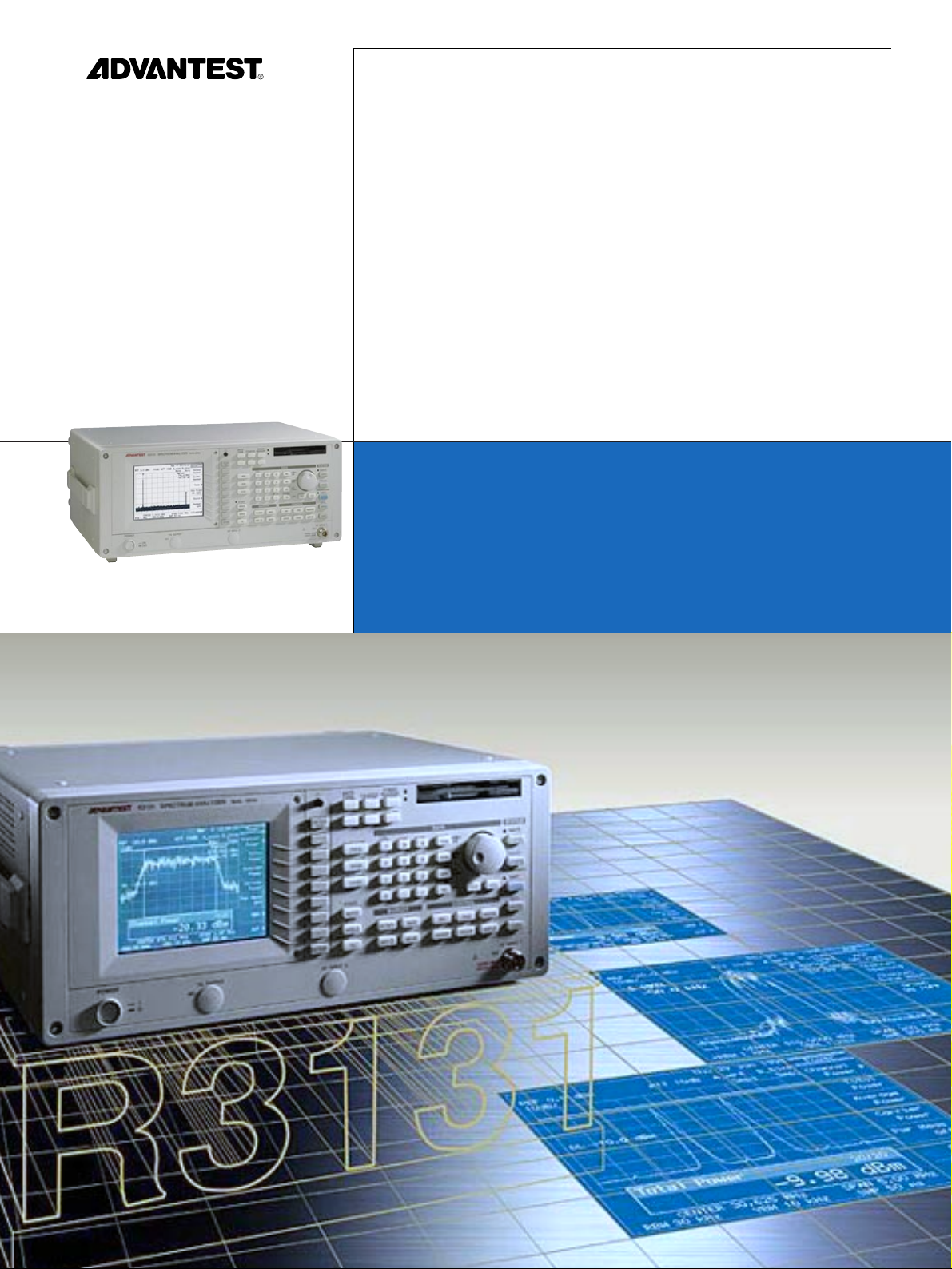
R3131
R3131
Spectrum Analyzer
A personal spectrum analyzer utilized
in diverse applications
Page 2
The R3131 is an easy-to-use
personal spectrum analyzer which
combines high accuracy
necessary for digital radio
measurement with
excellent operability
and usability.
The R3131 can be used
in diverse fields,
for a multitude of
applications.
2
R3131-2E Apr.´98
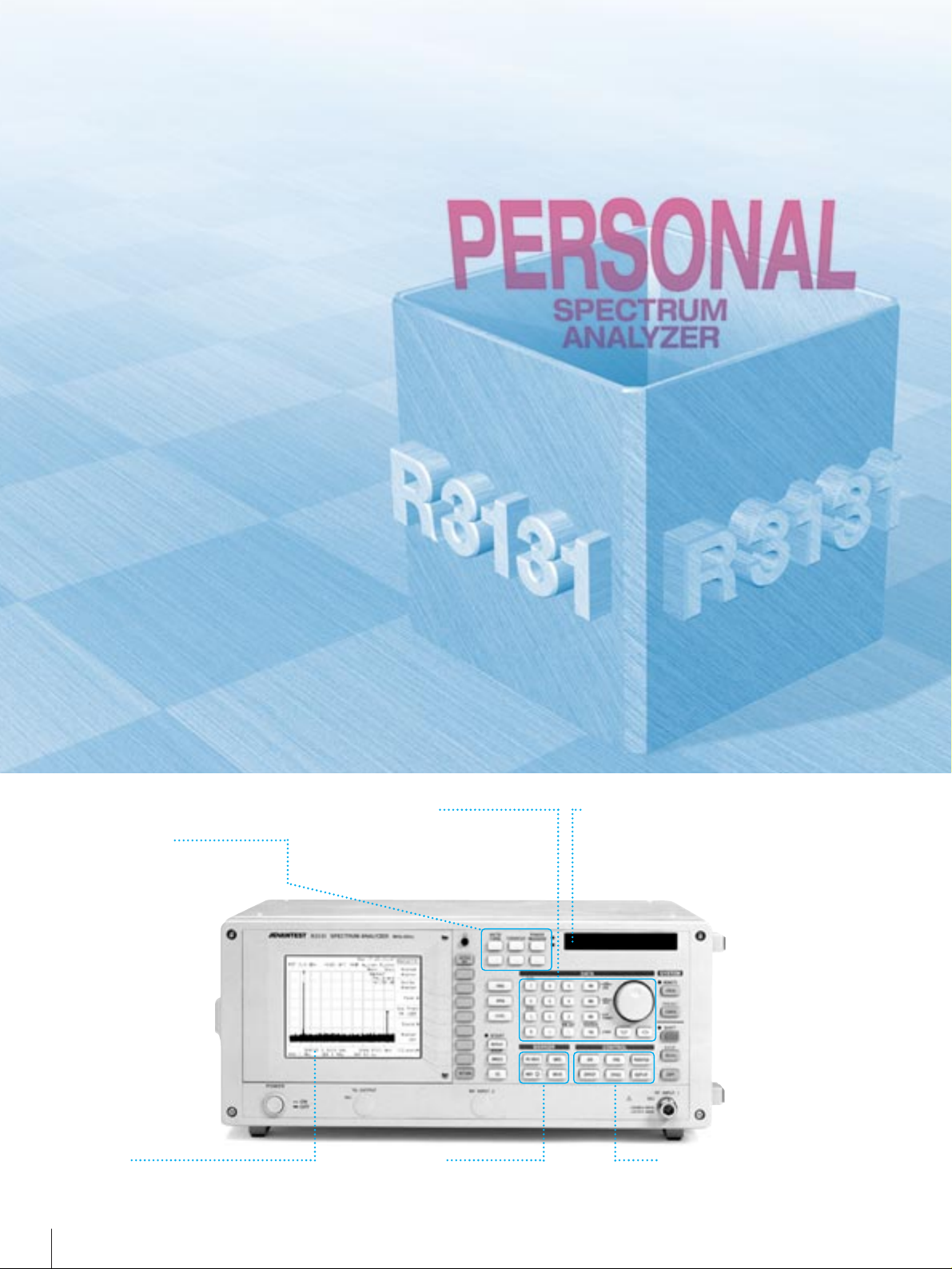
Common Keys
Auto Tune, counter and power
measurements made simple by
these keys.
Front Panel Layout
Data Entry Keys
The data entry keys arranged together
with the FREQ, SPAN, and LEVEL basic
functions improves operability.
Marker Keys
Various marker functions like delta
marker and peak search function are
available.
Control Keys
For setting bandwidth, sweep and
various parameters, R3131 meets to
all the measurements.
Floppy Disk Drive
Measurement parameters and results can be
recorded on a 3.5-inch floppy disk.Because the bit
map and text formats are compatible,the recorded
data can easily be transferred to a PC.
5.7-inch
B/W STN Display
Page 3
3
R3131-5E Oct.´98
Features
■ Built-in high accuracy OBW, ACP, and Power measurement functions
which can be applied to digital radio measurement
●Frequency stabilization
●Improved SPAN accuracy
●Improved level accuracy
■ Improved ease of use through Auto TUNE function
■ Total level accuracy guaranteed by Auto CAL function
■ Standard interfaces: GPIB, RS232C, Centronics, and FD drive
■ Large character display allows results to be seen
■ Substantial EMC measurement function
■ Improved system operation speed
■ Operation key arrangement for ease of use
■ Compact and light weight (12kg) with a space-saving design
■ High performance realized within an economical platform
■ Tracking generator option (OPT.74)
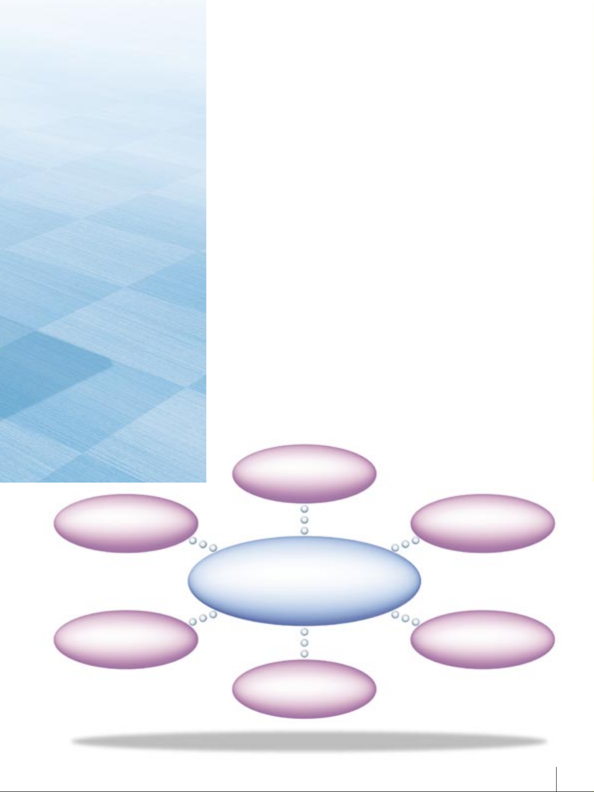
R3131
Mobile
Communications
accommodating diverse
applications
R3131
EMCParts
Installation/
Maintenance
Development/
Production lines
CATV
PERSONAL SPECTRUM ANALYZER
Page 4
Independent operation keys improve operability
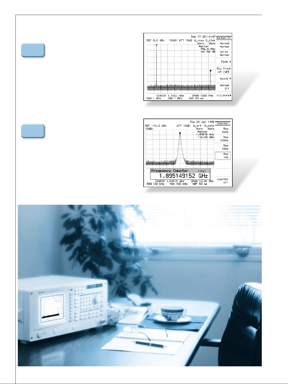
AUTO TUNE
Searches for the signal with the maximum
level within the 3 GHz band and sets the
center frequency automatically. Then,
reproduces the setting which existed
immediately before execution of AUTO
TUNE, allowing observation under the same
measurement conditions.
COUNTER
Performs frequency measurement with the
built-in frequency counter simply by moving
the marker to the signal. You can select a
measurement resolution from 1Hz up to
1kHz. The measurement results are displayed
with enlarged characters, for easy viewing.
4
R3131-2E Apr.´98
AUTO
TUNE
COUNTER
Page 5
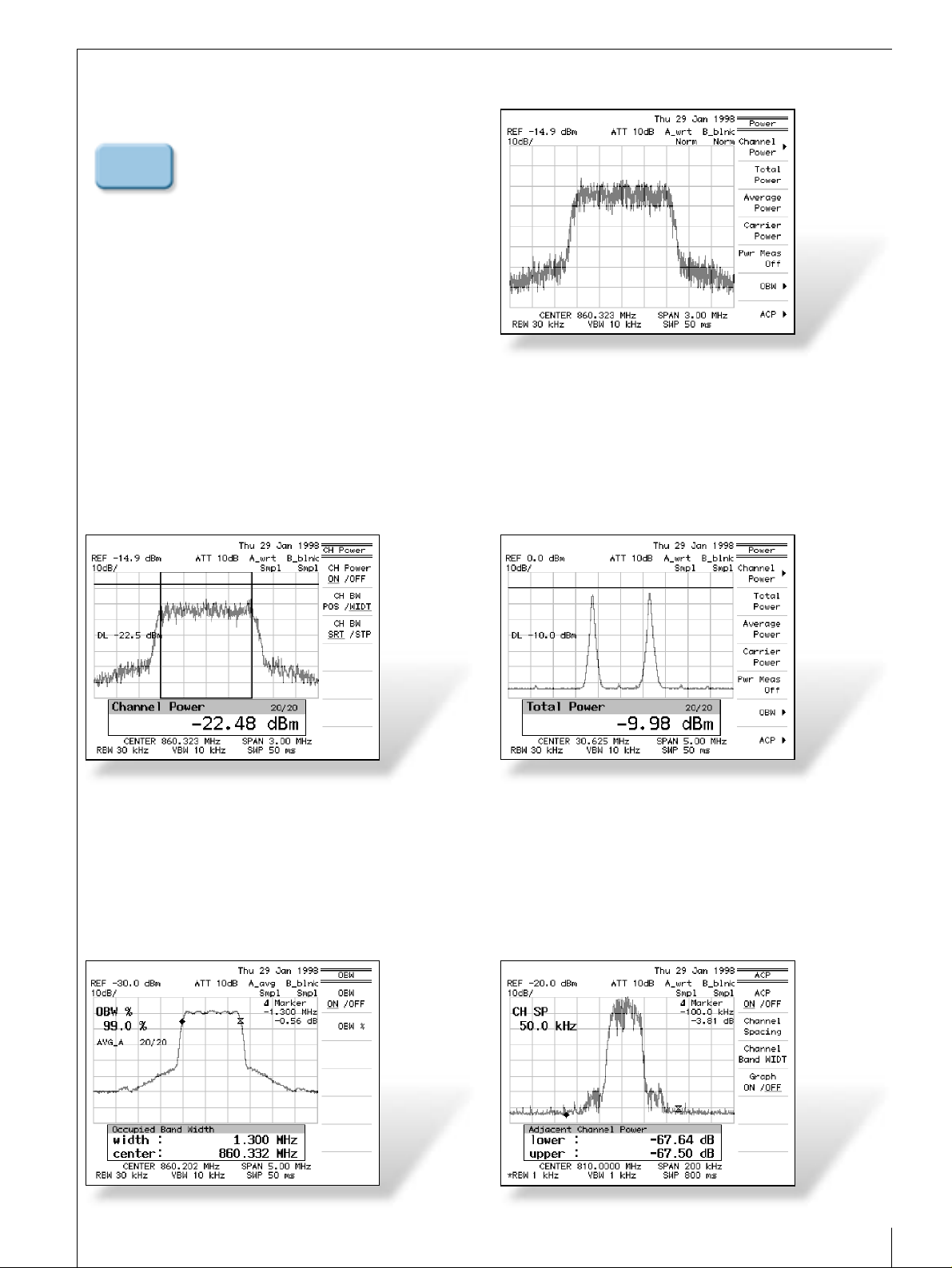
POWER MEASURE
The R3131 can measure the power within the
specified band of frequency diffuse signals and
the total power of multi-carrier signals. It can
also be used to measure the occupied
frequency bandwidth (OBW) and adjacent
channel leakage power (ACP) which are
essential to transmission characteristics testing
for radio equipment.
Channel Power
The R3131 allows you to measure the total power within the
window and display it as the channel power simply by setting
the measurement window to the specified occupied bandwidth.
Total Power
Obtains the total power from the spectrum displayed on the
screen. This function is useful for total power measurement of
multi-carrier signals.
OBW
Measures the frequency band which contains 99% of the total
power of the spectrum displayed on the screen. In addition,
the % value of OBW can be set to any desired value.
ACP
The measurement results can be displayed in graphical form,
including the upper and lower point data offset from the carrier
and the leakage power values at all the displayed frequency points.
5
R3131-2E Apr.´98
POWER
MEASURE
PERSONAL SPECTRUM ANALYZER
Page 6

SAVE/RECALL
The R3131 allows you to store and recall measured waveform
data and measurement conditions. The R3131 unit offers up
to 10 dedicated files for storage. In addition, the built-in
standard floppy disk drive allows, you to store them on MSDOS formatted floppy disks.
PASS/FAIL
Sets the limited judgment value for the level axis using a
window. If the marker falls within the window, the PASS
judgment results; otherwise, the FAIL judgment results. Since
the limit value is set as an absolute value, you can make
measurement with the same judgment value with different
REF levels. In addition, by setting the limit window for the
frequency axis, the portion where the X and Y axes overlap is
judged as the PASS region.
GATED SWEEP
Bursted signals could not directly be observed with former
spectrum analyzers. The R3131 allows spectrum analysis of the
burst signal by supplying a trigger signal synchronizing with
the burst transmission.
6
R3131-2E Apr.´98
GATED SWEEP OFF
GATED SWEEP ON
Page 7
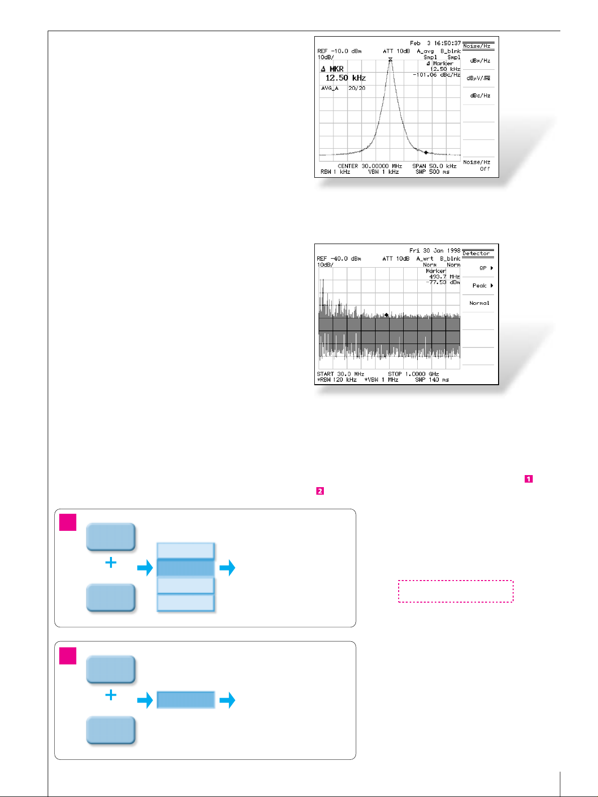
EMC
This function measures electromagnetic interference generated
by various electronic equipment. This function incorporates
the 9 kHz and 120 kHz RBW and QP detector conforming to
the CISPR Pub.16-1 standard. In addition, using the AM/FM
demodulation signal fed from the PHONE jack on the rear
panel, you can identify broadcasting radio waves which act as
external noise. Prior to measurement of noise emission on the
approved site, this function is very useful for preparatory
evaluation and solution.
Various antenna correction factors provided by Advantest are
built-in the R3131. Simply by selecting the Model name of the
antenna, the level indication of the R3131 is calibrated to an
absolute value, allowing you to read the value directly in unit
of dBµ/m. When you use an antenna from other
manufacturers, you can reflect its antenna correction factor in
the level indication of the R3131 by performing steps and
below.
Diverse measurement functions
The MEAS key incorporates the XdB Down measurement
function which is useful for noise measurement, AM
modulation measurement, 2-signal 3rd-order distortion
measurement, and filter cut-off frequency measurement. In
noise measurement, bandwidth conversion can easily be made
and the PBW calibration function for improvement of
measurement accuracy is effective. The PBW calibration
function is a new calibration function which performs
correction, in power measurement, based on conversion of the
R3131 resolution bandwidth filter to an ideal filter, thereby
allowing measurement with higher accuracy.
Antenna and Level Correction Functions (EDIT of Corr.table is not performed by the R3131 unit.)
SHIFT
RECALL
SAVE
Save
Save Item
Protect
Delete
1.Set Antenna Correction to ON and SAVE the file.
2.OPEN the file from the floppy disk using Excel
on the PC.
3.Enter the frequency and correction level in
the [ANT CORR] area and then overwrite it
on the floppy disk.
4.Load the floppy disk in the R3131 and then
RECALL the file.The Correction table is created.
Setup ON/OFF
Trace ON/OFF
Antenna
Correction
ON/OFF
MAX. 50 Points
1
2
Set Correction to ON. The corrected data is reflected
on the screen data.
SHIFT
1
EMC
Field
Correction ON/OFF
7
R3131-2E Apr.´98
Page 8

Improved system throughput
The throughput of production and adjustment lines is largely
affected by the measurement time of measuring instruments
and data transmission time. With newly developed internal
processing technology, the R3131 has shortened the time
necessary for GPIB control and data transmission by half or
more in comparison with former products. In addition, by
reducing the settling time of the local oscillator, the waveform
update rate in unit time has been doubled.
(In either case, comparison is made under the same conditions.)
Use of Data Save/Recall of the R3131
8
R3131-5E Oct.´98
Series of center frequency, sweep,
marker, and data load operations
Former products
from Advantest
Former products
from Advantest
Former products
from Advantest
Former products
from Advantest
R3131
About
2.2 seconds
About
1.2 seconds
About
1.6 seconds
About
0.7 seconds
About
0.7 seconds
About
0.3 seconds
About
5 times/
second
About
10 times/second
R3131 R3131 R3131
Trace data output
Actual measurement Trace data update
ASCII MODE BIN MODE
(with a sweep time of 50ms)
( )
Printer
R3131
Floppy
PC
Easy data management
on the PC
(.txt, .bmp)
PERSONAL SPECTRUM ANALYZER
5
Print-Out
2
Open in Excel
format
3
Data editing
1
Save in txt
format
4
Data Recall
5
Print-Out
Page 9

Short cable
Object cable
9
R3131-5E Oct.´98
OPTION
The tracking generator (OPT.74) is a monoblock option
which is integrated in R3131. It can generate constant level
signal synchronized with sweep frequency in the frequency
range up to 3 GHz and therefore can easily measure the
frequency characteristic of object device. Besides, with the
normalize function which cancels the frequency characteristic
of measuring system, highly accurate measurement is possible.
Because the output level can be set in a wide range (from 0 to
-59.9 dBm, in 0.1 dB steps), it can be used to measure filter
pass characteristic, cable loss, amplifier gain, etc.
For the measurement of reflection characteristic
With the SWR bridge, the reflection characteristic of antennas
and filters can be measured.
For the measurement of cable loss
With the short cable, the high-frequency loss characteristic of
cable can be measured from the differential when the object
cable is connected.
Tracking generator option (OPT.74)
DUT
SWR
bridge
ZRB2
Open or
short terminator
Page 10

10
R3131-5E Oct.´98
Specifications
Frequency
Range: 9 kHz to 3 GHz
Frequency reading accuracy: ± (Frequency reading x Frequency
reference accuracy+ Span x Span accuracy
+ 0.15 x Resolution bandwidth + 1 kHz)
Marker counter accuracy: ± (Marker frequency x Frequency
reference accuracy + 1 LSD)
(S/N ≥ 25 dB, SPAN ≤ 200 MHz)
Marker counter resolution: 1 Hz to 1 kHz
Frequency reference
source accuracy: ±2 ppm/year
±5 ppm at operating temperature range
Frequency span: zero, 50 kHz to 3 GHz
Frequency span accuracy: ≤ ±3%
Frequency stability
Residual FM: ≤ 100 Hzp-p/100 ms (zero span)
Sideband noise: ≤ 100 dBc/Hz (20 kHz offset)
Resolution 3 dB bandwidth: 1 kHz to 1 MHz 1-3 step
Bandwidth accuracy: ≤ ±20%
Selectivity: ≤ 15:1 (60 dB:3 dB)
6dB bandwidth: 9 kHz,120 kHz
Video bandwidth: 10 Hz to 1MHz 1-10 step
Amplitude
Amplitude measurement range
: +20 dBm to Average noise level
Maximum input level: +20 dBm, 50 VDC
Display range
LOG: 10 dB/div 8 div, 1,2,5 dB/div 10 div
LIN: 10%/div of reference level
Reference level range
LOG: -64 dBm to + 40 dBm
LIN: +141.1 µV to + 22.36 V
Input attenuator range: 0 to 50 dB 10 dB step
Sweep
Sweep time: 50 ms to 500 s
Sweep time accuracy: ≤ ±3%
Trigger mode: FREE RUN,VIDEO,EXT,LINE
Sweep mode: REPEAT, SINGLE
Dynamic range
Average noise level: -113 dBm +2 f (GHz) dB
(at RBW 1 kHz, VBW 10 Hz,
INPUT ATT 0 dB,
frequency ≥ 1 MHz)
1 dB gain compression: > -5 dBm (mixer input level, f ≥ 20 MHz)
Secondary harmonic distortion: ≤ -70 dB (input frequency ≥ 10 MHz,
mixer input level -30 dBm)
3rd Order Intermodualation: ≤ -70 dB (input frequency ≥ 10 MHz,
mixer input level -30 dBm, ∆f >50 kHz)
Other input spurious: ≤ -60 dB (offset ≥ 20 MHz,
mixer input level -30 dBm)
Residual response: ≤ -100 dBm
(Frequency ≥ 1 MHz, INPUT ATT = 0 dB,
input 50 Ω terminated)
Amplitude accuracy
Calibration signal: 30 MHz, -20 dBm ±0.3 dB
Frequency response: ≤ ±0.5 dB (100 kHz to 3 GHz, ATT = 10 dB)
≤ ±1 dB (100 kHz to 2 GHz)
≤ ±2 dB (9 kHz to 3 GHz)
(after calibration at 30 MHz reference)
Scale display accuracy
LOG: ≤ ±0.5 dB (0 to -20 dB) (after auto calibration)
≤ ±1.5 dB/70 dB (after auto calibration)
≤ ±1.0 dB/10 dB (after auto calibration)
≤ ±0.2 dB/1 dB (after auto calibration)
LIN: ±5% of reference level
Input attenuator
switching accuracy: ≤ ±0.3 dB (10 dB reference, 30 MHz)
Resolution bandwidth
switching accuracy: ≤ ±0.5 dB (after auto calibration)
IF gain error: ≤ ±0.5 dB (after auto calibration)
Total level accuracy: ±1.5 dB (after auto calibration,
REF = -50 to 0 dBm, ATT = 10 dB, 2 dB/div,
RBW = 300 kHz, f > 100 kHz)
Input/output
RF input
connector/impedance: N type jack/50 Ω (nominal)
VSWR: ≤ 1.5 (100 kHz to 2 GHz, INPUT ATT ≥ 10 dB)
≤ 2.0 (9 kHz to 3 GHz, INPUT ATT ≥ 10 dB)
10 MHz REF.
input: BNC jack, 50 Ω
Input range: -10 dBm to +10 dBm
Ext. trigger input: BNC jack, 10 kΩ (nominal), DC coupling
Phone output: Mini monophonic jack, 8 Ω
GPIB interface: IEEE-488 bus connector
Serial interface: D-SUB 9-pin
Printer interface: D-SUB 25-pin, ESC/P, PCL
Floppy disk drive: 3.5-inch, 1.4 Mbyte, MS-DOS format
General specifications
Operating conditions: 0°C to +50°C, 85%RH max.
(without condensation)
Storage conditions: -20°C to + 60°C
Power supply: 100/200 VAC, auto switching
100 VAC ; 100 V to 120 V, 50 Hz/60 Hz
220 VAC ; 220 V to 240 V, 50 Hz/60 Hz
Power consumption: 200 VA max. (100 VAC)
Weight: 12 kg or less
Dimensions: Approx. 424 mm (W) x 177 mm (H)
x 300 mm (D)
OPT.74 Tracking Generator
Frequency range: 100 kHz to 3.0 GHz
Output level range: 0 dBm to -59.9 dBm (0.1 dB step)
Output level accuracy: ≤ ±0.5 dB (30 MHz, -10 dBm, 20°C to 30°C)
Output level flatness: at -10 dBm,referenced to 30 MHz
≤ ±1.0 dB (100 kHz to 1.0 GHz)
≤ ±1.5 dB (100 kHz to 3.0 GHz)
Output level switching
error: at referenced to -10 dBm
≤±1.0 dB (100 kHz to1.0GHz, output level ≥ -30 dBm)
≤±2.0 dB (100 kHz to 2.6 GHz)
≤±3.0 dB (100 kHz to 3.0 GHz)
Output spurious
Harmonic: ≤ -20 dBc (output level =-10 dBm)
Non-harmonic: ≤-30 dBc(output level =-10 dBm)
Windows is a trademark of Microsoft Corporation.
Page 11

11
R3131-5E Oct.´98
Rear panel
RS-232
●
Remote ●Data Out
EXTERNAL TRIGGER
●
External trigger ●Gated Sweep
R3131 Spectrum Analyzer
(OPT.74 Tracking generator option)
10MHz
REFERENCE
INPUT
PRINTER
●
PCL
●
ESC-based
PHONE
GPIB
●
Remote ●Data Out
Applicable printer
control code
●
ESC/P
●
ESC/P Raster
●
HP PCL
Printers with the Centronics interface using
the above commands as control codes can be used.
Page 12

ADVANTEST CORPORATION
Shinjuku-NS building, 4-1
Nishi-Shinjuku 2-chome
Shinjuku-ku, Tokyo 163-0880,
Japan
Tel: +81-3-3342-7500
Fax:+81-3-5381-7661
http://www.advantest.co.jp
Advantest (Singapore) Pte. Ltd.
438A Alexandra Road,
#8-03/06 Alexandra Technopark
Singapore 119967
Tel: +65-274-3100
Fax:+65-274-4055
Tektronix Inc. (North America)
P. O. Box 500 Howard Vollum
Industrial Park Beaverton,
Oregon 97077-0001 U. S. A.
Tel:+1-800-426-2200
Fax:+1-503-627-4090
Rohde & Schwarz Engineering and
Sales GmbH (Europe)
Mühldorfstr. 15
(P. O. B. 80 14 29, D-81614
Munich) D-81671 München
Tel:+49-89-4129-3711
Fax:+49-89-4129-3723
Bulletin No.R3131-335E Oct. ´98 I
©
1998 ADVANTEST CORPORATION
Printed in Japan
 Loading...