

Page 1

PV Analyzer
™
PVA-600
The Complete
Verication Solution
That means:
• Condence in DC performance
at startup
• Smarter troubleshooting
• Faster installation and repairs
• Detailed history of
array performance
Verify System Performance
The Solmetric PV Analyzer is a complete electrical test solution
for verifying photovoltaic array performance. For each string, the
analyzer measures current and power as a function of voltage.
Measured results are compared to the performance predicted by
advanced built-in models.
Expert Tools.
Better Solar.
See all our solutions at
www.solmetric.com
PC not included
Key Features
• I-V and P-V graphs
• Wireless convenience
• Advanced predictive PV
models built-in
• Wireless irradiance and
temperature sensors
• Array-as-sensor mode
derives irradiance and cell
temperature
• Inverter voltage range
highlighted on I-V graphs
• Maximum input: 600V, 20A
Page 2

Application Setup
PVA Sensor Kit (optional accessory)
Fused Combiner Box
Wireless
Communication
Windows PC
Running
PVA Software
I-V
Measurement Unit
transmitter
Thermocouple
transmitterSensor
Irradiance
Testing one string at a time at a fused combiner box
Measurement Modes
For accurate calculations of I-V and P-V curves, the
irradiance and cell temperature must be known. The
PVA-600 obtains these values in three ways:
1. “Array-as-sensor” mode
In applications where the main objective is to demonstrate functionality and consistency among PV
strings, the PVA extracts the irradiance and cell temperature mathematically from the measured I-V data.
• Convenient. Uses the array itself as the sensors,
so external sensors are not required.
• Allows detailed comparison of the shapes of
measured and predicted I-V curves, even under
conditions of changing irradiance
and temperature.
2. Manual entry by the user
If external sensors are available, sensor values can
be manually entered. This method is suitable when
irradiance and temperature are relatively stable.
3. Measure using wireless sensors
With the PVA Sensor Kit, external sensors
transmit the data wirelessly, improving the overall
measurement accuracy under conditions of
changing irradiance and temperature. A complete
sensor kit is available as an accessory to support
this mode.
Page 3
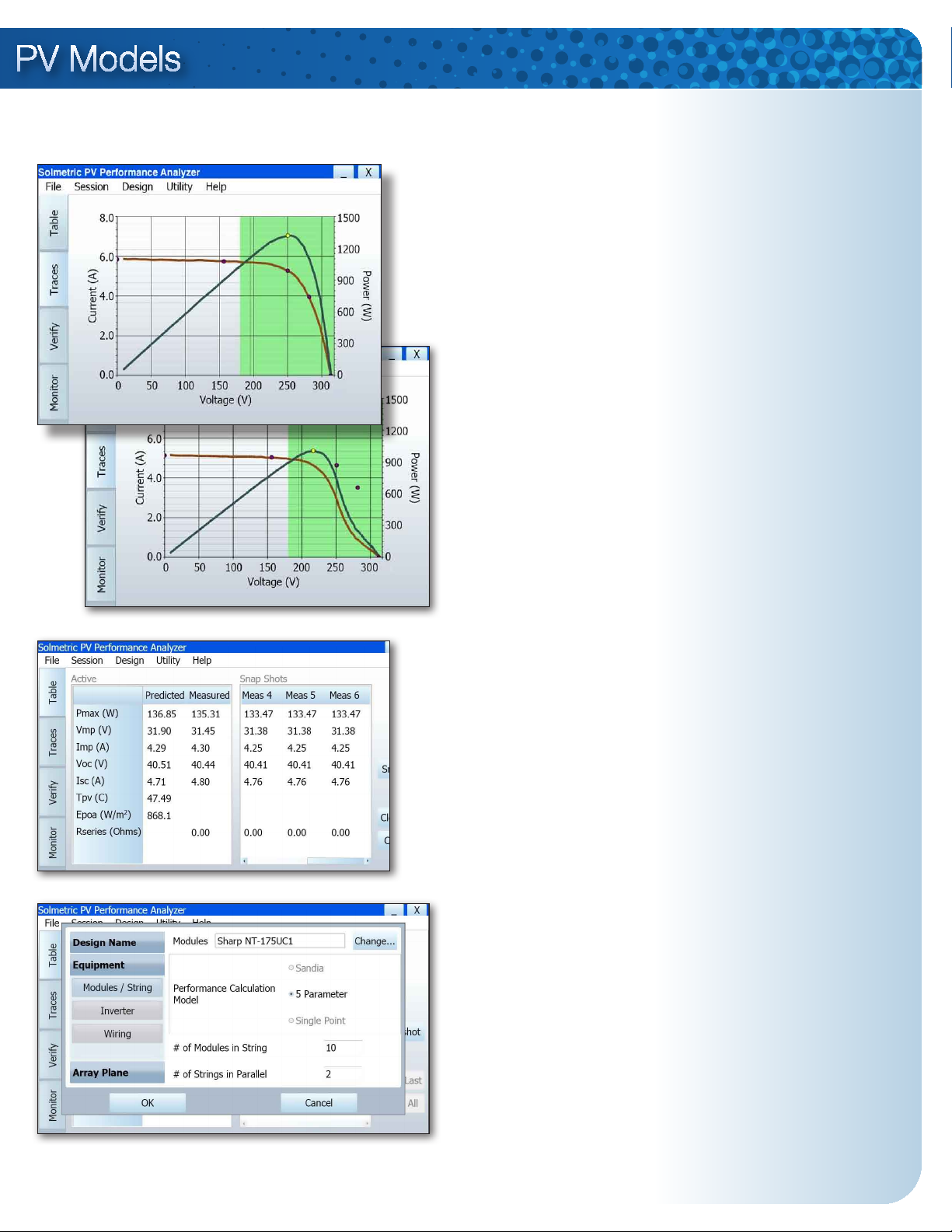
PV Analyzer User Interface
PV Model Choices
I-V and P-V curves
of a healthy PV
string. Start/Stop
inverter voltage
range is highlighted
in green.
I-V and P-V curves
of a string with bypassed cell strings.
Tabular summary
compares predicted
and measured
results. “Snapshot”
function allows
comparison of
multiple results.
Performance verication methods always require comparison of
measured results with a reference
standard. For installed PV arrays,
the standard is a PV model. The
Solmetric PV Analyzer compares
measured and modeled array performance, taking into account the
existing irradiance and temperature.
Three built-in models ensure coverage of all types of PV modules:
1. Sandia model
• The most comprehensive
PV model
• Developed by Sandia
National Laboratories
• Based on module
measurements taken in
independent laboratories
• Accounts for all performance-
related factors of a PV module
• Data for over 400 modules
is included
2. Five-parameter model
Allowing for coverage of a broader
range of PV modules, this advanced model is derived from module data sheet specications. Data
for over 1700 modules is included.
Complete
description of
the PV array
enables accurate
performance
predictions.
3. Single-point model
This model predicts the maximum
power voltage and current at the
existing irradiance and temperature. Based on data sheet values,
this model can be used with almost
any PV module with basic specications.
Page 4

Ordering Information
PV VerificationPV DesignSite Evaluation
Solmetric
SunEye
Solmetric
PV Designer
Solmetric
PV Analyzer
About Solmetric
Solmetric provides accurate,
time-saving solutions for
solar professionals.
PVA-600 PV Analyzer
Includes
• I-V Measurement Unit with soft
carrying case
• PVA Software for Windows™
• Wireless USB Interface (for
Windows laptop or UMPC)
• Connector saver jumper set (two
12-inch m-f MC-4 jumpers)
• PV cable extension set (two
5-foot m-f MC-4 jumpers)
• MC-4 to MC-3 adaptor cable
set (contact Solmetric for other
connector styles)
• Battery charger (AC adapter)
Optional Accessories
Wireless Sensor Kit:
• Irradiance sensor and
wireless transmitter
• Thermocouples (5) and
wireless transmitter
• Wireless USB Interface
(connects to Windows laptop
or UMPC)
Computer Requirements
Microsoft Windows™ 7 (64-bit or
32-bit), Windows Vista (32-bit only),
Windows XP SP3 / Processor
speed >700 MHz / RAM >500 MB
/ Hard Drive Space >100 MB /
Min. Display resolution 1024 by
600 pixels / USB ports 2 minimum
General Information
Characteristic Description
High efciency PV
modules
Measurement range
selection
Control & display unit
PC to measurement unit
interface
Wireless range
Module/Inverter data
Inverter limits
Carrying case
DC interrupt
Protection features
Dimensions
Electrical Specications
Parameter Value
PV voltage measurement range
Extra-large capacitors mean better accuracy when measuring high-efciency, back-contact PV modules.
Measurement circuitry automatically optimizes to best measure the PV module or string
User-provided Windows computer, eg. laptop or UMPC
Wireless USB adaptor (provided)
10 meters (building walls) to 75 meters (open range)
Onboard database of inverters and over 1700 modules.
Updates provided at Solmetric website.
Voltage limits and max power tracking range of user-selected
inverter are superimposed on the I-V graph as a reference
check on the system design.
Measurement unit includes a factory-installed padded soft
case, with handle, shoulder strap and cable pouch.
Measurement sweep can be paused to avoid arcing when
making/breaking connection to PV source circuits.
Automatic safeguards protect against damage from overtemperature, over-voltage, over-current, and reverse polarity.
16 in. x 8 in. x 5 in. (not including cable pouch or PV leads)
0-600 V DC
To Purchase
Online
www.solmetric.com
Call
Toll-free in US: 877-263-5026
Tel: +1-707-823-4600
Headquarters
117 Morris St. Suite 100
Sebastopol, CA 95472
www.solmetric.com
email: info@solmetric.com
Tel: +1-707-823-4600
Fax: +1-707-823-4620
PV current measurement range
Minimum Voc
Minimum Isc
I-V measurement update rate *
I-V measurement time
Measurement points per trace
Ambient operating temperature range *
Storage temperature
Battery life (continuous operation)
Charging time
* Note: Update rate should be reduced when measuring in extreme heat, or
when testing high voltage arrays.
0-20 A DC
20 V DC
1 A DC
30 – 60 sec (or on demand)
.05 – 1 sec
100
0 to +50 deg C
-20 to +60 deg C
20 hours
6 hours
 Loading...