

Page 1
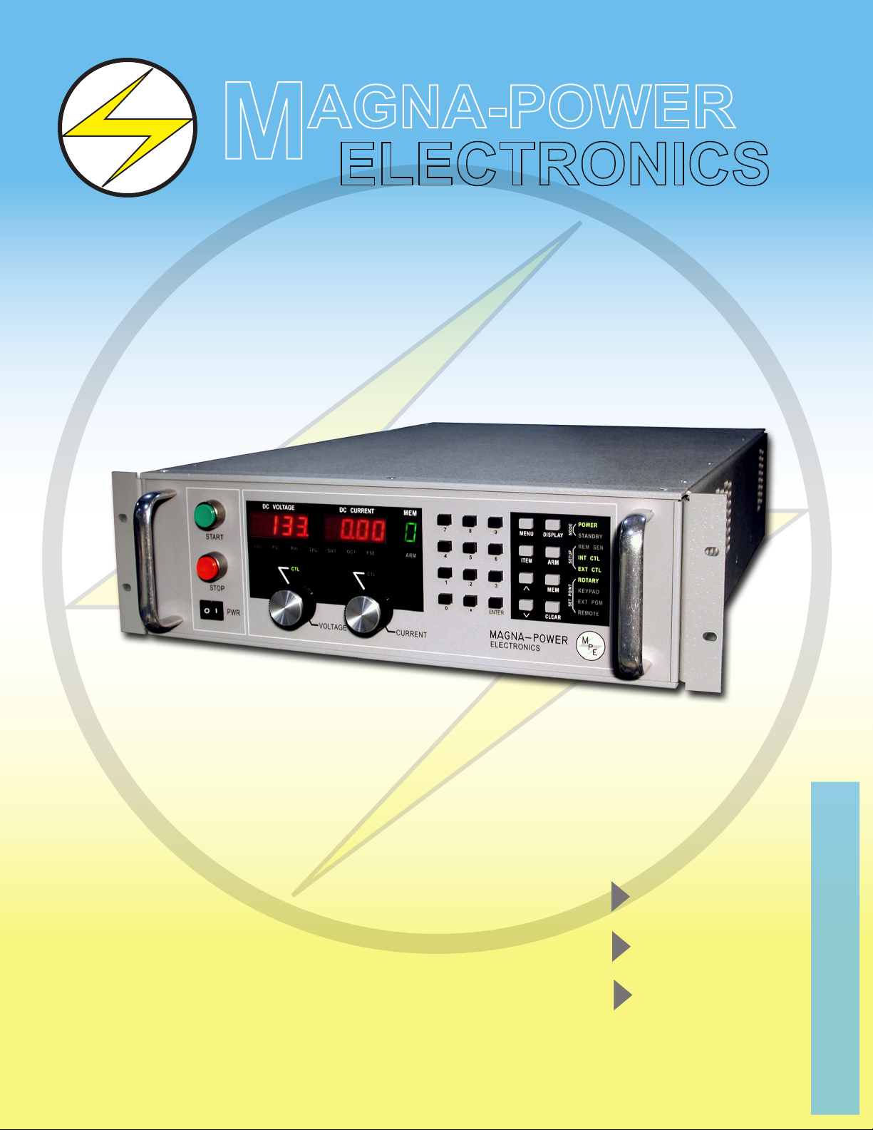
3.3 kW
M
E
P
M
AGNA-POWER
ELECTRONICS
PQ SERIES III
DC Power Supply
6.6 kW
10 kW
www.magna-power.com
Page 2
RUGGED CURRENT FED TECHNOLOGY
M
E
P
HIGH EFFICIENCY OPERATION
INNOVATIVE
Magna-Power Electronics’ PQ SERIES III combines the best of dc power
processing with multiprocessor embedded control. A combination of high and
medium frequency power processing technologies improves response, shrinks
package size, and reduces cost. PQ SERIES III power supplies are current fed and
are more tolerant to abusive loads than conventional switching power supplies.
SCALABLE POWER
PQ SERIES III power supplies oer both master/slave parallel and series
operation. This enables two or more power supplies to be placed in parallel for
increased output current or in series for increased output voltage. With master/
slave operation, power supplies operate at near equal voltage and current.
PQ SERIES III power supplies can operate as a voltage source or current
source depending on the control settings and load conditions. If the power
supply is operating as a voltage source and the load increases to a point beyond
the current command setting, the power supply automatically crosses over to
current mode control and operates as a current source at that setting.
UNPARALELLED CONTROL
PQ SERIES III power supplies can be congured through the front panel for
dierent applications. The power supply can be programmed to have its control
functions accessible from the front panel, rear connector, or through RS232 com-
munications. Sensing can be established at the output terminal of the power sup-
ply or through a rear terminal block for sensing at the load. A smart remote sense
detector checks whether or not sense leads are present eliminating the potential
of uncontrolled operation. An external interlock can be set to enable operation
only when an external connection is made. Even calibration has been simplied
with front panel access to calibration digital potentiometers.
PQ SERIES III power supplies incorporate an optically isolated feedback system.
The result is that all user interface circuitry is referenced to earth ground -- not
the negative terminal of the power supply. This enables users to connect external
circuitry without concern of ground loops or voltage breakdown.
FEATURES:
• 54 Models: 5 to 1000 Vdc, 3 to 900 Adc
• Series and parallel master/slave operation
• High dielectric withstand: 2500 Vac
• 50 Hz to 400 Hz input frequency
• All user interface circuitry referenced to
earth ground
• OVT and OCT shutdown standard
• Automatic V/I crossover
• RS232 interface with SCPI commands
• Optional IEEE-488 or Ethernet
programming
• Front panel potentiometers for stepless
rotary control
• Front panel calibration
• User friendly controls and indicators
• Remote Interface Software with self-
teaching features
• Drivers: Certied LabWindows/CVI and
LabVIEW for GPIB, Serial, and TCP/IP
communications
• Load dependent air or option water
cooling
• High power factor
• CE Mark
LOAD DEPENDENT AIR OR OPTIONAL WATER COOLING
PQ SERIES III power supplies are designed to operate at rated load 24 hours per day. Standard air cooled units are equipped
with variable speed, load dependent blowers to maintain comfortable margins for removing heat from sensitive power semicon-
ductors. Variable speed operation maximizes fan life and a minimizes external environmental hazards.
Optional water cooled models contain integrated semiconductor chillers and air to water heat exchangers to manage cooling
of heat producing components. This option allows the power supply to be sealed from the environment enabling placement in
harsh environments. These units provide long life in plating facilities, electrodionization treatment plants, shipboard, and other
corrosive environments. Water cooling also permits power supplies to be stacked in high density equipment racks where air cool-
ing is not possible or desireable.
MAGNA-POWER ELECTRONICS, INC.
39 Royal Road Ph: (908) 237-2200 Email: sales@magna-power.com
Flemington, NJ Fax: (908) 237-2201 http://www.magna-power.com
Page 3
MULTIPROCESSOR EMBEDDED CONTROL
M
E
P
ENHANCED CONTROLS AND DIAGNOSTICS
ATTENTION TO POWER QUALITY
PQ SERIES III power supplies contain circuitry to work harmoniously with other power equipment. Step-start contactors are
used to keep inrush current below full scale operating current. Filter components lower current harmonic content emanating
from the power supply and increase power factor to levels beyond 90%. Every power supply is tested at 90 to 125% nominal line
to insure satisfactory operation even under the worst line voltage conditions
DESIGNED FOR SAFETY
PQ SERIES III power supplies have extensive diagnostic functions -- all of which, when activated, take command to shut down
the system. Diagnostic functions include phase loss, excessive thermal conditions, over voltage trip, over current trip, fuse clear-
ing, and program line. Program line monitors externally applied analog set point signals to insure they are within the specied
range. Upon a diagnostic fault condition, main power is disconnected and the diagnostic condition is latched into memory.
Pressing the clear key clears the memory. All diagnostic functions can be monitored through a rear connector. Furthermore,
control functions can also be set through the rear connector to allow simultaneous control of one or more PQ SERIES III units.
PQ SERIES III supplies have three levels of over voltage/current protection: shutdown of controlling insulated gate bipolar
transistors (IGBT’s), disconnect of main power, and input fuses. After an over voltage/current trip condition, the supply must be
reset.
PQ SERIES III power supplies have push button start/stop controls. These controls are tied to a mechanical contactor which
operates with the electronic switches to break the ac mains when stop is commanded. Unlike competing products, an o means
both an electrical and mechanical break in the power circuit — not a break in an electronic switch. Safety comes rst at Magna-
Power Electronics.
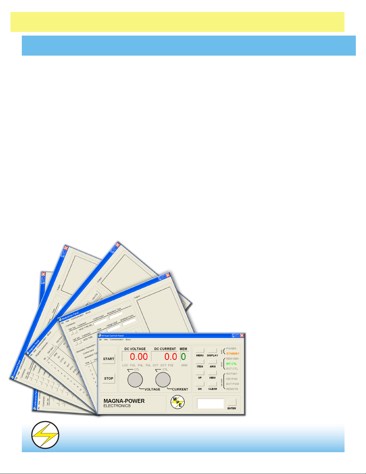
REMOTE INTERFACE SOFTWARE
INCLUDED WITH ALL MODELS
The Remote Interface Software is shipped with PQ SERIES III
power supplies. The software provides the user with a quick
method to operate a Magna-Power Electronics’ power
supply under computer control. The Remote Interface
Software has six windows: the Virtual Control Panel,
Command Panel, Register Panel, Calibration Panel,
Firmware Panel, and Modulation Panel. The Virtual
Control Panel emulates the front panel of the PQ
SERIES III power supply, the Command
panel programs and reads SCPI
commands with user friendly but-
tons, the Register Panel programs
and reads registers, the Calibra-
tion Panel enables calibration of
the digital potentiometers, the
Firmware Panel enables the pro-
gram stored internal to the power
supply to be upgraded, and the
Modulation Panel eases program-
MAGNA-POWER ELECTRONICS, INC.
39 Royal Road Ph: (908) 237-2200 Email: sales@magna-power.com
Flemington, NJ Fax: (908) 237-2201 http://www.magna-power.com
ming of modulation parameters.
Page 4

M
P
THREE CONTROL PANEL OPTIONS
M
E
P
FOR VARIOUS APPLICATIONS
FEATURES
FRONT PANEL CONTROLS
Power on/o • • •
Start/Stop • •
Rotary Voltage/Current Entry • •
Rotary OVT/OCT Entry •
Menu/Item • •
Display Settings • •
Enter/Clear • •
Keypad Voltage/Current Entry •
Keypad OVT/OCT Entry •
Arm •
INDICATORS
Voltage/Current Set Point • •
OVT/OCT Set Point • •
Voltage/Current Output • •
Internal/External Control • •
Alarms • •
Rotary/External/Remote Programming • •
Remote Sense Enabled • •
Keypad Programming •
Memory Setting •
Armed for Auto Sequence Operation •
REAR PANEL CONTROLS
Voltage/Current Set Point • •
OVT/OCT Set Point • • •
Modulation Set Point •
Voltage/Current Output • • •
Internal/External Control • • •
Alarm Outputs (9 lines) • • •
Status Outputs (6 lines) • • •
Master/Slave Connections • • •
Remote Sense Inputs • • •
RS232 Inputs • • •
Interlock Enable • • •
Arm Enable •
MODELS
PQC PQA PQD
ANALOG CONTROL
A SERIES
PQ SERIES III models utilizing the A Version front panel,
PQA, provide stepless analog control from front panel po-
tentiometers. With simple conguration changes, voltage,
current, over voltage trip, and over current trip may be pro-
grammed from the rear connector or by RS232 communica-
tions. RS232 communications is embedded in the control
circuitry allowing full computer control with SCPI com-
mands. An optional IEEE-488 to RS232 converter, Ethernet
to RS232 converter, and other communications converters
are available to echo commands over the communications
bus. PQA SERIES power supplies are well suited for indus-
trial applications requiring a minimum of control.
DIGITAL CONTROL
D SERIES
PQD SERIES models have one-hundred memory states
available to program voltage, current, over voltage trip,
over current trip, and time period. Set points can be auto
sequenced with time or external triggering. Special pro-
gramming codes allow repeating to create a power function
generator. The rst 10 memory states are displayed on the
front panel to simplify programming tasks.
PQD SERIES power supplies oer an analog input
to modulate the voltage or current setting. This feature
enables the voltage or current setting to be adjusted by a
sensor input, such as a thermistor, or by monitoring its own
voltage or current. Modulation allows the output to be
tailored for advanced process control applications, battery
charging, and source emulation.
COMPUTER CONTROL
C SERIES
PQ SERIES III models utilizing the C Version front panel,
PQC, only allow control from the rear connector or by RS232
communications. These models are intended for process
control applications where front panel controls and displays
are not required or desired.
MAGNA-POWER ELECTRONICS, INC.
39 Royal Road Ph: (908) 237-2200 Email: sales@magna-power.com
Flemington, NJ Fax: (908) 237-2201 http://www.magna-power.com
Page 5

M
E
P
DC VOLTAGE
DC CURRENT
VO LTAG E
START
STOP
PWR
MENU
3
ITEM
CLEAR
ENTER
CURRENT
DISPLAY
ARM
MEM
6
2
4 5
1
0
9
8
7
MEM
SET PO INT
SETUP
MODE
MAGNA-POWER
ELECTRONICS
I
O
16.0
600
M
E
P
4
POWER
STANDBY
REM SEN
INT CTL
EXT CTL
ROTARY
KEYPAD
EXT PGM
REMOTE
CTL
LOC OCT
OVT
THL
PHL
PGL
FSE
ARM
CTL
OVT
DC VOLTAGE
DC CURRENT
VO LTAG E
START
STOP
MODE
CONFIGURATION
MAGNA-POWER
ELECTRONICS
PWR
MENU
OCT
ITEM
V/I DIS
TRIP DIS
CLEAR
ENTER
CURRENT
ALARMS
PHASE
POWER
CTLCTL
STANDBY
INT CTL
EXT CTL
REM SEN
EXT PGM
ROTARY
REMOTE
LOCK
PGM LN
OVT
OCT
FUSE
THERM
M
E
P
PHASE
POWER
CTLCTL
STANDBY
INT CTL
EXT CTL
REM SEN
EXT PGM
ROTARY
REMOTE
LOCK
PGM LN
OVT
OCT
FUSE
THERM
16.0
600
M
E
P
I
O
I
O
M
E
P
A SERIES FRONT PANEL
Meters display voltage, current, over voltage
protection, over current protection
Switches main power on and o
MODE AND CONFIGURATION
POWER: Indicates power output
STANDBY: Indicates control power only
INT CTL: Front panel controls enabled
EXT CTL: External controls enabled
REM SEN: Indicates remote sense
EXT PGM: External voltage/current control
ROTARY: Potentiometer voltage/current control
REMOTE: RS232 control enabled
ALARMS
LOCK: Interlock
PGM LINE: Extermal input beyond limits
OVT: Shows over voltage protection has tripped
OCT: Show over current protection has tripped
FUSE: Warns that a fuse has cleared
THERM: Indicates overheating
PHASE: Indicates a problem with the input voltage
Energizes control circuits without turning
the main power on
D SERIES FRONT PANEL
ALARMS
LOC: Interlock
PGL: Warn that a program line has opened
PHL: Extermal input beyond limits
THL: Indicates over-temperature
OVT: Shows over voltage protection has tripped
Energizes control circuits without
turning the main power on
OCT: Show over current protection has tripped
FSE: Warns that a fuse has cleared
ARM: Indicates power supply is ready for or
operating in auto sequencing
Switches main
power on and o
Sets voltage and current in rotary mode
Keypad for data entry
Sets voltage and current in rotary mode
Meters display voltage,
current, over voltage protec-
tion, over current protection
FUNCTION KEYS
MENU: Select function
V/I DIS: Displays voltage and
current setting
CLEAR: Clear setting or reset fault
condition
MODE AND CONFIGURATION
POWER: Indicates power output
STANDBY: Indicates control power only
REM SEN: Indicates remote sense
INT CTL: Front panel controls enabled
FUNCTION KEYS
MENU: Select function
DISPLAY: Displays voltage and
current setting
ITEM: Select item within function
CLEAR: Clears setting or reset fault
conditions
ITEM: Select item within function
TRIP DIS: Displays OVT and OCT
setting
ENTER: Enter Setting
EXT CTL: External controls enabled
ROTARY: Potentiometer voltage/current control
KEYPAD: Keypad voltage/current control
EXT PGM: External voltage/current control
REMOTE: RS232 control enabled
ARM: arms power supply for auto
sequencing through styes
stored in memory
MEM: Sets memory
: Up
: Down
C SERIES FRONT PANEL
Energizes control circuits without turning
the main power on
Page 6

MODELS AND RATINGS
3.3 kW
MODELS
PQ5-600
PQ8-400
PQ10-300
PQ16-200
PQ20-165
PQ32-100
PQ40-82
PQ50-65
PQ80-41
PQ100-33
PQ125-26
PQ160-20
PQ200-16
PQ250-13
PQ375-8
PQ500-6
PQ600-5
PQ800-4
PQ1000-3
VOLTS
(Vdc)
0-5
0-8
0-10
0-16
0-20
0-32
0-40
0-50
0-80
0-100
0-125
0-160
0-200
0-250
0-375
0-500
0-600
0-800
0-1000
AMPS
(Adc)
0-600
0-400
0-300
0-200
0-165
0-100
0-82
0-65
0-41
0-33
0-26
0-20
0-16
0-13
0-8
0-6
0-5
0-4
0-3
MODEL ORDERING SYSTEM
SERIES
NAME
PQ
TS
MS
MT
Example: PQD32-200/208
PQ D 32 200 240
FRONT
PANEL
A: Analog
D: Digital
C: Computer
VO DC IO DC INPUT
See
Tables
See
Tables
VOLTAGE
240 SP
208
240
380
415
440
480
RIPPLE
(mVrms)
50
40
40
35
40
40
40
50
60
60
100
120
125
130
170
220
250
300
350
6.6 kW
MODELS
PQ8-800
PQ10-600
PQ16-400
PQ20-330
PQ32-200
PQ40-165
PQ50-130
PQ80-82
PQ100-66
PQ125-53
PQ160-41
PQ200-33
PQ250-26
PQ375-17
PQ500-13
PQ600-10
PQ800-8
PQ1000-6
Options:
Custom output voltage
IEEE-488 Interface
Notes:
1. Specications are subject to change without notice
2. Specify optional EMI lter to meet EMC requirements
3. For other options, consult factory
VOLTS
(Vdc)
0-8
0-10
0-16
0-20
0-32
0-40
0-50
0-80
0-100
0-125
0-160
0-200
0-250
0-375
0-500
0-600
0-800
0-1000
AMPS
(Adc)
0-800
0-600
0-400
0-330
0-200
0-165
0-130
0-82
0-66
0-53
0-41
0-33
0-26
0-17
0-13
0-10
0-8
0-6
Ethernet Interface
USB Interface
EMI Filter
RIPPLE
(mVrms)
40
40
35
40
40
40
50
60
60
100
120
125
130
170
220
250
300
350
10 kW
MODELS
PQ10-900
PQ16-600
PQ20-500
PQ32-300
PQ40-250
PQ50-200
PQ80-125
PQ100-100
PQ125-80
PQ160-62
PQ200-50
PQ250-40
PQ375-27
PQ500-20
PQ600-16
PQ800-12
PQ1000-10
VOLTS
(Vdc)
0-10
0-16
0-20
0-32
0-40
0-50
0-80
0-100
0-125
0-160
0-200
0-250
0-375
0-500
0-600
0-800
0-1000
AMPS
(Adc)
0-900
0-600
0-500
0-300
0-250
0-200
0-125
0-100
0-80
0-62
0-50
0-40
0-27
0-20
0-16
0-12
0-10
RIPPLE
(mVrms)
40
35
40
40
40
50
60
60
100
120
125
130
170
220
250
300
350
SPECIFICATIONS:
Input Voltage: • 240 Vac, 50-60 Hz, 1φ (3.3 kW only)
• 208/240 Vac, 50-400 Hz, 3φ
• 380/415 Vac, 50-400 Hz, 3φ
• 440/480 Vac, 50-400 Hz, 3φ
Line Regulation: • Voltage Mode: ± .004% of full scale
• Current Mode: ± .02% of full scale
Load Regulation: • Voltage Mode: ± .01% of full scale
• Current Mode: ± .04% of full scale
Stability: ± 0.10% for 8 hrs. after 30 min. warmup
Isolation: • Maximum input voltage to ground: ±2500 Vac
• Maximum output voltage to ground: ±1000 Vdc
• User inputs and outputs: referenced to earth ground
Power Factor: greater than 92% at maximum power.
Ambient Temperature: 0°C to 50°C
Storage Temperature: -25°C to +85°C
Temperature Coeecient: 0.04/°C of max. output current
Water Cooling:
• 25°C maximum inlet temperature
• 1.5 GPM minimum ow rate
• 80 PSI maximum pressure
• 1/4” NPT female pipe size
Eciency: ≥ 86%
Size (H” x W” x D”) and Weight:
• 3.3 kW Model: 5¼” H x 19” W x 24” D at 74 lbs
• 6.6 kW Model: 5¼” H x 19” W x 24” D at 97 lbs
• 10 kW Model: 5¼” H x 19” W x 24” D at 125 lbs
Load Transient Response: 2 ms to recover within ±1% of regulated
output with a 50% to 100% or 100% to 50% step load change
Remote sense limits:
• 3% maximum voltage drop from output terminals to load
Remote analog programming limits:
• Voltage set point: 0-2.0 Vdc
• Current set point: 0-2.0 Vdc
• Over voltage trip set point: 0 to 2.2 Vdc
• Over current trip set point: 0 to 2.2 Vdc
• Modulation: 0 to 2.0 Vdc (D Version models only)
Remote analog programming accuracy of full scale:
• Voltage set point: ±.50%
• Current set point: ±.75%
• Over voltage trip set point: ±.50%
• Over current trip set point: ±.75%
Analog monitoring accuracy of full scale:
• Output voltage: ±.50%
• Output current: ±.75%
Digital programming accuracy of full scale:
• Voltage set point: ±.50%
• Current set point: ±.75%
• Over voltage trip set point: ±.50%
• Over current trip set point: ±.75%
Digital readback accuracy of full scale:
• Output voltage: ±.50%
• Output current: ±.75%
Period programming limits:
• Minimum period: 10 msec
• Maximum period: 9997 sec or 2.77 hours
Digital control inputs and outputs limits:
• Input voltage: 0 to 5 Vdc
• Output voltages: 0 to 5 Vdc, 5 mA drive capacity per line
• 5 V supply: 25 mA
Page 7

M
E
P
SPECIAL APPLICATIONS
VOLTAGE (VDC)
CURRENT (ADC)
110
100
90
80
70
60
50
40
30
20
35
40
20
30
25
10
15
5
10
0
1,2,20
VMOD
P/O JS1
25
REF GND
24
IO2
R1
+5
3.32 K
TYPICAL
AD592
U1
+
-
VO1REM-
VO1REM+
VS-
VS+
1
2
JS2
B1
VO-
VO+
MULTIPLEXER
D1
0
10
5
15
10
25
30
20
40
35
20
30
40
506070
80
90
100
110
OUTPUT VOLTAGE (VDC)
TIME (SEC)
t
1
0
8
7
6
5
4
3
2
1
0
MEMORY
M
E
P
FOR D SERIES FRONT PANEL
POWER WAVEFORM GENERATOR
PQD SERIES power supplies can be programmed to operate as a power
waveform generator. Each memory state needs to be programmed for
the desired voltage or current for a specic time period. An example of a
power waveform generator is exemplied by the gure on the right. In this
particular example, the voltage set point is changed in 10 second intervals
while the current, over voltage trip, and over current trip are kept constant.
To make the power supply repeat the voltage ramp, a time period of 9998
is entered for step 9. The programming causes the memory state to jump
back to 0 after completing step 8.
Sawtooth output voltage
IV characteristics for a typical photovoltaic array
BATTERY CHARGER
The gure on the right illustrates a temperature compensated bat-
tery charger for applications with lead acid batteries. Diode D1, placed
between the power supply and battery, blocks current from owing from
the battery to the power supply. This eliminates any loading on the battery
when the power supply is o, but more importantly, prevents the battery
from charging the power supply’s output capacitors. With deployment of
diode D1, remote sensing should be applied across the battery terminals to
compensate for the diode drop. By setting the voltage and current to the
bulk charge voltage and maximum charge current, the power supply will
initially charge the batteries in current mode control and then automatical-
ly crossover to voltage mode control when the batteries reach the desired
set point. The power supply can be programmed for time dependent, se-
quential step operation to equalize and oat charge the batteries after bulk
charging. Equalization is generally not required for every charge cycle.
MAGNA-POWER ELECTRONICS, INC.
39 Royal Road Ph: (908) 237-2200 Email: sales@magna-power.com
Flemington, NJ Fax: (908) 237-2201 http://www.magna-power.com
PHOTOVOLTAIC CELL SIMULATOR
Modulation enables the power supply to emulate dierent sources:
such as batteries, fuel cells, photovoltaic arrays, etc. To simulate a photovol-
taic array, connect terminal 24 of JS1 to terminal 25 of JS1, set the modula-
tion control parameter to voltage control, and set the modulation type to 0.
The gure on the left illustrates the programmed piece-wise linear approxi-
mation for a typical photovoltaic array.
Battery charger with temperature compensation
Page 8

0.328
19.000
1.484
2.250 5.219
CURRENT
PWRO I
STOP
VOLTAGE
16.0
START
PGLLOC
CTL
PHL
DC VOLTAGE
600
DC CURRENT
OVTTHL OCT
CTL
FSE ARM
3
MEM
SET POINT
EXT PGM
MAGNA-POWER
0
ELECTRONICS
ENTER CLEAR
REMOTE
DISPLAY
142
5
7 8
3
6
ITEM
9 MENU
SETUP
MEM
ARM
KEYPAD
ROTARY
INT CTL
EXT CTL
MODE
STANDBY
REM SEN
POWER
POS
NEG
JS3
JS2
A
INPUT
B
GND
AIR EXHAUST
1/4-28 BOLT,
C
!
3
OUTPUT
-
+
!
2.250
JS1
OUT
2.375
1
2
24.0001.500
0.750
1.250
1.859
2.000
.390 DIA. THRU,
2 PLC'S
AIR INTAKE, BOTH SIDES
M
E
P
AIR COOLED MODELS
JS1
JS3
JS4
OPTIONAL IEEE-488
INTERFACE
JS1
JS3
JS1
JS3
JS5
JS4
OPTIONAL IEEE-488
INTERFACE
OPTIONAL ETHERNET
INTERFACE
CONNECTOR JS2
TERM PARAMETER
1
VO1REM-
2
VO1REM+
CONNECTOR JS3
TERM PARAMETER
1
NC
2
RX
3
TX
4
DTR
5
GND
6
DSR
7
RTS
8
CTS
9
NC
CONNECTOR JS1
TERM PARAMETER TERM PARAMETER
1
2
3
4
5
6
7
8
9
10
11
12
13
14
15
16
17
18
19
REF GND
REF GND
VREF EXT
TVREF EXT
VO2
REF CAL
GND
POWER
THERMAL
INTERLOCK
CUR CTL
STANDBY/ALM
ALM
EXT CTL
FUSE
RESERVE
START
CLEAR
STOP
20
21
22
23
24
25
26
27
28
29
30
31
32
33
34
35
36
37
REF GND
REF
IREF EXT
TIREF EXT
IO2
VMOD
+5
PGM LINE
STANDBY
PHASE LOSS
VOLT CTL
RESERVE
OCT
INT CTL
OVT
RESERVE
ARM
INTERLOCK SET
MAGNA-POWER ELECTRONICS, INC.
39 Royal Road Ph: (908) 237-2200 Email: sales@magna-power.com
Flemington, NJ Fax: (908) 237-2201 http://www.magna-power.com
Page 9

0.328
19.000
1.484
2.250 5.219
CURRENT
PWRO I
STOP
VOLTAGE
16.0
START
PGLLOC
CTL
PHL
DC VOLTAGE
600
DC CURRENT
OVTTHL OCT
CTL
FSE ARM
3
MEM
SET POINT
EXT PGM
MAGNA-POWER
0
ELECTRONICS
ENTER CLEAR
REMOTE
DISPLAY
142
5
7 8
3
6
ITEM
9 MENU
SETUP
MEM
ARM
KEYPAD
ROTARY
INT CTL
EXT CTL
MODE
STANDBY
REM SEN
POWER
POS
NEG
JS2
A
INPUT
B
GND
REAR PANEL
1/4-28 BOLT,
C
!
3
OUTPUT
-
+
!
2.250
OUT
2.375
1
2
JS1
JS3
WATER
OUTLET
WATER
INLET
24.0001.500
0.750
1.250
1.859
2.000
.390 DIA. THRU,
2 PLC'S
SIDE PANEL
M
E
P
WATER COOLED MODELS
JS1
JS3
JS4
OPTIONAL IEEE-488
INTERFACE
JS1
JS3
JS1
JS3
JS5
JS4
OPTIONAL IEEE-488
INTERFACE
OPTIONAL ETHERNET
INTERFACE
CONNECTOR JS2
TERM PARAMETER
1
VO1REM-
2
VO1REM+
CONNECTOR JS3
TERM PARAMETER
1
NC
2
RX
3
TX
4
DTR
5
GND
6
DSR
7
RTS
8
CTS
9
NC
CONNECTOR JS1
TERM PARAMETER TERM PARAMETER
1
2
3
4
5
6
7
8
9
10
11
12
13
14
15
16
17
18
19
REF GND
REF GND
VREF EXT
TVREF EXT
VO2
REF CAL
GND
POWER
THERMAL
INTERLOCK
CUR CTL
STANDBY/ALM
ALM
EXT CTL
FUSE
RESERVE
START
CLEAR
STOP
20
21
22
23
24
25
26
27
28
29
30
31
32
33
34
35
36
37
REF GND
REF
IREF EXT
TIREF EXT
IO2
VMOD
+5
PGM LINE
STANDBY
PHASE LOSS
VOLT CTL
RESERVE
OCT
INT CTL
OVT
RESERVE
ARM
INTERLOCK SET
MAGNA-POWER ELECTRONICS, INC.
39 Royal Road Ph: (908) 237-2200 Email: sales@magna-power.com
Flemington, NJ Fax: (908) 237-2201 http://www.magna-power.com
 Loading...