

Page 1
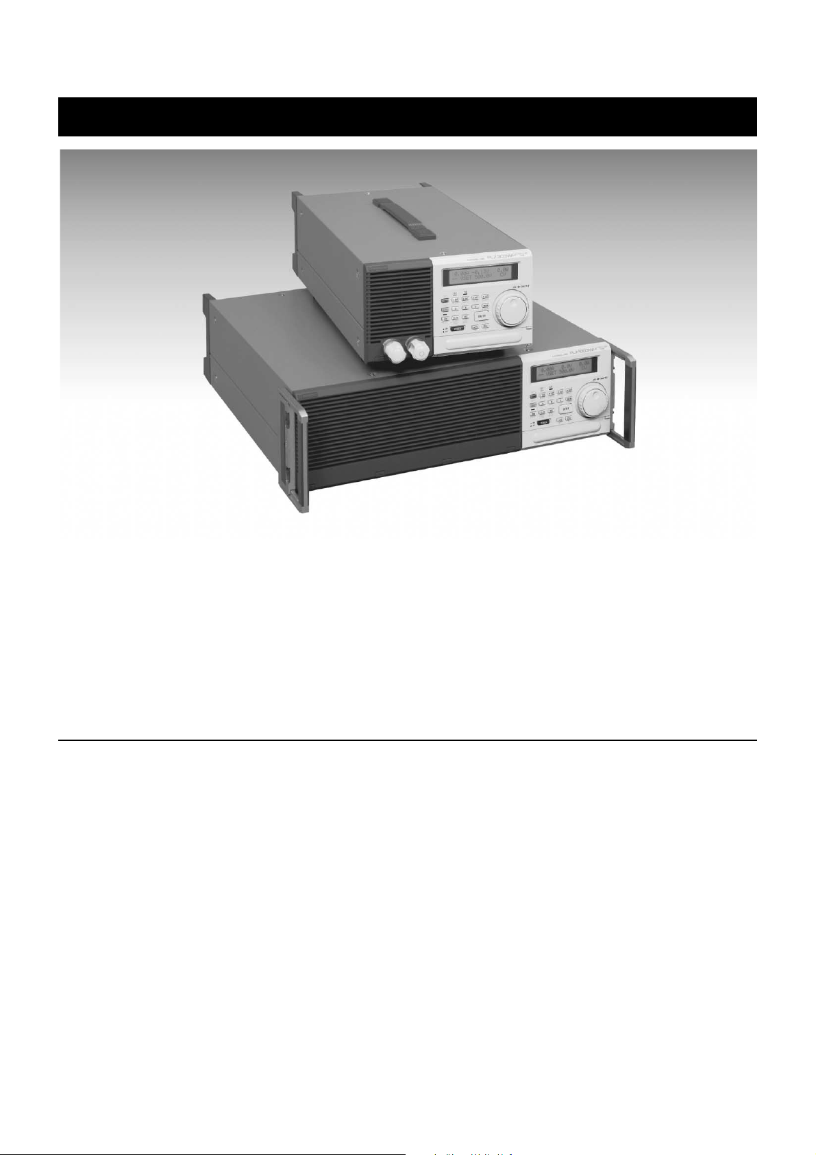
PLZ-3W/3WH series
Note: The model SMC-32 Memory Card was
discontinued. Therefore,the function related to Memory
card of this product is not equipped. <Oct. 2001>
ELECTRONIC LOAD (CC·CR·CV·CP)
Four types of power rating: 150W,300W,600W,and 1000W, a total of eight models
Ready for constant current, constant resistance, constant voltage, and constant power modes
Capable of doing actual-load simulations under sequence control
Maximum input voltage of 500V(PLZ-3WH Series)
Outline
The PLZ-3W/3WH Series are composed of system electronic
loads used either in characteristic or lifetime tests of a variety
of DC voltage sources such as switching power supplies and
primary and secondary batteries, or as burn in loads. Instruments in the PLZ-3W Series have four operation modes: “constant current”, “constant resistance”, “constant voltage”, and
“constant power”. They are also available in four different
power ratings, 150 W, 300 W, 600 W, and 1000 W, with a total
of eight models available overall. Incorporating a high-performance current control circuit, all instruments provide highly
stable, high-speed operation and offer improved operability
and multi-functionality through the use of CPU control. These
features allow them to simulate actual load tests of power supply units having large transitional changes in their output currents, such as printers and motors. In the constant power mode,
these instruments deliver performance in carrying out load tests
on alkaline and other types of batteries. Furthermore, the PLZ3WH Series accept DC input voltages of up to 500 V, making
it ready for use at high voltages. And when an optional GPIB
or RS-232C interface is employed, these instruments can be
operated by fully programmable control. In particular, take
advantage of a Kikusui-designed multi-channel bus (MCB) to
simultaneously control a maximum of 16 instruments per GPIB
address or RS-232C port. (Note: In addition to the PLZ-3W/
3WH series, this MCB will also handle PAX Series programmable power supplies and PBX Series bipolar power supplies.)
Copyright © 2001 KIKUSUI ELECTRONICS CORP. All rights reserved. http://www.kikusui.co.jp/ Page1
Page 2
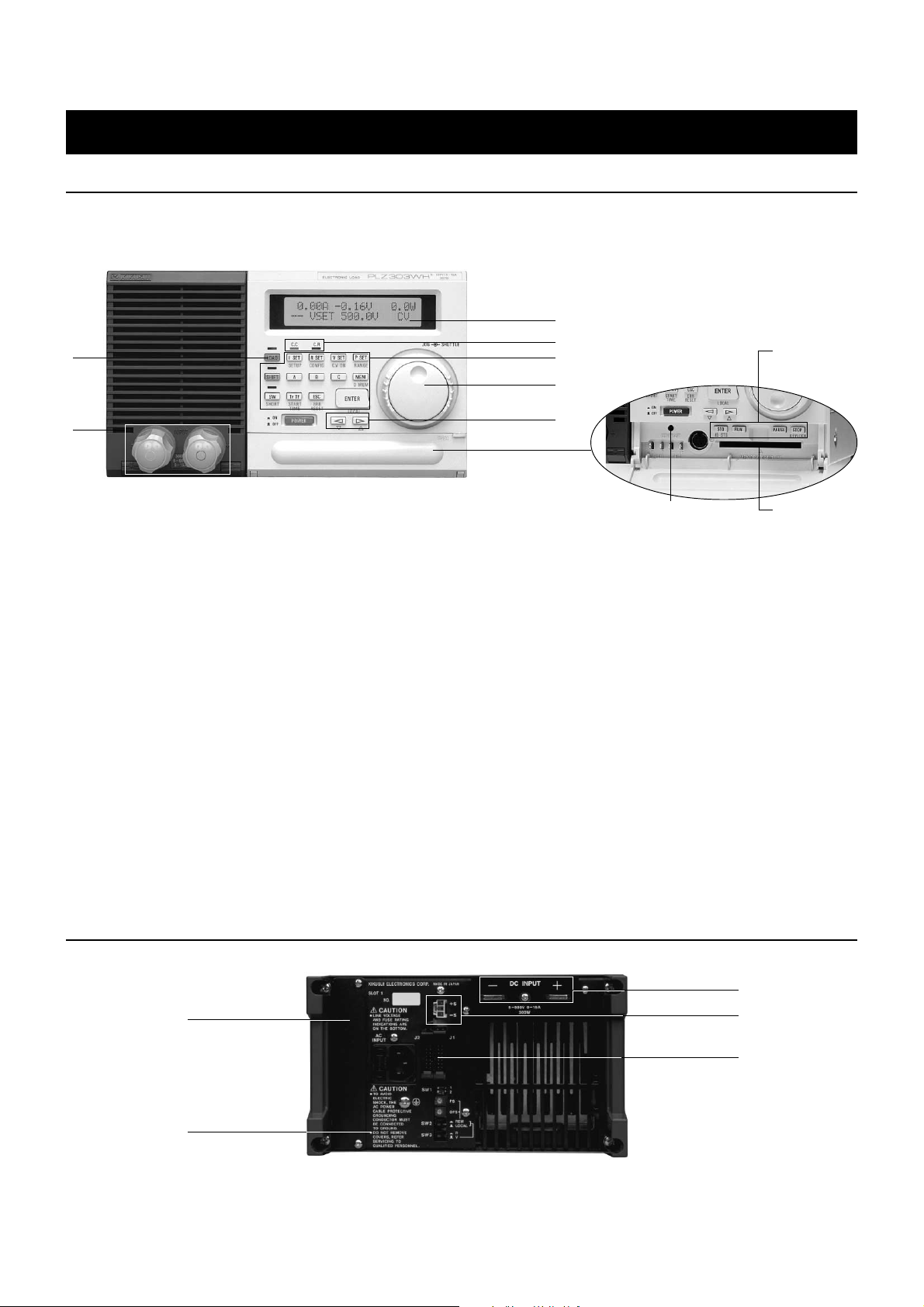
Front Panel
PLZ303WH
2
PLZ-3W/3WH series
ELECTRONIC LOAD (CC·CR·CV·CP)
3
4
5
6
8
1
1 Load terminals on the front panel
Used to connect to the device being tested. They are connected in paral
lel to the load terminals on the rear panel. (Note that PLZ603W/603WH
and PLZ1003W/1003WH have no load terminals on the front panel.)
2 LOAD key
Turns on/off current that flows through the instrument.
3 Screen (LCD with back light)
Displays the set values of current, resistance, voltage, and power; menu
items; and a variety of parameters and messages.
4 Constant current (C.C) / constant resistance (C.R) lamps
Indicate whether the instrument is in C.C or C.R mode.
5 Function keys
Used to select each mode, or to set memories or rise/fall time.
6 JOG/SHUTTLE knobs
The JOG knob is used for fine adjustments to set values or to select val
ues, and the SHUTTLE knob is used for coarse adjustments to set values.
7
10
7 Arrow keys
Used to select a menu, setting item, or a step number for program editing
in the sequence mode.
8 Sequence keys
Menu keys for sequence mode
9 Memory card slot
An optional memory card (SMC-32) is inserted here.
10 Contrast control
11 Optional board slot
An optional interface board (one of GPIB, RS-232C, and MCB) is in
serted here.
12 Remote sensing terminals
Used for remote sensing that compensates for the voltage drop caused by
resistance in load cabling.
13 External control connector
14 Load terminals
15 AC input supply voltage range selector switch (on the bottom face)
9
Rear Panel
PLZ303WH
14
11
15
Copyright © 2001 KIKUSUI ELECTRONICS CORP. All rights reserved. http://www.kikusui.co.jp/ Page2
12
13
Page 3
PLZ-3W/3WH series
ELECTRONIC LOAD (CC·CR·CV·CP)
Designed to Meet Today’s More Complex Loading Conditions
● Constant power mode useful for battery discharge tests
Loads of constant power such as DC/DC converters are being used
increasingly for batteries, and evaluation tests on such loads also require the use of constant power. Since the PLZ-3W/3WH Series have
a C.P mode, you can conduct these types of load tests (such as constant-power discharge tests) under highly realistic conditions.
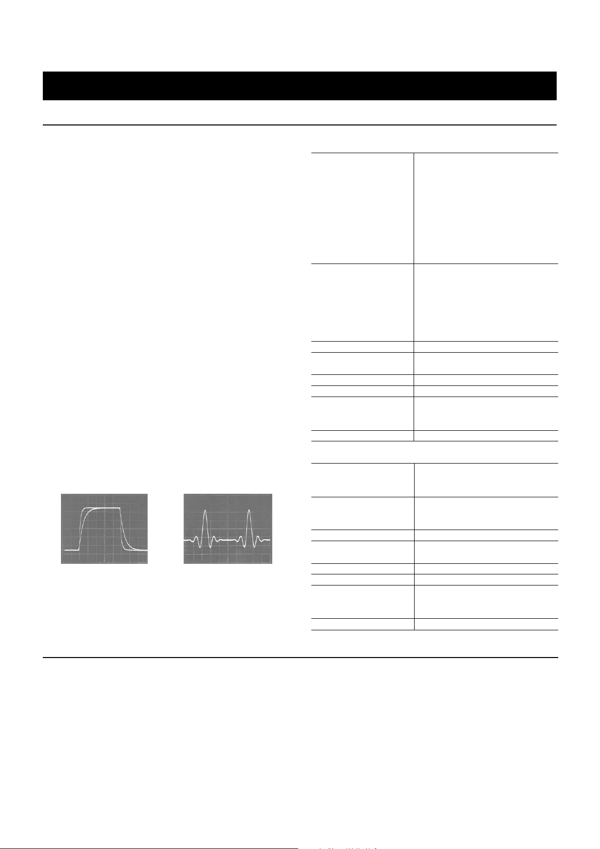
● Setting of various conditions Variable rise/fall time function
When the set current needs to change abruptly , a rise/fall time (T r/Tf)
to reach the set value can be selected using one of eight values between 50 µs and 10 ms. This allows the instruments to set up v arious
conditions for tests in order to support tests such as transitional response tests of power supplies. The instruments can also produce
accurate simulation waveforms using the sequence function. If the
device being tested has an L component, setting Tr/Tf to a slower
interval will prevent overvoltages caused by the L component. (Note:
available Tr/Tf time settings = 50 µs, 100 µs, 200 µs, 500 µs, 1 ms, 2
ms, 5 ms, and 10 ms)
● Sequence function that allows complicated current simulations
Because instruments in the PLZ-3W/3WH Series have a sequence
function that sequentially processes the data stored in each step
memory, a v ariety of current simulations may be performed. Sequence
data can be input either from the front panel or through an external
controller using an optional interface. Input data may also be stored
in an optional memory card. The sequence function offers two modes:
a fast-speed mode that enables programming of 100 µs high-speed
steps, and a normal-speed mode that allows programming of ramp
waveforms in a single step.
Rise/fall time(in C.C mode)
H: 0.2 ms/div,V: 12A/div
Rising and falling waveforms of
50 µs and 200µs
Sequence mode (in C.C mode
and fast-speed mode)
H: 5 ms/div,V: 10 A/div
● Sequence function
■ Normal Speed
Settable items I SET value (constant current),
Step execution Time can be set for each step.
time However,the range is fixed for
Pause Provided
Maximum number
of steps
Number of repetitions 1 to 9998 and ∞
Number of programs 16
Number of sequences
to be stored in a 8
memory card
Number of sequences 32 Maximum
■ Fast speed
Settable items I SET value (constant current),
Step execution Step time can be set on a
time program basis.
Pause Not provided
Maximum number
of steps
Number of repetitions 1 to 9998 and ∞
Number of programs 16
Number of sequences
to be stored in a 8
memory card
Number of sequences 32 Maximum
R SET value (constant resis
tance),
P SET value(constant power),
V SET value(constant voltage)
Trigger output
Load on/off
Setting of short-circuit function
Specification of step transition or
ramp transition
each sequence.
(1)1 to 9999 ms
(2)1 to 999.9 s
(3)1 s to 999 min and 59 s
(4)1 min to 999 hr and 59 min
256
R SET value (constant resis
tance),Tr igger output
(1)0.1 ms to 100 ms
1024
To Support Today’s More Diverse Experiments and Tests
● Setup function and backup memories
Different set values can be stored as part of a setup routine in the
built-in backup memories and in the optional memory card, where
they can be easily accessed. These backup memories can store a
maximum of four setups and the memory card, 50 setups.
● Remote sensing that compensates precisely for set values
Remote sensing will compensate for voltage drops in load lines, allowing resistance, voltage, and po wer v alues to be set precisel y. This
Copyright © 2001 KIKUSUI ELECTRONICS CORP. All rights reserved. http://www.kikusui.co.jp/ Page3
especially improves the transitional characteristics in the C.R and C.P
modes.
● Trigger signal output useful for waveform monitoring
The instruments will output trigger signals when trigger output is specified either in sequence operation or during switching operation. These
signals can then be used as synchronous signals for external instruments such as oscilloscopes, providing an easy means of waveform
observation.
Page 4
To Support Today’s More Diverse Experiments and Tests
● Three-memory function and switching function
Individual set values can be stored in three memories [A], [B], and
[C] and can be recalled freely. F or the C.C and C.R modes, the instruments have a switching function that recalls these values from the
memories in the order [A], [B], [C], [A], [B], [C], .... and executes
them repeatedly.
Switching waveform
(in C.C mode)
H: 5 ms/div, V: 10A/div
Memory A 0 A, 12 ms
Memory B 30 A, 10 ms
Memory C 59 A, 15 ms
● Soft-start function that suppresses output voltage distortion
The start-up time of the instruments can be changed in accordance
with the output-voltage rise time for the device being tested. This
allows them to conduct tests which more closely approximate realworld conditions.
(Soft-start time: Selectable from 0.1, 1, 2, 5, 10, 20, 50, and 100 ms)
Note: In case of PLZ-3WH series, selectable from 0.5ms.
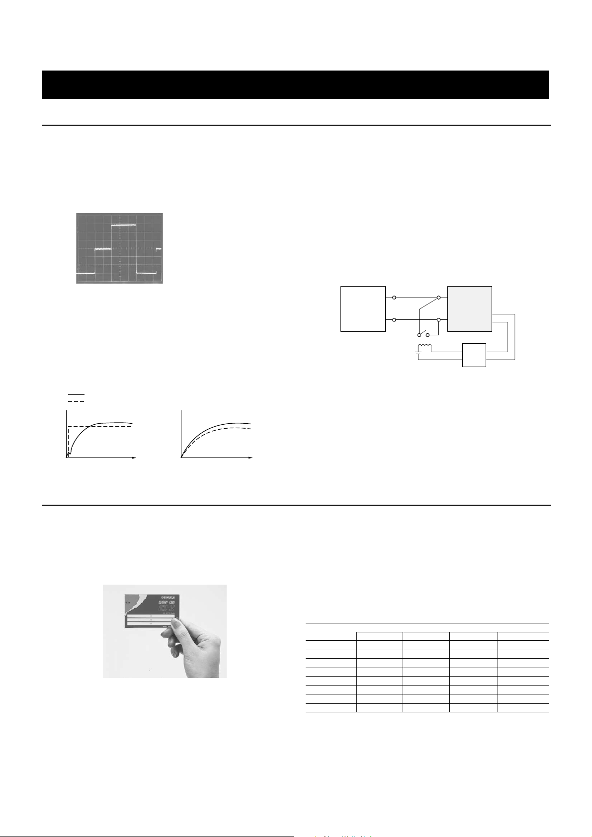
● Short-circuit function that allows instantaneous setting of the
maximum current
During operations in C.C or C.R mode, pressing the SHORT key allows you to set either the maximum current value (in C.C mode) or
minimum resistance value (in C.R mode) of the range instantaneously ,
without using the JOG or SHUTTLE key. In addition, when a largecurrent relay or other element is connected to the external control
connector as shown below, if the voltage at the load terminals falls
below approximately 1.5 V, the load terminals will be in a short-circuit state. This allows the instruments to perform effectively at currents of 1.5 V or less during current-limiting drooping characteristic
tests of DC power supplies.
PLZ-3W/3WH series
ELECTRONIC LOAD (CC·CR·CV·CP)
Device being tested
Large-current relay
+
_
+
_
PLZ-3W/3WH
Series
Buffer
DC power supply start-up time
Electronic load start-up time
Example where soft-start is not used
Time
Example where soft-start is used
Time
To Meet More Expanding Applications
● Memory card that allows significantly improved operability
Data set from the front panel or through GPIB can be saved in the
optional memory card. Using this card, other sections such as production and inspection lines can easily recall setup data and set up
current simulation data.
Memory card (SMC-32)
● Parallel operations that offer increased current and power
capacities
The PLZ-3W/3WH Series allow parallel connection of identical models in order to increase current and power capacities. In parallel operations, a single master unit can control multiple slaves, such as setting total current for all. Naturally, the total current is also displayed
on the monitors. A maximum of five instruments can be operated in
parallel.
Model
PLZ153W 300W,60A 450W,90A 600W,120A 750W,150A
PLZ303W 600W,120A 900W,180A 1200W,240A 1500W,300A
PLZ603W 1200W,240A 1800W,360A 2400W,480A 3000W,600A
PLZ1003W 2000W,400A 3000W,600A 4000W,800A 5000W,1000A
PLZ153WH 300W,15A 450W,22.5A 600W,30A 750W,37.5A
PLZ303WH
PLZ603WH
PLZ1003WH
Rated capacities in parallel operations
For 2 units For 3 units For 4 units For 5 units
600W,30A 900W,45A 1200W,60A 1500W,75A
1200W,60A 1800W,90A 2400W,120A 3000W,150A
2000W,100A 3000W,150A 4000W,200A 5000W,250A
* Please order parallel operation cable (model PC01-PLZ-3W) when connecting the
PLZ-3W/3WH Series in parallel.
Copyright © 2001 KIKUSUI ELECTRONICS CORP. All rights reserved. http://www.kikusui.co.jp/ Page4
Page 5

PLZ-3W/3WH series
RS-232C
MCB bus
16 units maximum
ELECTRONIC LOAD (CC·CR·CV·CP)
Interfaces
When an optional interface is used, the PLZ-3W/3WH Series allow
the PLZ-3W/3WH front panel to be fully controlled through an external controller. Since the e xternal contr oller can also read back DC
input voltage, DC input current, and DC input power values in addition to set values, you can use this capability to configure various
systems. Suitable interfaces include the IB11 GPIB and RS11 RS232C interfaces, both of which include the Kikusui-designed multichannel bus (MCB) feature. This allows a maximum of 16 units to
be controlled for a single address of the GPIB interface or a single
port of the RS-232C interface. (Note: The slot for an optional board
allows an IB11, RS11, or MC11S to be connected.)
Interface slot
A variety of optional interfaces
● MCB system (Example 1)
The use of the MCB allows easy configuration of various large systems when you wish to test a large number of devices together, conduct load tests of multi-output switching power supplies, or attempt
related applications.
● MCB system (Example 2 )
The MCB can also be used for the PAX Series high-speed programmable DC power supplies and PBX Series high-speed bipolar power
supplies. Thus, for example, use of a RS-232C allows a single notebook PC to configure a DC/DC converter test system using either the
PAX or PBX Series, as shown below.
Notebook PC
RS-232C
PAX•PBX
Output 1
Remote Control
By connecting a remote controller RC02-PLZ or 10-keypad RC11 to
the PLZ-3W/3WH Series, you can directly input values for current (I
SET), resistance (R SET), and power (P SET) or time settings. In
particular, the RC02-PLZ allo ws the PLZ-3W/3WH front panel to be
controlled in hand.
● Remote controller RC02-PLZ
Control items:
● Same setting features as on front panels of instruments
● Direct setting (numeric input) of I SET, R SET,V SET and P SET
values
● Direct setting (numeric input) of above SET values and time in the
memories A, B, and C
● Direct setting (numeric input) of I SET , R SET, V SET , and P SET
values and time in the sequence mode
DC input
DC/DC
converter
Output 3
PLZ-3W/3WH
Output 2
PLZ-3W/3WH
PLZ-3W/3WH
MCB
● 10-key pad RC11
Control items:
● Direct setting (numeric input) of I SET, R SET, V SET, and P SET
values
● Direct setting (numeric input) of the above SET values and time in
the memories A, B, and C
● Direct setting (numeric input) of I SET, R SET, V SET, and P SET
values and time in the sequence mode
● Load on/off
Copyright © 2001 KIKUSUI ELECTRONICS CORP. All rights reserved. http://www.kikusui.co.jp/ Page5
Page 6

Applications
● Actual-load simulations
The sequence function is used to capture real waveform data into the
memory card. This allows actual-load sim ulations to be conducted.
Capturing Data:
The load current of a motor is captured using an oscilloscope, and
the waveform data is saved in the memory card of the PLZ-3W/
3WH through the GPIB interface.
Calling the data:
As the data stored in the memory card is available even when the
GPIB interface is disconnected, you can do actual-load simulations
in test lines or without integrating a complicated system.
I
DC power supply
PLZ-3W/3WH series
ELECTRONIC LOAD (CC·CR·CV·CP)
● Automatic test system for DC current
Combining the PLZ-3W/3WH Series with a Kikusui PCR-L Series
AC power supply allows you to configure an automatic test system
for switching power supplies.
AC input side test ... PCR-L Series:
● Power line abnormality simulations
● AC line regulation tests
● Instantaneous power failure tests and others
DC roading test ... PLZ-3W/3WH Series:
● Loading simulations
● Load regulation tests
● Transitional response tests
● Current-limiting characteristic tests and others
Controller
DC power supply
Data transfer
GPIB
I
Storing waveform
Transferring to
memory card
Disconnecting the GPIB interface
Motor or other equipment
COR5500U Series digital oscilloscope
or other models
PLZ-3W/3WH
Series
Memory card
PLZ-3W/3WH Series
Memory card
Contoroller
PCR-L Series for setting
input conditions
GPIB
Switching power
AC power
supply
Digital oscilloscope Data acquisition
by the COR5500U Series or other models
PLZ-3W/3WH Series for
setting loading conditions
Copyright © 2001 KIKUSUI ELECTRONICS CORP. All rights reserved. http://www.kikusui.co.jp/ Page6
Page 7
PLZ-3W/3WH series
ELECTRONIC LOAD (CC·CR·CV·CP)
Specifications(PLZ-3WH series)
■ Operating Area
Operating voltage
(DC)*1
Current 7.5 A 15 A 30 A 50 A
Power 150 W 300 W 600 W 1000 W
Minimum operationstarting voltage*2
*1 Current can flow in a range of 1 to 5 V. However, the specifications for this instru
ment may not be met.
*2 Minimum voltage at which current starts to flow in the instrument
■ Constant Current Mode
Operating range
Range H 0 to 7.5 A 0 to 15 A 0 to 30 A 0 to 50 A
Range L 0 to 0.75 A 0 to 1.5 A 0 to 3 A 0 to 5 A
Setting accuracy
(with respect to rated
current)*1
Setting resolution
Range H 2 mA 4 mA 8 mA 13 mA
Range L 0.2 mA 0.4 mA 0.8 mA 1.3 mA
Stability
Line regulation*2 3 mA
DC input voltage regulation*3
Temperature coefficient ±100 ppm/°C of rated current (typical value)
Ripple noise*4
RMS*5 2 mA 2 mA 3 mA 5 mA
Measuring current*6 At 7.5 A At 15 A At 30 A At 50 A
Peak-to-peak 20 mA 20 mA 30 mA 50 mA
Measuring current At 7.5 A At 15 A At 30 A At 50 A
*1 In a range of 23±5°C
*2 With respect to a variation of ±10% of the center value of the input supply voltage at
the rated current of 20 V input voltage
*3 Value obtained when input voltage is varied from 5 V to 500 V at the current of rated
power/500 V
*4 At the rated current of 20 V input voltage
*5 5 Hz to 500 kHz
*6 DC to 15 MHz
■ Constant Resistance Mode
Operating range
Range H*5
Range L*5
Setting resolution
Range H*6 0.156 mS 0.3125 mS 0.625 mS 1 mS
Range L*6 0.0156 mS 0.03125 mS 0.0625 mS 0.1 mS
Setting accuracy
(current conversion)*1
Stability
DC input voltage regulation*2
Temperature ±(1000 ppm/°C + 4 mΩ/°C)
coefficient at minimum resistance value
Ripple noise*4 Complies with graph 1 (typical values)
*1 In a range of 23±5°C and at 12 V input voltage
*2 With respect to an input voltage change of 5 V to 12 V at the minimum resistance
value. For other resistance, the voltage variations will be within 6% of the maximum
conductance (S) value of the setting range with respect to variations in allinput
voltages. (with the load terminals remote sensed)
*3 α= 12 V ÷ set resistance - 12 V ÷ (set resistance + 120 mΩ)
*4 A repetitive noise of about 155 kHz may be superimposed on input current.
*5 S:siemens
*6 mS: millisiemens
Note: Conductance (S) x input voltage (V) = load current (A)
Conductance (S) = 1/resistance (Ω)
PLZ153WH PLZ303WH PLZ603WH PLZ1003WH
5 to 500 V
1 V
PLZ153WH PLZ303WH PLZ603WH PLZ1003WH
±(0.3% ±(0.3% ±(0.3% ±(0.3%
+ 7.5 mA) + 15 mA) + 30 mA) + 50 mA)
20 mA
PLZ153WH PLZ303WH PLZ603WH PLZ1003WH
1.6Ω to 20kΩ 0.8Ω to 10kΩ 0.4Ω to 5kΩ 0.24Ω to 3kΩ
0.625 to 1.25 to 2.5 to 4.17 to
5× 10⁻⁵ S 1× 10⁻⁴ S 2× 10⁻⁴ S 3.3× 10⁻⁴ S
16Ω to 200kΩ 8Ω to 100k Ω 4Ω to 50kΩ 2.4Ω to 30kΩ
0.0625 to 0.125 to 0.25 to 0.417 to
5× 10⁻⁶ S 1× 10⁻⁵ S 2×10⁻⁵ S 3.3× 10⁻⁵ S
±(1% of rated current +a)*3
6%
■ Constant Voltage Mode
Operating range (DC) 5 V to 500 V
Setting accuracy*1 ±0.1% of rated voltage
Setting resolution 125 mV
DC input current
regulation*2
Temperature coefficient ±100 ppm/°C of rated voltage (typical value)
*1 In a range of 23±5°C (with the load terminals remote sensed)
*2 With respect to an input current change of 10% to 100% of the rated current at 5 V
input voltage (with the load terminals remote sensed)
■ Constant Power Mode
Operating range 15 to 150 W 30 to 300 W 60 to 600 W 100 to 1000 W
Setting accuracy*1 ±2% of rated power
Setting resolution 0.025% of rated power
DC input voltage regulation*2
Ripple current*3 Complies with graph 2 (typical values)
Temperature coefficient ±1000 ppm/°C of rated power (typical value)
*1 In a range of 23±5°C and at 20 V input voltage (with the load terminals remote sensed)
*2 With respect to an input voltage change of 20 V to 500 V at rated power (with the load
terminals remote sensed)
*3 When the ripple noise of input voltage is 5 mV or less
■ Tr/Tf, Switching and Soft-start Operations, Remote Sensing, and Protective Features
Tr/Tf setting*1
Operation mode Constant current
Setting range 50, 100, 200, 500 µs
Setting accuracy*2 ±30% of set value, ±15 µs
Switching operation
Operation mode Constant current, constant resistance
Time setting range 1 to 5000 ms
Time setting accuracy ±5% of set value
Soft-start operation
Operation mode Constant current(C.C)
Setting range 0.5, 1, 2, 5, 10, 20, 50, 100 ms
Setting accuracy ±30% of set value, ±100 µs
Remote sensing
Sensing voltage 5 V*3
Protective features
Over current protection
(OCP) +5% of rated current.
Overheat protection Load current is cut off at a he
(OHP) at sink temperature of about 105°C.
Reverse connection
protection
Power transistor
protection
Overvoltage protection
(OVP)
*1 Within an input voltage range of 12 V to 500 V.
Rise time (Tr) and fall time (Tf) are times required to reach 10% to 90% of current
waveform.
*2 Tr/Tf setting is valid when the changes in load current fall within a range of 2% to
100% of the rated current value.
*3 2.5 V at one terminal
PLZ153WH PLZ303WH PLZ603WH PLZ1003WH
±0.01% of rated voltage
PLZ153WH PLZ303WH PLZ603WH PLZ1003WH
2% of rated power
PLZ153WH PLZ303WH PLZ603WH PLZ1003WH
1, 2, 5, 10 ms
Limit is activated at about
With diodes and fuses
With fuses
Load switch will be turned off.
Copyright © 2001 KIKUSUI ELECTRONICS CORP. All rights reserved. http://www.kikusui.co.jp/ Page7
Page 8

PLZ-3W/3WH series
ELECTRONIC LOAD (CC·CR·CV·CP)
■ External Control Connector
I/O slot One of IB11, RS11, and MC11S can be connected.
Voltage control 0 A when voltage is 0 V, and rated current when
terminals for C.C/C.R *1 10 V (in C.C mode)
Resistance control Rated current when resistance is about 0 Ω,
terminals for C.C/C.R and 0 A when about 10 kΩ (in C.C mode)
Voltage control
terminals for C.P
Load-on/off monitoring Photo coupler (open collector)
output terminals Rated voltage: 30 V
(floating output) Rated current: 5 mA
Load-on/off signal Comparator level: about 7 V
input terminal 3.3 kΩ is pulled up at 15 V.
Range selector signal
input terminals
Trigger signal output terminals (floating output)
Output resistance 10 kΩ
Output voltage 3.5 V
Pulse width Approx. 10 µs
Trigger input terminals CMOS level Pull down at 100 kΩ.
Current monitoring
terminals (output of Rated current/1 V
a sum of currents)
Short-circuit signal
output
*1 In full scale, and offset adjustable
PLZ153WH PLZ303WH PLZ603WH PLZ1003WH
Maximum resistance when voltage is 0 V,
and minimum resistance when 10 V (in C.R mode)
Minimum resistance when resistance is about 0 Ω,
and maximum resistance when about 10 kΩ (in C.R mode)
Rated power when voltage is about 10 V
CMOS level 10 kΩ is pulled up at 5 V.
Relay contact output (25 V DC, 0.5 A)
■ Others
Input power supply (AC)
Input supply voltage
range AC
Frequency 50/60 Hz AC
Power consumption (VA)
(When the GPIB
board is connected)
Rush current (A) Approx. 18 Approx. 22 Approx. 28 Approx. 32
Withstand voltage
Primary circuit to
load terminals
Primary circuit to
chassis
Load terminals to
chassis
Insulation resistance
Primary circuit to
load terminals
Primary circuit to
chassis
Load terminals to
chassis
Operating
temperature range
Operating
humidity range
Storage
temperature range
Storage humidity range 30 to 80% RH (no condensation)
Weight (kg) Approx. 8.5 Approx. 10 Approx. 16 Approx. 19.5
PLZ153WH PLZ303WH PLZ603WH PLZ1003WH
Range Center voltage
[1] 90 to110 100
[2] 108 to132 120
[3] 180 to220 200
[4] 216 to250 240
[1], [2], [3], or [4] is selectable.
Approx. 50 Approx. 50 Approx. 65 Approx. 80
(60) (60) (75) (90)
1500 V AC for 1 min
1500 V AC for 1 min
500 V DC for 1 min
1000 V DC, 30 ΜΩ or more
1000 V DC, 30 ΜΩ or more
1000 V DC, 20 ΜΩ or more
0 to 40°C
30 to 80% RH (no condensation)
-20 to 70°C
■ Indicators
Ammeter
Display digits 7.500A 15.00A 30.00A 50.00A
Accuracy*1 ±(0.25% of
Temperature coefficient
Voltmeter
Display digits 500.0V
Accuracy*1 ±(0.2% of FS + 2 digits)
Temperature coefficient
Power meter
Display digits 150.0W 300.0W 600.0W 1000W
*1 In a range of 23±5°C
PLZ153WH PLZ303WH PLZ603WH PLZ1003WH
FS + 2 digits)
±(0.25% of FS + 1 digit)
±100 ppm/°C of FS (typical value)
±100 ppm/°C of FS (typical value)
Displays the results of multiplying current value
and voltage value. ±8% of FS
■ Sub-front panel
Current monitoring
terminals
Remote control 8-pin mini-connector
connector (RC11 or RC02-PLZ is connectable.)
Trigger signal output terminals
Output resistance 10 kΩ
Output voltage 3.5 V
Pulse width Approx. 10 µs
Rated voltage
PLZ153WH PLZ303WH PLZ603WH PLZ1003WH
1 V output at rated current
Graph 1 Setting Resistance and Current Ripple
1.0
0.9
0.8
0.7
0.6
0.5
0.4
0.3
Current ripple P-P(A)
0.2
0.1
0
0.1 0.625 1 1.25 2.5 4.16 10
(10Ω) (1.6Ω) (1Ω)(0.8Ω) (0.4Ω)(0.24Ω) (0.1Ω)
0.8
Graph 2 Setting Power and Current Ripple
0.7
0.6
0.5
0.4
Current ripple P-P(A)
0.3
0.2
0.1
•
0
10 20 30 40 50 60 500
(500V)
Input voltage
5V
0
Setting resistance(
•
•
Input voltage(V)
Graph 3 Operationg Range
Rated power
Input current
Ω
)
1000W
600W
•
300W
150W
•
Rated current
(S)
Copyright © 2001 KIKUSUI ELECTRONICS CORP. All rights reserved. http://www.kikusui.co.jp/ Page8
Page 9

PLZ-3W/3WH series
ELECTRONIC LOAD (CC·CR·CV·CP)
Specifications(PLZ-3W series)
■ Operating Area
Operating
voltage (DC)
Current 30 A 60 A 120 A 200 A
Power 150 W 300 W 600 W 1000 W
Minimum operationstarting voltage*1
*1 Current can flow in a range of 0.3 to 1.5 V. However, the specifications for this
instrument may not be met.
■ Constant Current Mode
Operating range
Range H 0 to 30A 0 to 60A 0 to 120 A 0 to 200 A
Range L 0 to 3 A 0 to 6 A 0 to 12 A 0 to 20 A
Setting accuracy
(with respect to rated
current)*1
Setting resolution
Range H 8 mA 15 mA 30 mA 60 mA
Range L 0.8 mA 1.5 mA 3 mA 6 mA
Stability
Line regulation*2 3 mA
DC input voltage
regulation*3
Temperature coefficient
Ripple noise*4
RMS*5 3 mA 5 mA 10 mA 20 mA
Measuring current*6 At 30 A At 60 A At 100 A At 100 A
Peak-to-peak 30 mA 30 mA 50 mA 100 mA
Measuring current At 30 A At 60 A At 100 A At 100 A
*1 In a range of 23±5°C
*2 With respect to a variation of ±10% of the center value of input supply voltage at the
rated current of 5 V input voltage
*3 Value obtained when input voltage is varied from 1.5 V to 120 V at the current of rated
power/120 V
*4 At the rated current of 1.5 V input voltage
*5 5 Hz to 500 kHz
*6 DC to 15 MHz
■ Constant Resistance Mode
Operating range
Range H*4
Range L*4
Setting resolution
Range H*5 0.25 mS 0.5 mS 1 mS 2.5 mS
Range L*5 0.025 mS 0.05 mS 0.1 mS 0.25 mS
Setting accuracy
(current conversion)*1
Stability
DC input voltage regulation*2
Temperature coefficient
Ripple noise Complies with graph 1 (typical values)
*1 In a range of 23±5°C and at 3 V input voltage
*2 With respect to an input voltage change of 1.5 V to 3.0 V at the minimum resistance
value. For other resistance, the voltage variations will be within 6% of the maximum
conductance (S) value of the setting range with respect to variations in all input voltages. (These values were obtained with the load terminals remote sensed.)
*3 α= 3 V ÷ set resistance - 3 V ÷ (set resistance + 8 mΩ)
*4 S:siemens
*5 mS: millisiemens
Note: Conductance (S) x input voltage (V) = load current (A)
Conductance (S) = 1/resistance (Ω)
PLZ153W PLZ303W PLZ603W PLZ1003W
1.5 to 120 V
0.3 V
PLZ153W PLZ303W PLZ603W PLZ1003W
±(0.3% ±(0.3% ±(0.3% ±(0.3%
+ 30 mA) + 60 mA) + 120 mA) +200 mA)
10 mA
±100 ppm/°C of rated current (typical value)
PLZ153W PLZ303W PLZ603W PLZ1003W
0.1 to 10 Ω 0.05 to 5 Ω 0.025 to 2.5 Ω 0.015 to 1 Ω
10 to 0.1 S 20 to 0.2 S 40 to 0.4 S 66 to 1 S
1 to 100 Ω 0.5 to 50 Ω 0.25 to 25 Ω 0.15 to 10 Ω
1 to 0.01 S 2 to 0.02 S 4 to 0.04 S 6.6 to 0.1 S
±(1% of rated current + α)*3
6%
±(1000 ppm/°C + 1 mΩ/°C)
at minimum resistance value
■ Constant Voltage Mode
Operating range (DC) 1.5 V to 120 V
Setting accuracy*1 ±0.1% of rated voltage
Setting resolution 30 mV
DC input current
regulation*2
Temperature
coefficient
*1 In a range of 23±5°C (with load terminal remote sensing)
*2 With respect to a change in the input current of 10% to 100% of the rated current at 1.5
V input voltage (with load terminal remote sensing)
PLZ153W PLZ303W PLZ603W PLZ1003W
±0.01% of rated voltage
±100 ppm/°C of rated voltage (typical value)
■ Constant Power Mode
Operating range (DC) 15 to 150 W 30 to 300 W 60 to 600 W 100 to 1000 W
Setting accuracy*1 ±2% of rated power
Setting resolution 0.025% of rated power
DC input voltage
regulation*2
Ripple current*3 Complies with graph 2 (typical values)
Temperature
coefficient
*1 In a range of 23±5°C and at 5 V input voltage (with load terminal remote sensing)
*2 With respect to an input voltage change of 6 V to 120 V at rated power (with load
terminal remote sensing)
*3 When the ripple noise of input voltage is 5 mV or less
PLZ153W PLZ303W PLZ603W PLZ1003W
2% of rated power
±1000 ppm/°C of rated power (typical value)
■ Tr/Tf, Switching and Soft-start Operations, Remote Sensing, and Protective Features
Tr/Tf setting*1
Operation mode Constant current
Setting range 50, 100, 200, 500 µs
Setting accuracy*2 ±30% of set value, ±15 µs
Switching operation
Operation mode Constant current, constant resistance
Time setting range 1 to 5000 ms
Time setting accuracy ±5% of set value
Soft-start operation
Operation mode Constant current(C.C)
Setting range 0.1, 1, 2, 5, 10, 20, 50, 100 ms
Setting accuracy ±30% of set value, ±100 µs
Remote sensing
Sensing voltage 5 V*3
Protective features
Over current protection
(OCP)
Overheat protection Load current is cut off at a heat sink
(OHP) temperature of about 105°C.
Reverse connection
protection
Power transistor
protection
Overvoltage protection
(OVP)
*1 In an input voltage range of 3 V to 120 V.
Rise time (Tr) and fall time (Tf) are times required to reach 10% to 90% of current
waveform.
*2 Tr/Tf setting is valid when the range of changes in load current is 2% to 100% of the
rated current value.
*3 2.5 V at one terminal
PLZ153W PLZ303W PLZ603W PLZ1003W
1, 2, 5, 10 ms
Limit is activated at about +5% of rated current.
With diodes and fuses
With fuses
Load switch will be turned off.
Copyright © 2001 KIKUSUI ELECTRONICS CORP. All rights reserved. http://www.kikusui.co.jp/ Page9
Page 10

PLZ-3W/3WH series
ELECTRONIC LOAD (CC·CR·CV·CP)
■ Indicators
Ammeter
Display digits 30.00A 60.00A 99.99A 99.99A
Accuracy*1 ±(0.25% of FS + 1 digit) ±(0.25% of FS + 3 digits)
Temperature coefficient
Voltmeter
Display digits 99.99V 120.0V*3
Accuracy*1 ±(0.2% of FS + 1 digit)
Temperature coefficient
Power meter
Display digits 150.0W 300.0W 600W 1000W
*1 In a range of 23±5°C
*2 For 100 A or more, up to one digit below the decimal point will be indicated.
*3 For 100 V or more, up to one digit below the decimal point will be indicated.
PLZ153W PLZ303W PLZ603W PLZ1003W
120.0A*2 200.0A*2
±100 ppm/°C of FS (typical value)
±100 ppm/°C of FS (typical value)
Displays the results of multiplying
current value and voltage value.
■ Sub-front panel
Current monitoring
terminals
Remote control 8-pin mini-connector
connector (RC11 or RC02-PLZ is connectable.)
Trigger signal output terminals
Output resistance 10 kΩ
Output voltage 3.5 V
Pulse width Approx. 10 µs
PLZ153W PLZ303W PLZ603W PLZ1003W
1 V output at rated current
■ Others
Input power supply (AC)
Input supply voltage
range (AC)
Frequency 50/60 Hz AC
Power consumption (VA)
(When the GPIB board
is connected)
Rush current (A) Approx. 18 Approx. 22 Approx. 28 Approx. 32
Withstand voltage
Primary circuit to
load terminals
Primary circuit to
chassis
Insulation resistance
Primary circuit to
load terminals
Primary circuit to
chassis
Load terminals to
chassis
Operating temperature
range
Operating humidity
range
Storage temperature
range
Storage humidity range 30 to 80% RH (no condensation)
Weight (kg) Approx. 8.5 Approx. 10 Approx. 16 Approx. 19.5
PLZ153W PLZ303W PLZ603W PLZ1003W
Range Center voltage
[1] 90 to110 100
[2] 108 to132 120
[3] 180 to220 200
[4] 216 to250 240
[1], [2], [3], or [4] is selectable.
Approx. 50 Approx. 55 Approx. 70 Approx. 110
(60) (65) (80) (120)
1500 V AC for 1 min
1500 V AC for 1 min
500 V DC, 30 ΜΩ or more
500 V DC, 30 ΜΩ or more
500 V DC, 20 ΜΩ or more
0 to 40°C
30 to 80% RH (no condensation)
-20 to 70°C
■ External Control Connector
C.C/C.R voltage 0 A when voltage is 0 V, and rated current
control terminals*1 when 10 V (in C.C mode)
C.C/C.R resistance Rated current when resistance is about 0 Ω,
control terminals and 0 A when about 10 kΩ (in C.C mode)
C.P voltage control
terminals
Load-on/off monitoring Photo coupler (open collector)
output terminals Rated voltage: 30 V
(floating output) Rated current: 5 mA
Load-on/off signal Comparator level: about 7 V
input terminal 3.3 kΩ is pulled up with 15 V.
Range selector signal
input terminals
Trigger signal output terminals (floating output)
Output resistance 10 kΩ
Output voltage 3.5 V
Pulse width Approx. 10 µs
Trigger input terminals CMOS level Pull down at 100 kΩ
Current monitoring
terminals (output of Rated current/1 V
a sum of currents)
Short-circuit signal
output
*1 In full scale, and offset adjustable
PLZ153W PLZ303W PLZ603W PLZ1003W
Maximum resistance when voltage is 0 V ,
and minimum resistance when 10 V (in C.R mode)
Minimum resistance when resistance is about 0 Ω,
and maximum resistance when about 10 kΩ
(in C.R mode)
Rated power when voltage is about 10 V
CMOS level 10 kΩ is pulled up with 5 V.
Relay contact output (25 V DC, 0.5 A)
Graph 1 Setting Resistance and Current Ripple
3
2
Current ripple P-P(A)
1
0.1
0
1
Graph 2 Setting Power and Current Ripple
5
4.5
4
3.5
3
2.5
Current ripple P-P(A)
2
1.5
1
0
1.5 3 5 10 15 20 120
Rated voltage
(120V)
Graph 3 Operationg Range
Input voltage
0.20 0.1 0.05 0.025 0.01
Setting resistance(Ω)
1000W
600W
300W
150W
60W
Input voltage(V)
Rated power
1.5V
0
Input current
Rated current
Copyright © 2001 KIKUSUI ELECTRONICS CORP. All rights reserved. http://www.kikusui.co.jp/ Page10
 Loading...