

Page 1

Portaflow 220
Technical Datasheet
Description
Utilising advanced DSP technology, the
Portaflow 220 (PF220) is the latest portable
flow measurement and recording system to be
added to the Micronics range of equipment.
The PF220 can display instantaneous fluid flow
rates or velocity, together with totalised values.
A variable current or pulse output, proportional
to the detected flow rate, is also produced by the
PF220 to enable it to interface with a range of
external control devices such as those found in
building management or site monitoring
systems.
The PF220 is very much designed with ‘ease of
use’ in mind. An interactive QuickStart menu,
which simplifies system installation at any
suitable location, together with minimal set-up
requirements, means that the system can be installed and brought into service very quickly. Furthermore, the application
parameters for a particular site can be saved to non-volatile memory and instantly recalled if a site is revisited for monitoring at a
later time – further reducing the set-up time.
The flow sensors, or transducers, connected to the PF220 instrument are attached to the outside of the pipe being monitored and
provide totally non-invasive flow measurement without disturbing the existing plant equipment or process operation.
Application benefits: Standard features:
• Non-invasive installation – the process operation being
monitored is in no way interrupted or otherwise
affected by the use of this equipment
• Simple installation – there is no overhead for additional
fittings, plant modification, or retro-fit expenditure
• Zero fluid contact – no contamination risks of the
process fluid and possible exposure of the monitoring
equipment to corrosive or toxic liquids
Industries: Applications:
• Water
• Building services
• Energy management
• Power generation
• Petrochemical
• Oil/Gas
• Food/drink
• Pharmaceuticals
• Power plants
• Manufacturing
• HVAC & energy system
audits
• Pump verification
• Metering
• Process control
• Chemical addition
• Hydraulic systems
• Fire systems
• Leak detection
• Boiler testing
• Light-weight, hand-held instrument with large, easy to
read graphic display and switchable backlighting
• Flow range 0.1m/sec to 20m/sec bi-directional
• Useable with pipes ranging 13mm - 1000mm outside
diameter (depending on model)
• Operator selectable language
• Simple to follow dual function keypad
• Simple ‘Quick Start’ set up procedure
• Continuous flow monitoring, with ‘Totalised’ option
• Variable Pulse output proportional to flowrate
• Variable 4-20mA, 0-20mA or 0-16mA output
proportional to flowrate, with simple range calibration
• Rechargeable battery with up to 20hrs continuous
battery operation depending on load
• Mains/battery operation with battery charge
management
• Diagnostics
Portaflow 220 Technical Datasheet 1
(Issue 1.0)
Page 2

Portaflow 220 Technical Datasheet
Fluid flow
Fluid flow
Fluid flow
Fluid flow
U
U
U
U
D
D
D
D
Separation
Distance
Separation
Distance
Separation
Distance
Separation
Distance
Reflex mode
Reflex mode (double bounce)
Reflex mode (triple bounce)
Diagonal mode
This is the mode most commonly used.
The two transducers (U & D) are attached
to the pipe in line with each other and the
signals passing between them are reflected
by the opposite pipe wall.
The Separation Distance is calculated by
the instrument in response to entered data
concerning the pipe and fluid characteristics.
In this mode the separation distance is
calculated to give a ‘double bounce. This is
most likely to occur if the pipe diameter is
so small that the calculated reflex mode
Separation Distance would be impractical
for the transducers in use.
This illustration goes one step further to show
a ‘triple bounce situation. This would normally
apply when working with very small pipes
relative to the transducer range in use.
This mode might be selected by the
instrument where relatively large pipes are
concerned. In this mode the transducers are
located on opposite sides of the pipe but the
Separation Distance is still critical in order
for the signals to be received correctly.
Upstream
transducer
Principles of Operation
When ultrasound is transmitted through a liquid the speed at
which the sound travels is accelerated slightly when
transmitted in the same direction as the liquid flow and
decelerated slightly when transmitted against it. The difference
in time taken by the sound to travel over the same distance but
in opposite directions is therefore proportional to the flow
velocity of the liquid and can be used to calculate the flow rate.
Transit time technique
This technique is known as ‘transit time’ measurement and is
the method used by the Portaflow 220 system to calculate the
liquid flow rate. Once the flow velocity is known it is a simple
matter for the PF220 to calculate the volumetric flow.
Operating modes
The Portaflow sensors can be set to operate in one of four
modes determined mainly by the pipe diameter and the
transducer set in use. The diagram below illustrates these
modes and shows the importance of applying the correct
separation distance between the transducers to obtain the
best possible signal.
In practice, the PF220 determines the operating mode and
calculates the appropriate transducer separation distance in
response to site application data entered by the user.
2 Portaflow 220 Technical Datasheet
(Issue 1.0)
Page 3

PF220 System components
4-20mA/Pulse output cable
Test block
Power supply
Transducer cables (x2)
Chains (x2)
Guide rails (x2)
Transducers
(Sensors) (Ax2, Bx2)
Ultrasonic couplant
Ruled separation bar
Portaflow 220 instrument
(Batt. Charger)
(194-0049 Red)
(194-0050 Blue)
(221-0120)
(230-0008 Type A x2)
(230-0006 Type B x2)
(221-0122)
(230-0013)
(780-0004)
(770-0001)
(194-0001)
(230-0007)
(292-0008)
Portaflow 220 Technical Datasheet
Standard equipment
• Portaflow 220 instrument with backlit graphic display
• Power supply - with UK, US, European adapters
110/240VAC
• Transducer cables (x2) 2 metres long
• Transducer set 'A' or ‘B’ (Depending on model)
• Set of guide rails for use with ‘A’ or ‘B’ transducers
• Ruled separation bar (2-piece)
• 4-20mA/Pulse output cable
• 2 lengths of chain (0.5m for PF220A and 3.3m for
PF220B)
• Test block
• Ultrasonic couplant and syringe applicator
• Manual (on CD)
The Portaflow 220 Standard equipment is supplied
in a rugged polypropylene carrying case fitted with a foam
insert to give added protection for transportation.
Portaflow 220 Technical Datasheet 3
(Issue 1.0)
Page 4

Portaflow 220 Technical Datasheet
Application site specifications
When setting-up the PF220 using the QuickStart feature, specific data concerning the pipe construction and fluid conditions must
be entered into the instrument in order for it to determine the appropriate transducer selection and fitting details. Once these
parameters have been entered they can (optionally) be stored as a ‘named site’ in the Portaflow’s memory and recalled if the
equipment is used in the same site location in the future. This facility reduces the set-up time and is useful where the system is
used at several site locations on a regular basis. Details for up to 20 sites can be stored in this manner.
The parameters that are required to be entered in the QuickStart menu are shown in the tables below, which also illustrate the
range and limits of pipe and fluid conditions with which the system can be used.
Pipe material: Pipe lining materials:
Constructed of any sonic conducting medium such as – Permitted pipe linings include –
• Carbon Steel
• Stainless Steel
• Copper
• UPVC/PVDF
• Concrete
• Galvanised Steel
• Mild Steel
• Glass
• Brass
• Rubber
• Glass
• Concrete
Pipe wall thickness: Pipe lining thickness:
• Epoxy
• Steel
The pipe thickness must be in the range of 1mm - 75mm The pipe lining thickness can be up to 10mm
Pipe diameter: Fluid types & conditions:
The maximum permissible pipe outside diameter depends
on the type of ultrasonic transducer in use –
• PF220A (type ‘A’ transducer) – usable with pipes in
the range 13mm to 115mm
• PF220B (type ‘B’ transducer) – usable with pipes in
the range 50mm to 1000mm
The Portaflow 220 will perform accurately with a wide range
of clean liquids or oils that have less than 3% by volume of
particulate content. Typical application include –
• river water
• potable water
• demineralised water
• glycol/water mixture
• hydraulic oil
• diesel oil
Pipe wall temperature:
The maximum permissible pipe temperature is -20°C to +135°C
If the application parameters at the intended site fall outside those shown above contact Micronics for advice.
4 Portaflow 220 Technical Datasheet
(Issue 1.0)
Page 5
Portaflow 220 Technical Datasheet
Transducers
The PF220 system is supplied with one set of transducers with a temperature operating range of -20°C to +135°C. The PF220A is
supplied with type ‘A-ST’ tranducers and the PF220B is supplied with type ‘B-ST’.
PF220A standard transducers: PF220B standard transducers:
• 'A-ST' (2MHz) – used with 13mm 115mm pipe o.d. • 'B-ST' (1MHz) – used with 50mm 1000mm pipe o.d.
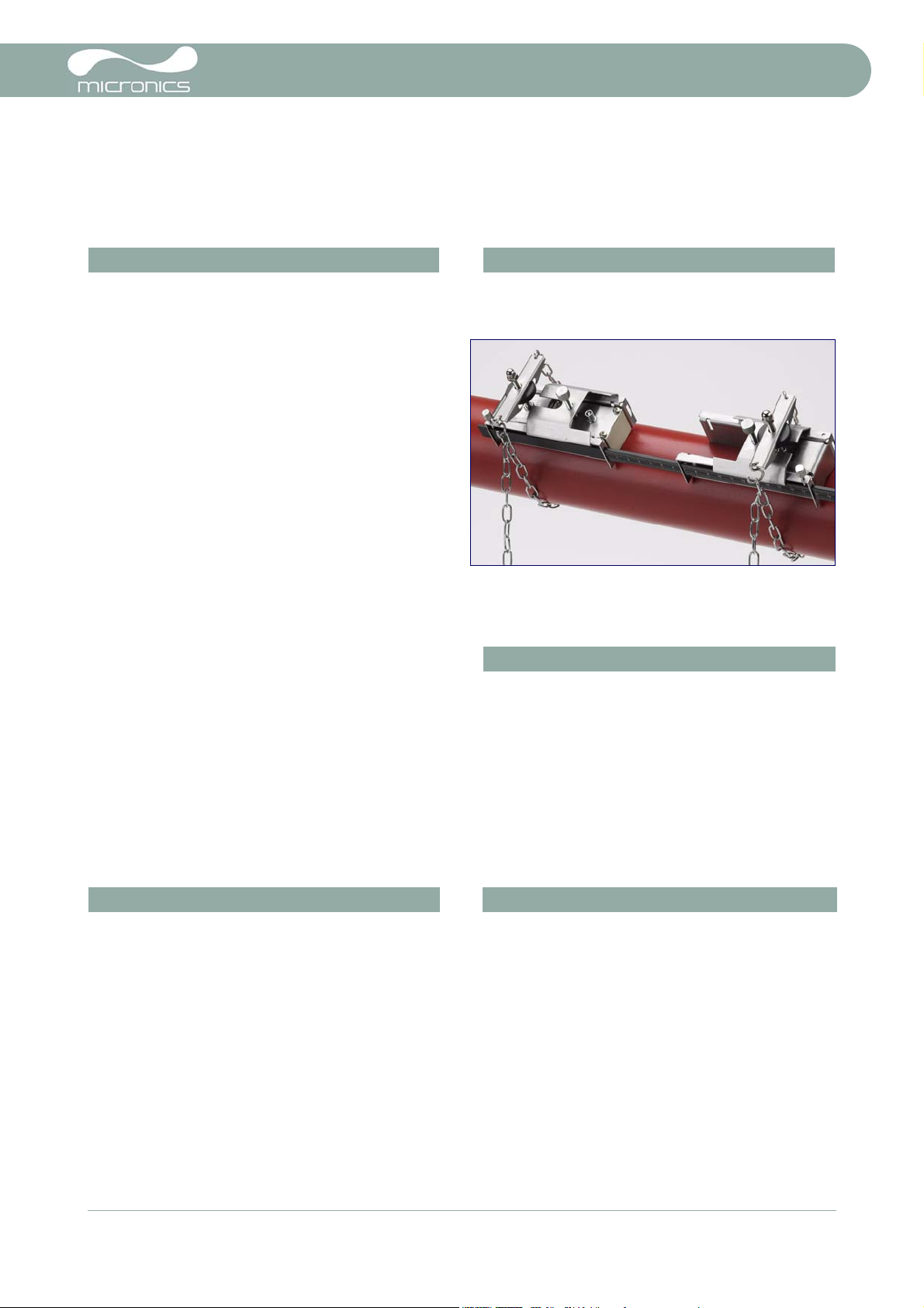
Transducer mounting
Type ‘A’ & ‘B’ transducers are fitted to adjustable guide rails
which are secured to the pipe using wrap-around chains and
mechanically connected together by a steel separation bar. The
separation bar also acts as a ruler to allow the distance between
the transducers to be set to the value calculated by the
Portaflow instrument.
A thumb-wheel is used to adjust the chain tension until the
assembly is held firmly in place. The transducers are then
inserted into the guide rails and secured in place by a knurled
screw. This illustration shows a completed assembly with a
transducer fitted to the left-hand guide rail only.
The transducers are connected to the PF220 instrument by
means of two 2m mini-coaxial cable.
Control Outputs
The PF220 provides analogue and pulse outputs that are
designed to be used in conjunction with external control and
site monitoring applications such as those typically found in
building management systems. These outputs can be
calibrated to suit a required flow operating range and a highflow alarm level.
Both outputs are connected to a single (green), 7-pin LEMO
socket located on the top of the PF220 instrument. A single
2 metre cable is provided that can be adapted for use for
either of these output functions. The ‘tails’ on the free end of
the cable must be terminated to suit the intended application
Analogue output: Pulse output:
Range – 4–20mA
0–20mA
0–16mA
Resolution – 0.1% of full scale Pulse repetition – Up to 500 pulses/sec (depending on
Alarm current –
Isolation –
Maximum load –
Adjustable between 0–26mA Pulse width – 500ms for 1pulse/s
1500V Opto-isolated Max current – 150mA
620 Ohms
Cable termination
Red –
Black –
White –
Green –
Brown –
Blue –
Thick Black –
Output type – One open collector opto-isolated digital
4-20mA positive
4-20mA negative
Pulse output (+)
Pulse return (-)
Set Point (not in present use)
Set Point return (not in present use)
Cable screen
output
pulse width)
5ms for 100 pulses/s
Portaflow 220 Technical Datasheet 5
(Issue 1.0)
Page 6

Portaflow 220 Technical Datasheet
Technical data
General specification:
DSP measurement technique – The PF220 uses ‘transit time’ measurement with a sampling resolution of 50 pico-
second, with a continuous signal level indication to the display
Flow velocity range (bi-directional) – • Minimum velocity 0.1m/s
• Max velocity 20m/s
Flow measurement accuracy – • ±0.5% to ±2% of flow reading for flow rate >0.2m/s and Pipe ID >75mm
• ±3% of flow reading for flow rate >0.2m/s and Pipe ID in range 13mm - 75mm
• ±6% of flow reading for flow rate < 0.2m/s
•
Flow velocity corrected for Reynolds number over entire velocity range
Repeatability – • ±0.5% of measured value or ±0.02m/s whichever is the greater
Response time – • < 500ms depending on pipe diameter
Selectable flow units –
Selectable volume units – • l, gal, USgals, Barrel, m³
Total volume – • 12 Digits - forward and reverse
Display languages – The following operator languages can be selected from the PF220 set-up menu
• VELOCITY: m/sec, ft/sec
• VOLUME: l/s, l/min, l/h, gal/min, gal/h, USgals/min, USgals/h, Barrel/h,
Barrel/day, m³/s, m³/min, m³/h
• English
• French
• German
• Italian
• Spanish
• Portuguese
• Russian
• Norwegian
• Dutch
Electrical
Supply voltage: Power supply charger:
Input voltage range –
Power consumption –
Battery:
Technology – 5-cell NiMH Output voltage – 12Vdc
Capacity – 3.8AHr Max. Output current – 1.5A
Operating time – Typically 20 hours continuous with
Recharge time – 6.5 Hours
Service life – >500 charge/discharge cycles
9–24Vdc
10.5W
backlight and 4-20mA output OFF
Manufacturer – Model ECO-181WP12
Input voltage range – 90–264Vac
Input frequency range – 47–63Hz
Approvals – UL, CUL, TUV, CB & CE
6 Portaflow 220 Technical Datasheet
(Issue 1.0)
Page 7
Portaflow 220 Technical Datasheet
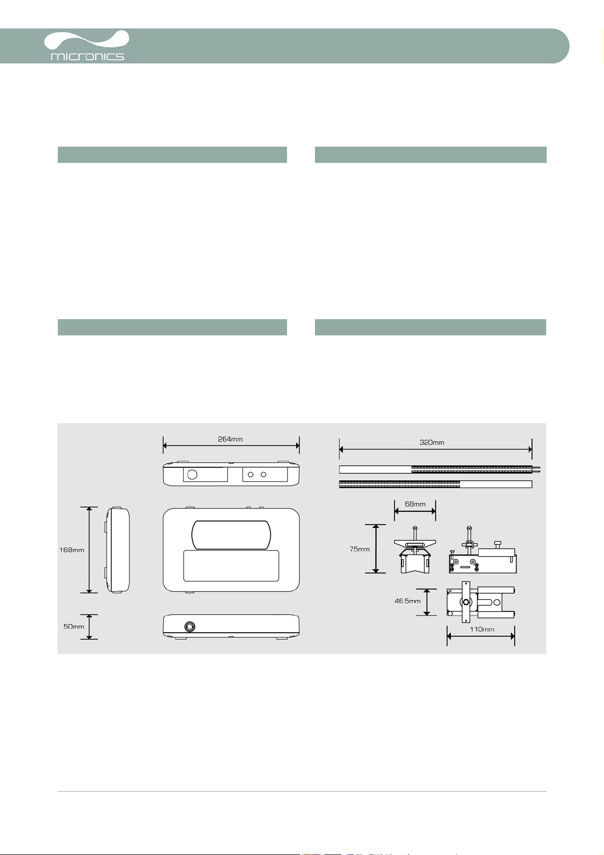
Mechanical & miscellaneous data
All components are contained in a hard-wearing polypropylene carrying case with a protective moulded foam insert.
Instrument enclosure: Shipping information:
Material – Flame retardant injection moulded
ABS
Dimensions – 264mm x 168mm x 50mm Weight – 6.0 kg
Weight – 1.1 kg (including battery) EMC – BS EN 61326 - 1:2006,
Number of Keys – 16 Volumetric weight – 4.5 kg
Display – 240 x 64 pixel graphic display, high
contrast black-on-white, with
backlight
Viewing angle: Min 30°, typically 40°
Box dimensions – 505mm x 125mm x 420mm
BS EN 61326-2-3:2006
Environmental: Approvals:
Operating temperature – -20°C to +50°C Safety –BS EN 61010
Storage temperature – -25°C to +65°C Battery charger – EN61204 - 3
Operating humidity – 90% RH MAX at +50°C EMC – BS EN 61326 - 1:2006,
BS EN 61326-2-3:2006
Dimensions
Micronics reserve the right to alter any specification without notification.
PORTAFLOW™ 220 and PF220 are identical.
Portaflow 220 Technical Datasheet 7
(Issue 1.0)
Page 8

Portaflow 220 Technical Datasheet
8 Portaflow 220 Technical Datasheet
(Issue 1.0)
 Loading...