

Page 1
A.H. Systems, inc.
INTRODUCTION
A.H. Systems' Preamplifier line is an
excellent choice with a rugged
design, no hassles with soldering
your own power leads and they
improve overall system sensitivity
by at least 20 dB. All of the
Preamplifiers come with a 12-volt
(or 15-volt) DC regulated power
source. A low voltage indicator
confidently allows you to power the
amplifier with your own external 12volt DC battery. This makes it a
convenient choice for field
measurements.
INTENDED PURPOSES
This equipment is intended for
general laboratory use in a wide
variety of industrial and scientific
applications and is designed to be
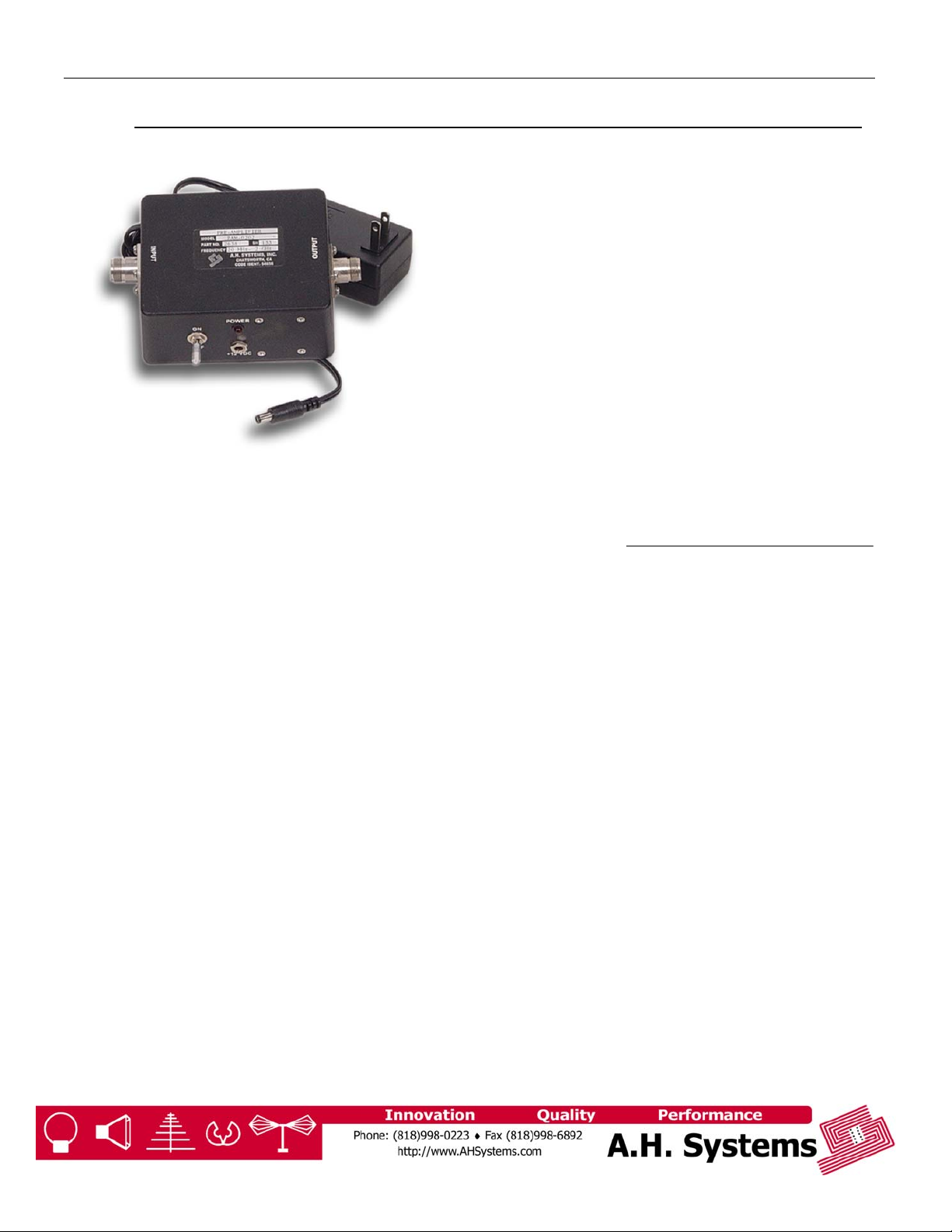
Model: PAM-0118
FEATURES:
Wide Bandwidth (20 MHz – 18 GHz)
Low Noise, High Gain
Individually Calibrated
Low VSWR
Improve Overall System Sensitivity
Rugged Design
used in the process of generating,
controlling and measuring high
levels of electromagnetic Radio
Frequency (RF) energy. Therefore,
the output of the amplifier must be
connected to an appropriate load
such as an antenna, fieldgenerating device or receiver. It is
the responsibility of the user to
assure that the device is operated in
a location which will control the
radiated energy such that it will not
cause injury and will not violate
regulatory levels of electromagnetic
interference.
HAZARDOUS RF VOLTAGES
The RF output connector should be
connected to a load before AC
power is applied to the amplifier.
Model PAM-0118 Preamplifier
RECOMMENDED ACCESSORIES
SAS-571 Double Ridge Guide
Horn Antenna
SAC-18G-3 Low-Loss, High
Frequency Cables
SAS-571 Double Ridge Guide
Horn Antenna
Page 2

A.H. Systems, inc.
(dB)
RANGE OF ENVIRONMENTAL CONDITIONS
This equipment is designed to be safe under the following environmental conditions:
While the equipment will not cause hazardous conditions over this environmental range,
performance may vary.
Model PAM-0118 Preamplifier
• Indoor use
• Altitude up to 2000M
• Temperature of 5°C to 40°C
• Maximum relative humidity 80% for temperatures up to 31°C.
Decreasing linearly to 50% at 40°C
• Mains supply voltage fluctuations not to exceed +/- 10% of the
nominal voltage or minimum and maximum autoranging values.
• Pollution degree 2: Normally non-conductive with occasional
condensation.
Preamplifier
Gain
Frequency Response (Typical)
Page 3

A.H. Systems, inc.
SPECIFICATIONS
The PAM-0118 Preamplifier Specifications:
Power output ............................................................... +10 dBm at 1 dB compression
Frequency Range .............................................................................20 MHz - 18 GHz
Maximum input for rated output ......................................................................-30 dBm
Gain ..................................................................................................................38.0 dB
Gain Flatness ............................................................................................... +/- 2.5 dB
Noise Figure................................................................................................2.5 dB Max
Modulation capability............................................................will reproduce AM, FM or
Primary Power .................................................................................+15 VDC, 110 mA
RF Connectors....................................................................................Type N (female)
Impedance..................................................................................50 ohm, < 2.5 VSWR
Weight ..................................................................................................1.1 lbs. / 0.5 kg
Size (W x H x D) .............................................................................3.75" x 2.5" x 6.25"
...........................................................................
POWER SUPPLY
The model PAM-0118 is
supplied with an external power
supply that can be used on
110/120/220/240 VAC, 50/60
Hz, and supplies 15.0 VDC at
180 mA. The power supply has
a standard AC input connector
and uses a 2.5mm coax output
connector. An optional battery
source may be used for this unit.
GENERAL USE INSTRUCTIONS
Operation of the model PAM0118 low noise amplifier is quite
simple. The unit is turned on by
first plugging the phone type
plug from an external power
supply into the power input
connector. The power supply is
then plugged into the
appropriate line voltage supply.
The input signal is connected to
the jack marked “INPUT”. The
output signal is taken from the
jack marked “OUTPUT” and fed
to the desired amplifier or test
equipment. When the
preamplifier is turned on the
power indicator LED will light.
Please allow 15 minutes of
warm up time to allow the
preamplifier to stabilize. The
input signal should always be at
a level of –30 dBm or lower.
Signal levels greater than –30
dBm will drive the amplifier into
compression, resulting in
distortion of the signal.
CAUTION:
The model PAM-0118
amplifier is not critical in
regards to source and load
VSWR and will remain
unconditionally stable with
any magnitude and phase of
source and load VSWR.
Annual recalibration is
recommended to ensure reliable
and repeatable performance.
A.H. Systems experienced
technicians can recalibrate
almost any type or brand of
antenna.
For more information about our
calibration services or to place
an order for antenna calibration
visit our website at
http://www.AHSystems.com or
call 1(818) 998-0223.
Model PAM-0118 Preamplifier
pulse modulation on the
input signal
95.3 x 63.5 x 158.7 mm
However, input signals
greater than +10 dBm can
damage the amplifier.
MAINTENANCE
 Loading...