

Page 1
Description
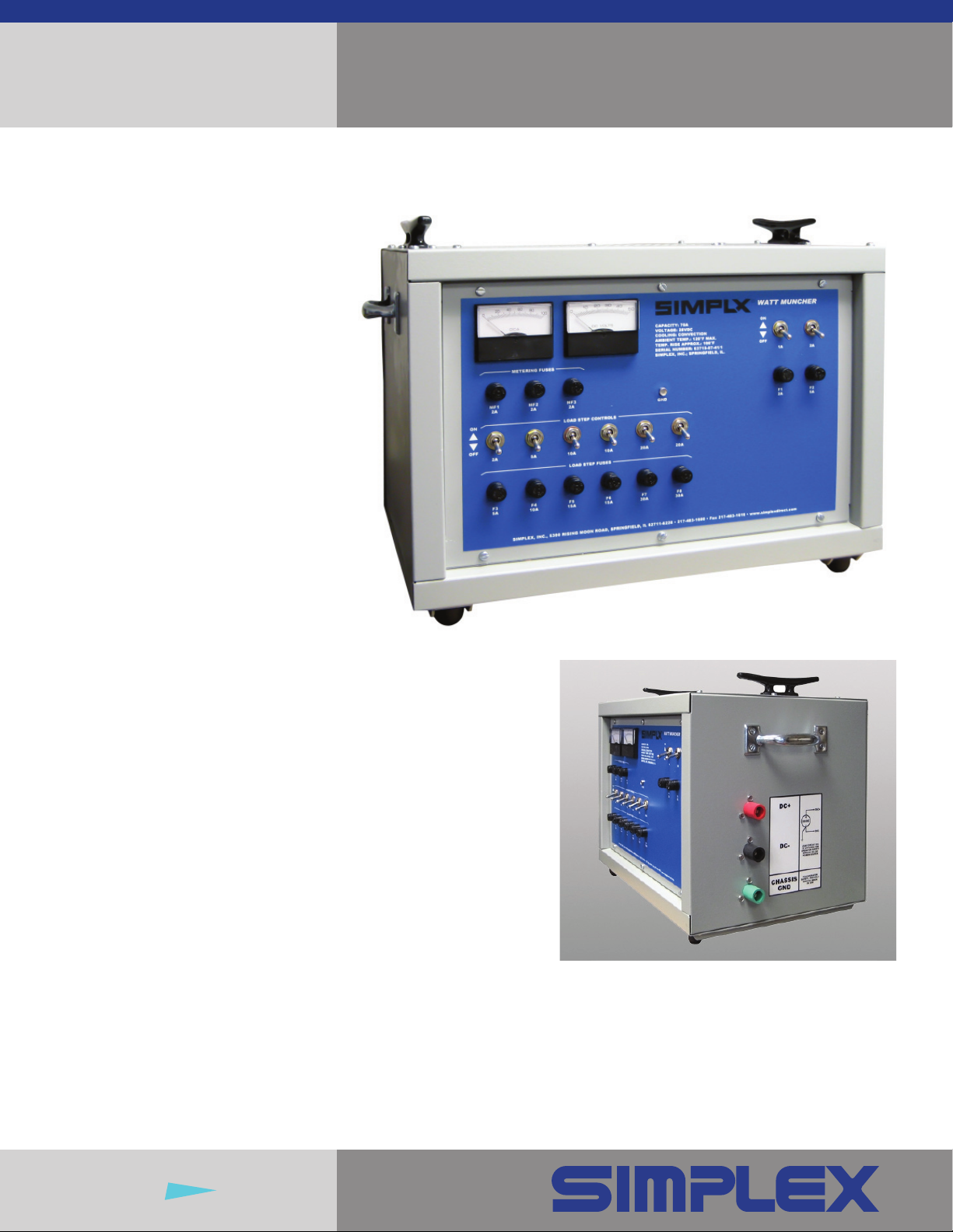
The Simplex Watt-Muncher is a
small DC rated load bank used to test
battery systems, AC to DC rectifi ers
and power supplies, battery chargers,
UPS systems and DC generators.
The Watt-Muncher provides a variable
test load used to measure charge and
discharge rates, response, stability and
endurance. Corresponding calibrations
and adjustments can be made while
maintaining a constant, precise, resistive
load on the power source. The WattMuncher is available in three nominal
voltage ranges and three capacity
models. In each model, the total load is
divided into discrete steps that can be
manually applied in any increment of 1A.
Watt-Muncher
DC Portable Load Bank
Watt-Munchers are assembled
using the highest quality industrial
components including:
• chromium alloy load elements rigidly
supported by high temperature
ceramic clad insulators
• heavy duty terminals
• industrial toggle switches
• fast acting fuses
• high temperature XLP insulated power
wiring
• precise instruments
Watt-Munchers can be operated within
their rating continuously. The load
resistors used in the Watt-Muncher
convection cool to less than one-third
the maximum, continuous temperature
rating of the chromium alloy resistance
wire. Fuses on each load step protect
the load bank against overvoltage and
short circuit.
Fully self-contained, lightweight and
hand transportable, the Watt-Muncher
is the ideal addition to your selection of
test instruments.
Watt-Munchers are available
with three nominal voltages:
• 12V DC
• 24V DC
• 32V DC
in three models:
• Junior (70A)
• Standard (100A)
• Super (150A)
Insight
Onsite
®
Page 2

Watt-Muncher
DC Portable Load Bank • Page 2
®
Resistive Load
Simplex “Powr-Web” iron-chromiumaluminum alloy power resistors
operating at 312°C, rated for maximum
continuous 1038°C; continuously
supported by high temperature ceramic
clad insulators
Load Step Control
Manual toggle switches, 1A resolution
Load Resistor Overvoltage/
Short Circuit Protection
One fuse per step
Cooling
Convection
Power Wiring
150°C XLP insulated
Load Termination
Positive and negative bus bar
Options
• DC Voltmeter
• Special Terminals
• Non-Standard Voltages, Dual
Voltages
• Variable Step
Key Features and
Dimensions
1. Ammeter
2. Metering Fuses
3. Control Toggle Switches
4. Cable Cleats
5. Carry Handles
6. Rubber Feet
7. Load Step Toggle Switches and Fuses
8. Cam-Lok Type Connectors
Instrumentation
2% accuracy, 2.5” square, DC ammeter
Enclosure
16 gauge steel frame, sides and control
panel. Screened top, back and bottom.
Handles on each end. Rubber feet.
Junior Standard Super
Capacity 70A 100A 150A
Voltage 12/24/32 V DC 12/24/32 V DC 12/24/32 V DC
(Specify One) (Specify One) (Specify One)
Load Steps (1) 1A (1) 1A (1) 1A
These load steps are
(2) 2A (2) 2A (2) 2A
for example only. Actual
load steps depend on
(1) 5A (1) 5A (1) 5A
specified voltage and
may vary.
(6) 10A (9) 10A (1) 10A
(2) 15A
(4) 25A
Temp. Rating 50°C Ambient 50°C Ambient 50°C Ambient
Weight 30 lbs 40 lbs 55 lbs
Simplex, Inc.
5300 Rising Moon Road
Springfi eld, IL 62711-6228
217-483-1600
Fax 217-483-1616
www.simplexdirect.com
© 2011 Simplex, Inc. All Rights Reserved.
Printed in the USA • 1102-12.00
Design subject to change without notice.
 Loading...