

Page 1
LINE IMPEDANCE STABILIZATION NETWORKS
APPLICATION
When measuring conducted radio interference
voltages from active power lines to ground, it is
essential to know the line impedance so that
repeatable tests can be made by more than one
laboratory.Artificial line impedances are specified
in MIL-STD-462, V.D.E., C.I.S.P.R., C22.4, NACSEM
5100, ANSI C63.2 and other EMI specifications.
The characteristic impedance of the five
microhenry and 50 microhenry LISNs brackets
the mean value of power line impedance which
has been measured by independent researchers.
These two inductance values in parallel with
the 50 ohms of the EMI meter fall between the
minimum and maximum line impedance values
which have been measured. The mean value
would be represented by a twenty microhenry
inductor in parallel with100 ohms.
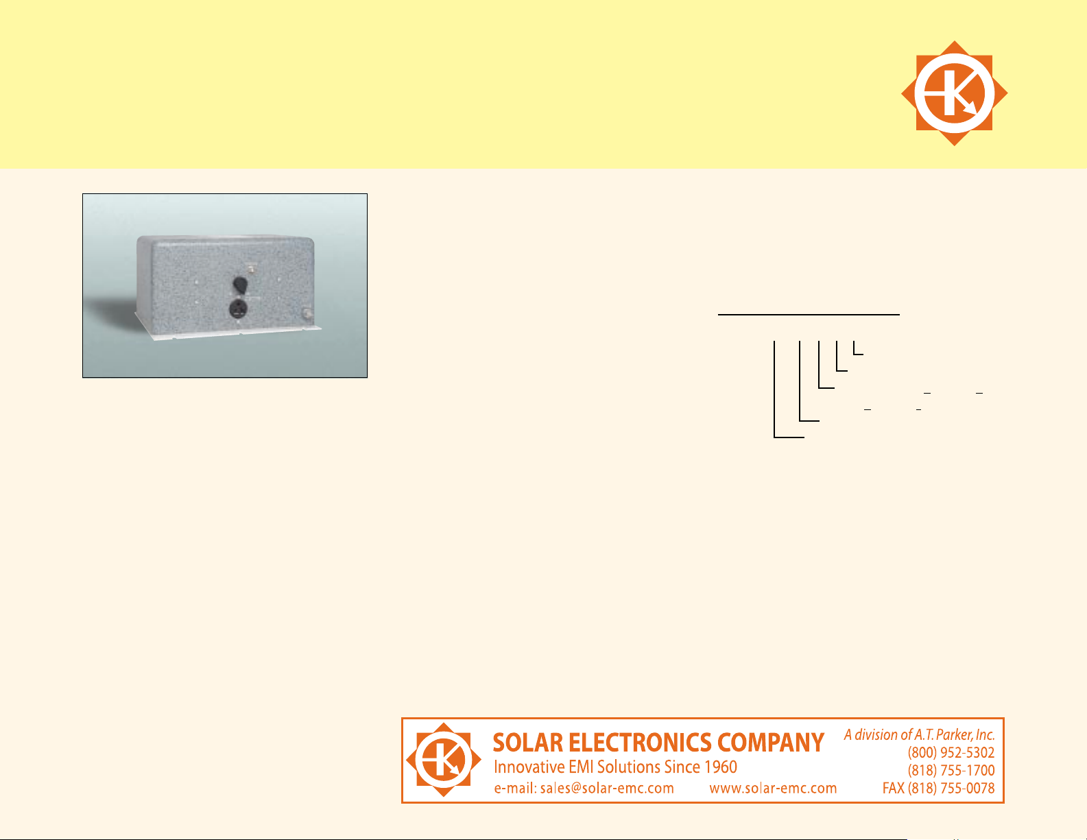
DESCRIPTION
The Solar Electronics LISNs use a series inductor
between the test sample and the power source
to provide the impedance-versus-frequency
characteristic. A coaxial connector with d.c.
isolation is provided for connection to the
associated frequency selective EMI meter. The
power source end of the inductor is bypassed
to ground.
Due to the large current-carrying capability of
some LISNs, it is not always practical to use
a switch for changing inductance values.
Instead, some models are equipped with a high
current pin plug-and-jack combination for quickly
connecting and disconnecting a network and
substituting another.This nylon insulated pin plug
and jack arrangement is a safety feature, well
isolated from inadvertent short circuits, providing
protection to operating personnel.
Current ratings up to 200 amperes are available in
50 H styles and 500 amperes in 5 H styles. See
the chart on the following page.
When measurements are made in a shielded
room, the LISNs intended for F.C.C. applications
will also serve for V.D.E. tests.When operating on
an unfiltered power line, the V.D.E. specifications
require a filter consisting of 250 microhenry
inductor and a capacitor.This filter is included in
the 24 ampere LISN, Type 9348-50-R-24-BNC,
and the 50 ampere LISN, Type 8602-50-TS-50-N.
EMI specifications require one LISN in each
ungrounded power lead.Even though the neutral
is considered “ground,” if it is not connected to
chassis inside the unit under test, the lead must
be tested with an LISN. Therefore, use two LISNs
in d.c.or single phase a.c. applications, three LISNs
for delta-connected three phase circuits,and four
LISNs for ‘Y’ connected three phase circuits.
Explanation of Type Numbers
8602-50-TS-50-N
R.F. connector style
Current rating,amperes
Terminals: TS = T
erminal Screw
PJ = P
lug and Jack
Series inductance, microhenries
Basic model number
37
Page 2
LINE IMPEDANCE STABILIZATION NETWORKS
Current Inductance Line/Ground Voltage Case
Type Number Amps H 50-60 Hz 400 Hz Size* Circuit Frequency Range
6516-5-TS-10-BNC 10 5 270 130 #5 Single 150 KHz- 65 MHz
6516-57-TS-10-BNC 10 57 270 130 #6 Single 14 KHz- 4 MHz , 0.1f coupling capacitor
8012-50-R-24-BNC 24 50 135 N/A #1 Dual 10 KHz- 50 MHz , 0.1f coupling capacitor
8028-50-TS-24-BNC 24 50 270 130 #1 Single 10 KHz- 50 MHz
8116-50-PJ-100-N 100 50 270 130 #3‡ Single 10 KHz- 30 MHz
8116-50-TS-100-N 100 50 270 130 #3‡ Single 10 KHz- 50 MHz
8309-5-PJ-100-N 100 5 500 240 #3 Single 150 KHz- 65 MHz
8309-5-TS-100-N 100 5 500 240 #3 Single 150 KHz- 65 MHz
8328-50-PJ-50-N 50 50 270 130 #3 Single 10 KHz- 30 MHz, 0.1f coupling capacitor
8328-50-TS-50-N 50 50 270 130 #3 Single 10 KHz- 50 MHz, 0.1f coupling capacitor
8410-250-R-24 24 250 270 130 #1 Dual 250H choke network with AC receptacle for use
with 8012-( ) and 9252-( ) for VDE applications
8602-50-PJ-50-N 50 50 270 130 #4 Single 10 KHz- 30 MHz w/ 250H choke
8602-50-TS-50-N 50 50 270 130 #4 Single 10 KHz- 50 MHz w/ 250H choke
8610-50-PJ-100-N 100 50 500 240 #3‡ Single 10 KHz- 30 MHz
8610-50-TS-100-N 100 50 500 240 #3‡ Single 10 KHz- 30 MHz
8611-50-TS-10-N 10 50 270 130 #2 Single 10 KHz- 30 MHz w/ 250H choke
8615-2-TS-100-N 100 2 270 130 #1 Single 1 MHz- 1 GHz , 0.1F coupling capacitor
8616-5-PJ-200-N 200 5 270 130 #3‡ Single 150 KHz- 65 MHz
8616-5-TS-200-N 200 5 270 130 #3‡ Single 150 KHz- 65 MHz
8616-50-PJ-200-N 200 50 270 130 #3‡ Single 10 KHz- 30 MHz
8616-50-TS-200-N 200 50 270 130 #3‡ Single 10 KHz- 50 MHz
8902-5-TS-500-N 500 5 500 240 #4 Single 150 KHz- 1 GHz
*Case Sizes (w x h x l) #3: 10.37" x 9.12" x 13" (26.35 cm x 23.18 cm x 33 cm)
Add 3" (7.62 cm) for Base Plate #4: 7.53" x 7.63" x 18.97" (19 cm x 19.43 cm x 48.26 cm)
‡ With 50 or 60 Hz Ventilating Fan; add 7.09" (18.00 cm) #5: 3.12" x 1.75" x 3.87" (7.94 cm x 4.44 cm x 9.84 cm)
#1: 5.12" x 5.12" x 10" (13 cm x 13 cm x 25.4 cm) #6: 2.75" x 2.45" x 5.7" (6.98 cm x 6.22 cm x 14.48 cm)
#2: 7.0" x 7.0" x 8.25" (17.78 cm x 11.78 cm x 24.13 cm) #7: 13.37" x 7.25" x 13.25" (33.97 cm x 18.41 cm x 33.65 cm)
Note: Unless otherwise specied, 5µH LISN’s have 0.1f coupling caps; 50µH have 0.25f coupling caps
38
Page 3
LINE IMPEDANCE STABILIZATION NETWORKS (cont.)
Current Inductance Line/Ground Voltage Case
Type Number Amps H 50-60 Hz 400 Hz Size* Circuit Frequency Range
8905-50-TS-50-N 50 50 270 130 #3 Single 10 KHz- 200 MHz
8907-250-TS-24 24 250 270 130 #1 Dual 250H choke network with binding posts.
For use with two 8028-( ) for VDE applications
9117-5-PJ-50-N 50 5 500 240 #1 Single 150 KHz- 1 GHz
9117-5-TS-50-N 50 5 500 240 #1 Single 150 KHz- 1 GHz
9233-50-PJ-50-N 50 50 270 130 #3 Single 10 KHz- 50 MHz
9233-50-TS-50-N 50 50 270 130 #3 Single 10 KHz- 50 MHz
9247-50-TS-50-N 50 50 500 240 #3 Single 10 KHz- 50 MHz, 0.1F coupling capacitor
9252-50-R-24-BNC 24 50 270 130 #7 Dual 10 KHz- 50 MHz
9322-50-R-10-BNC 10 50 270 130 #7 Dual 10 KHz- 50 MHz
9331-50-PJ-200-N 200 50 500 240 #3‡ Single 10 KHz- 30 MHz
9331-50-TS-200-N 200 50 500 240 #3‡ Single 10 KHz- 50 MHz
9345-5-R-10-BNC 10 5 135 N/A #1 Dual 150 KHz- 65 MHz
9348-50-R-24-BNC 24 50 270 130 #7 Dual 10 KHz- 50 MHz with 250H choke
9351-5-TS-200-N 200 5 500 240 #3‡ Single 100 KHz- 1 GHz, 150 impedance
9403-5-TS-10-BNC 10 5 270 130 #5 Single 150 KHz- 65 MHz
9408-50-R-24-BNC 24 50 500 240 #7 Dual 10 KHz- 50 MHz
9409-50-R-24 24 50 135 N/A #2 Dual 6 Output Auxiliary, no RF connector
9509-50-R-24-BNC 24 50 500 240 #7 Dual 10 KHz- 50 MHz w/ 250H choke
9517-50-R-10-BNC 10 50 270 130 #7 Dual 10 KHz- 50 MHz w/ 250H choke
9608-50-BP-10-BNC 10 50 500 240 #7 Dual 10 KHz- 50 MHz, binding posts, no switch
9615-50-R-25-BNC 25 50 270 130 #7 Dual 10 KHz- 30 MHz, air coil
9622-50-BP-10-BNC 10 50 500 240 #1 Single 10 KHz- 50 MHz
9623-50-TS-25-BNC 25 50 270 130 #1 Single 10 KHz- 30 MHz, air coil
9629-50-TS-25-BNC 25 50 500 240 #1 Single 10 KHz- 30 MHz
*Case Sizes (w x h x l) #3: 10.37" x 9.12" x 13" (26.35 cm x 23.18 cm x 33 cm)
Add 3" (7.62 cm) for Base Plate #4: 7.53" x 7.63" x 18.97" (19 cm x 19.43 cm x 48.26 cm)
‡ With 50 or 60 Hz Ventilating Fan; add 7.09" (18.00 cm) #5: 3.12" x 1.75" x 3.87" (7.94 cm x 4.44 cm x 9.84 cm)
#1: 5.12" x 5.12" x 10" (13 cm x 13 cm x 25.4 cm) #6: 2.75" x 2.45" x 5.7" (6.98 cm x 6.22 cm x 14.48 cm)
#2: 7.0" x 7.0" x 8.25" (17.78 cm x 11.78 cm x 24.13 cm) #7: 13.37" x 7.25" x 13.25" (33.97 cm x 18.41 cm x 33.65 cm)
Note: Unless otherwise specied, 5µH LISN’s have 0.1f coupling caps; 50µH have 0.25f coupling caps
39
Page 4

LINE IMPEDANCE STABILIZATION NETWORKS (cont.)
Current Inductance Line/Ground Voltage Case
Type Number Amps H 50-60 Hz 400 Hz Size* Circuit Frequency Range
9702-50-TS-100-N 100 50 270 130 call Single 10 KHz- 50 MHz w/ 250H choke
9706-5-TS-250-N 250 5 270 130 #3 Single 150 KHz- 65 MHz
9845-50-BP-10-BNC 10 50 135 N/A #1 Dual 10 KHz- 30 MHz, binding posts, no switch
9847-50-TS-50-N 50 50 270 130 #3 Single with 20F capacitor
9857-50-BP-24-BNC 24 50 135 120 #1 Dual 10 KHz- 50 MHz, binding posts, no switch
9861-50-BP-24-BNC 24 50 270 130 #7 Dual 10 KHz- 50 MHz, binding posts, no switch
9867-5-TS-50-N 50 5 270 130 #2 Single 1 KHz- 400 MHz w/ 10F capacitor
9911-50-R-10-BNC 10 50 135 N/A #1 Dual 10 KHz- 50 MHz
9913-50-TS-10-BNC 10 50 270 130 #7 Dual 10 KHz- 50 MHz, 6-32 threaded terminals
9924-5-TS-100 100 5 270 130 #3 Isolated 100 KHz- 100 MHz (ISO 7637-2)
2119-5-TS-50-N 50 5 270 130 #1 Single 10 KHz- 120 MHz CISPR 25 (1995-11)
CISPR 1612, CISPR 22, FCC, ANSI C63.4
21105-50-BP10BNC 10 50 270 135 #1 Single 150 KHz- 30 MHz
21106-50-BP25BNC 25 50 270 135 #1 Single 150 KHz- 30 MHz
21107-50-TS50N 50 50 270 135 #3 Single 150 KHz- 30 MHz
21107-50-PJ50N 50 50 270 135 #3 Single 150 KHz- 30 MHz
21108-50-TS100N 100 50 270 135 #3‡ Single 150 KHz- 30 MHz
21108-50-PJ100N 100 50 270 135 #3‡ Single 150 KHz- 30 MHz
21114-50-TS50N 50 50 500 240 #3 Single 150 KHz- 30 MHz
21114-50-PJ50N 50 50 500 240 #3 Single 150 KHz- 30 MHz
21114-50-TS100N 100 50 500 240 #3‡ Single 150 KHz- 30 MHz
21114-50-PJ100N 100 50 500 240 #3‡ Single 150 KHz- 30 MHz
*Case Sizes (w x h x l) #3: 10.37" x 9.12" x 13" (26.35 cm x 23.18 cm x 33 cm)
Add 3" (7.62 cm) for Base Plate #4: 7.53" x 7.63" x 18.97" (19 cm x 19.43 cm x 48.26 cm)
‡ With 50 or 60 Hz Ventilating Fan; add 7.09" (18.00 cm) #5: 3.12" x 1.75" x 3.87" (7.94 cm x 4.44 cm x 9.84 cm)
#1: 5.12" x 5.12" x 10" (13 cm x 13 cm x 25.4 cm) #6: 2.75" x 2.45" x 5.7" (6.98 cm x 6.22 cm x 14.48 cm)
#2: 7.0" x 7.0" x 8.25" (17.78 cm x 11.78 cm x 24.13 cm) #7: 13.37" x 7.25" x 13.25" (33.97 cm x 18.41 cm x 33.65 cm)
Note: Unless otherwise specied, 5µH LISN’s have 0.1f coupling caps; 50µH have 0.25f coupling caps
40
 Loading...