

Page 1
Product Features
LDC
Mainframe
16 independent channels,
with 32 isolated outputs
“Smart” modules for exibility and speed
Laser Current Sources
High compliance voltage
Direct modulation up to 1.2 MHz
Four-wire measurement of laser diode
forward voltage
Advanced laser protection features
including adjustable voltage limit
TEC Controllers
TEC voltage measurement
Resistive heater control adapters
available
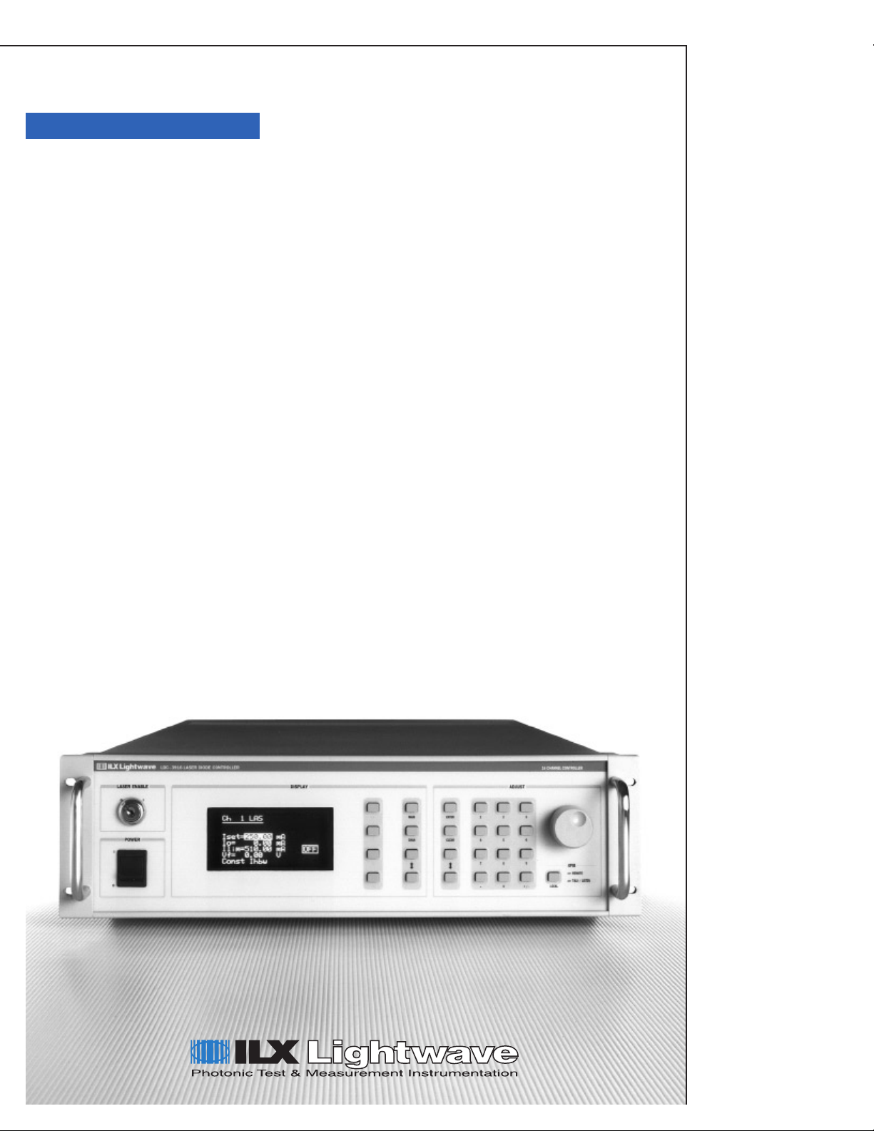
The LDC-3916 16-Channel Laser Diode Controller
packs 16 channels of laser diode current source and tem-
perature control into a space-saving 3U-high instrument.
An on-board processor powers each module, simplifying
future module additions and accelerating performance. A
variety of “smart” modules are available. These include
controller modules with up to 1.5 A of laser current source,
with 9 W of TEC control; dual laser current source mod-
ules with two isolated currents of up to 1 A; a dual 9
W TEC module; a 3 A laser current module; and 3 A
24 W TEC module. Additional modules are currently in
development.
An independent, isolated power supply powers each
module, delivering unparalleled stability. This design
brings even greater levels of laser diode protection
through our adjustable compliance voltage feature. Com-
munications and instrument operations are controlled
by a separate mainframe processor, paired with a
powerful GPIB chipset that is fully tested to ensure
IEEE 488.2 compliance.
3916
16-Channel
Laser Diode
Controller
16 Channels of Laser Diode Control
Page 2

LDC
3916
16-Channel
Laser Diode
Controller
Front Panel Interface
Provides Simple Operation
The front-panel interface features a bright
vacuum uorescent display, making the
information readable from almost any angle.
You can easily monitor the operations of up to
four channels at a time. Simple and intuitive
menus, supported by screen-specic soft-keys,
allow you to quickly congure and operate each
channel. Menu depths have been intentionally
limited to keep the front-panel operation con-
cise, while more sophisticated operations are
reserved for the GPIB interface. Setpoints and
other values can be entered through your choice
of numeric keypad entry, up-down arrow keys, or
a rotary adjustment knob.
Powerful GPIB Interface Offers
Robust, Automated Control
A powerful processor platform drives the
LDC-3916 16-Channel Laser Diode Controller.
When coupled with the latest GPIB technology
from National Instruments’ HS488 TNT chipset,
you get all the processing capability needed for
mission-critical production testing. With micro-
processors on each module, the mainframe
engine manages 16 independent control chan-
nels quickly and reliably. Free LabVIEW®
instrument drivers are available upon request,
or by downloading them at
www.ilxlightwave.com.
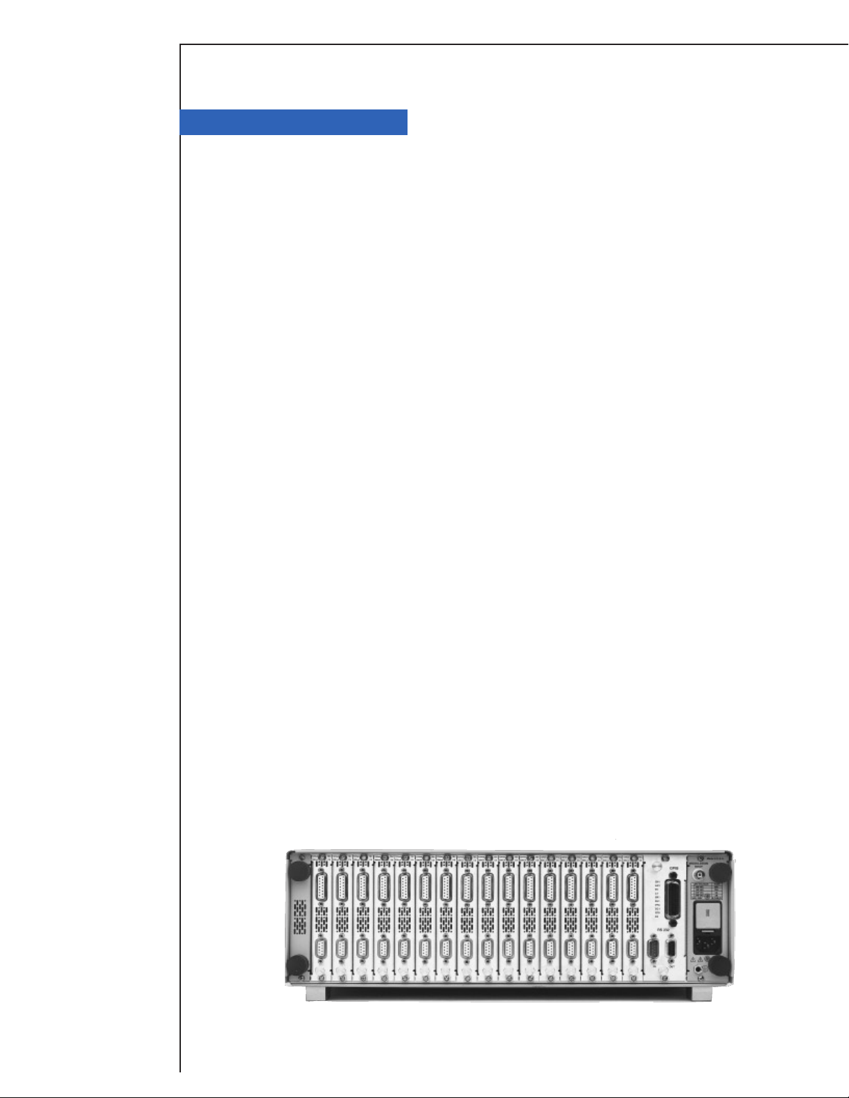
High Performance Modules
Support Future System Expansion
Designed to provide the cleanest, safest
power available for laser diode control, each
module’s control functions are handled locally
and communicated quickly to the host pro-
cessor. On-board intelligence simplies future
addition of modules since all operational and
calibration data is stored in the module. Simply
plug in your new module and power up the
system. Your mainframe never needs to leave
the rack. This simplicity, coupled with low-noise,
high-stability outputs and state-of-the-art laser
diode protection, equals ultimate performance.
State-of-the-Art Current Source
Design Brings New Levels
of Performance
This new current source topology uses an
innovative, proprietary control loop and incorpo-
rates the latest techniques for signal ltering and
circuit board shielding. These advancements
provide unbeatable stability and unparalleled
noise performance, ideal for the most demand-
ing production test applications. This design
also incorporates adjustable compliance voltage
and faster shutoff, helping prevent dangerous
“reconnect” transients that can occur from inter-
mittent connections between the controller and
your laser diode. This new level of protection
adds to our proven list of protection features:
independent current limits, output shorting cir-
cuits and a slow-start turn-on feature.
New Capabilities from the
Flexible Current Source You Trust
Operational modes including constant cur-
rent, constant current high-bandwidth, or
constant optical power are selectable from the
front panel, or via the GPIB interface. Mea-
surement of your laser diode’s forward voltage
is possible with 4-wire accuracy, which can be
helpful in production environments where longer
cable runs are common. A single, rear-panel
modulation port can individually enable direct
modulation of each channel’s laser current. This
new current source design supports modulation
bandwidths of up to 1.2 MHz (small signal),
achieving the highest direct modulation
Page 3

High channel-density laser diode
control for production test.
LDC
3916
16-Channel
Laser Diode
Controller
levels available today. Modules also include
reverse photodiode bias capabilities, especially
important for telecom wavelength devices.
High-Stability TEC Control Keeps
Your Device Temperature in Check
Equipped with a smart integrator control loop
and an expanded gain setting range, the tem-
perature control circuits optimize settling times.
These modules also provide voltage measure-
ment of your TEC, and allow internal selection
of thermistor current ranges via front-panel or
via GPIB. Achieve unparalleled temperature
stabilities with ultra-stable design topology and
low-noise bipolar output stages.
Flexible Control Over a
Wide Range of Applications
By combining true modularity with high chan-
nel density, the LDC-3916 easily grows with your
applications. When coupled with our 16-channel
mounting tray, this controller also serves as a
cost effective DWDM optical source set. Simply
mount your choice of WDM DFB laser
diodes in the mounting tray, connect to the
controller, and you’ll have full control over
16 WDM signal sources. If your specied test
wavelengths change, simply drop in new DFB
laser diodes. For even higher channel counts,
add another controller and mounting tray to your
rack. If your device drive specications change,
look to ILX Lightwave for new modules that can
be easily added to your system in the future.
Protect Your Investment with the
Leader in Laser Diode Protection
The LDC-3916 16-Channel Controller
provides all of ILX Lightwave’s proven laser
protection features like independent current
limits, slow-start turn-on circuits, and isolated
power supplies.* The adjustable compliance
voltage capability brings even greater levels
of protection to your devices. Designed
for time-critical production test needs, the
LDC-3916 will satisfy your test requirements
with fast, reliable and secure laser diode control.
* Semiconductor lasers are sensitive devices. Always
take appropriate antistatic precautions and use extreme
care when handling laser diodes. For more information,
request ILX Application Note #3, “Protecting Your Laser
Diode.”
Page 4
LDC
Specications
1
Fine Temperature Resolution Controller Module
3916
16-Channel
Laser Diode
Controller
CURRENT SOURCE
1
3916371
500 mA/9W
LASER CURRENT OUTPUT
Output Current Range: 0–500 mA
Setpoint Resolution: 10 µA
Setpoint Accuracy: ±0.1% of FS
Compliance Voltage: >6 V
Temperature Coefcient: <50 ppm/°C
Short-Term Stability (1 hr.):
Long-Term Stability (24 hr.):
Noise and Ripple
High bandwidth: <10 µA rms
Low bandwidth: <5 µA rms
Transients
Operational:
1kV EFT: <4 mA
Surge:
6
<8 mA
2
<20 ppm
3
<50 ppm
4
5
<3 mA
(adjustable voltage limit)
LASER DRIVE LIMIT SETTINGS
Current Limit Range: 0–500 mA
Current Limit Resolution: 0.2 mA
Current Limit Accuracy: ±0.7 mA
Voltage Limit Range: 0–7.5 V
Voltage Limit Resolution: 0.1 V
PHOTODIODE FEEDBACK
Type: Differential 10 Ω Input.
Selectable Zero Bias
or 5 V Reverse Bias
Photodiode Current Range: 0–5000 µA
Output Stability:
Setpoint Accuracy: ±0.1% of FS
7
0.01%
EXTERNAL ANALOG MODULATION
Input:8 0–10 V, 50 Ω
Transfer Function: 50 mA/V
High Bandwidth Mode
Small Signal Bandwidth:
Large Signal Bandwidth:
Low Bandwidth Mode DC to 30 kHz
9
DC to 1.2 MHz
10
DC to 1.0 MHz
LASER CURRENT MEASUREMENT (DISPLAY)
Output Current Range: 0–500.00 mA
Output Current Resolution: 0.01 mA
Output Current Accuracy (@25°C): ±0.05% of FS
Photodiode Current Range: 0–5000 µA
Photodiode Current Resolution: 0.1 µA
Photodiode Current Accuracy: ±2 µA (@25°C)
Photodiode Responsivity Range:
Photodiode Responsivity Resolution: 0.01 µA/mW
Optical Power Range: 0.00–5000.0 mW
Optical Power Resolution: 100 µW
Forward Voltage Range: 0.00–7.5 V
Forward Voltage Resolution: 10 mV
Forward Voltage Accuracy:
11
0.00–1000.00 µA/mW
12
±7 mV
TEMPERATURE CONTROL
3916371
1
500 mA/9W
TEMPERATURE CONTROL OUTPUT
Temperature Control Range:2 20°C–35°C
Thermistor Setpoint
Resolution: 0.01°C
Accuracy:
Short-Term Stability (1 hr.):
Long-Term Stability (24 hrs.):
Output Type: Bipolar current source
Compliance Voltage: >7 V DC
Maximum Output Current: 1.5 A
Maximum Output Power: 9 W
Current Noise and Ripple:
Current Limit Range: 0–1.5 A
Current Limit Set Accuracy: ±0.05 A
Control Algorithm: Smart Integrator, Hybrid PI,
Gain adjustable from 1–127
3
±0.2°C
4
<±0.007°C
5
<±0.01°C
6
<1 mA rms
TEMPERATURE SENSOR
Types: Thermistor (2-wire NTC)
Thermistor Sensing Current: 100 µA
Usable Thermistor Range: 5100–13,000 Ω, typical
UserCalibration: Steinhart-Hart, 3 constants
TEC MEASUREMENT (DISPLAY)
Temperature
7
–99.9°C to 199.9°C
Range:
3
±0.5°C
Accuracy:
Thermistor Resistance
Range: 5100–13,000 Ω
Accuracy: ±5 Ω
TEC Current
Range: –1.50 to 1.50 A
Accuracy: ±0.04 A
Voltage
Range: –9.999 to 9.999 V
Resolution: 100 mV (1 mV in GPIB)
Accuracy:
NOTES
The 3916371 Laser Current Source specications are the same as the 3916372 Controller
Module specications.
The TEC specications are different.
Current Source Notes and Temperature Control Notes are on the following pages.
8
±70 mV (±20 mV in GPIB)
Page 5

Specications
1
LDC
3 Amp Current Source Module
CURRENT SOURCE 3916338
Single 3A
LASER CURRENT OUTPUT
Output Current Range: 0–3000 mA
Setpoint Resolution: 80 µA
Setpoint Accuracy:
Compliance Voltage: 4.5 V
Temperature Coefcient: <100 ppm/°C
Short-Term Stability (1 hr.):3 <50 ppm
Long-Term Stability (24 hr.):4 <75 ppm
Noise and Ripple5
High bandwidth: <36 µA rms
Low bandwidth: <24 µA rms
Transients
Operational:
1kV EFT/Surge:
LASER DRIVE LIMIT SETTINGS
Current Limit Range: 0–3000 mA
Current Limit Resolution: 1.025 mA
Current Limit Accuracy: ±9 mA
Voltage Limit Range: 0–7.5 V
Voltage Limit Resolution: 0.2 V
PHOTODIODE FEEDBACK
Type: Differential 10 Ω
Input. Selectable
Zero Bias or 5 V
Reverse Bias
Photodiode Current Range: 0–5000 µA
Output Stability:
Accuracy, Setpoint: ±0.1% of FS
EXTERNAL ANALOG MODULATION
Input:9 0–8.0 V, 50 Ω
Transfer Function: 375 mA/V ±10%
High Bandwidth Mode
Small Signal Bandwidth:
Large Signal Bandwidth:
Low Bandwidth Mode: DC to 30 kHz
2
±0.1% of FS
(adjustable voltage limit)
6
<5 mA
7
<5 mA/<10 mA
8
±0.01%
10
DC to 0.6 MHz
11
DC to 0.6 MHz
LASER CURRENT MEASUREMENT (DISPLAY)
Output Current Range: 0–3000.0 mA
Output Current Resolution: 0.01 mA
Output Current
Accuracy (@25°C): ±0.07% of FS
Photodiode Current Range: 0–5000 µA
Photodiode Current Resolution: 0.1 µA
Photodiode Current
Accuracy (@25°C): ±2 µA
Photodiode Responsivity
12
Range:
0.00–1000.00 µA/mW
Photodiode Responsivity
Resolution: 0.01 µA/mW
Optical Power Range: 0.0–5000.0 mW
Optical Power Resolution: 100 µW
Forward Voltage Range: 0.00–7.5 V
Forward Voltage Resolution: 10 mV (1 mV GPIB)
Forward Voltage Accuracy:
13
±7 mV (±2 mV GPIB)
CURRENT SOURCE NOTES
1 All values relate to a one-hour warm-up period.
2 Accuracy is 0.15% above 2.5 A after 1-hour warm-up period.
3 Over any 1-hour period, half-scale output.
4 Over any 24-hour period, half-scale output.
5 Measured optically, evaluating noise intensity of a laser diode into a
photodetector with 150 kHz bandwidth.
6 Maximum output current transient resulting from normal operational
situations (e.g. power on-off, current on-off), as well as accidental
situations (e.g. power line plug removal).
7 Maximum output current transient resulting from a 1000 V power-line
transient spike. Tested to ILX Lightwave Technical Standard
#LDC-00196. Request ILX Application Note #3, “Protecting Your Laser
Diode”.
8 Maximum monitor photodiode current drift over any 30-minute period.
Assumes zero drift in responsivity of photodiode.
9 Modulation input is 50 Ω terminated inside the mainframe.
10 250 mA setpoint, 50 mA modulation current, 1 Ω load. High bandwidth
mode.
11 50% modulation at mid-scale output, 1 Ω load. High bandwidth mode.
12 Responsivity value is user-dened and is used to calculate the optical
power.
13 Four-wire voltage measurement while driving calibration load.
Specication valid for values above 10 mV.
3916
16-Channel
Laser Diode
Controller
P.O. Box 6310, Bozeman, MT 59771• FAX: 406-586-9405
www.ilxlightwave.com
In keeping with our commitment to continuing improvement, ILX Lightwave
reserves the right to change specications without notice and without liability
for such changes.
For information
1-800-459-9459
International Inquiries: 406-586-1244
email: sales@ilxlightwave.com
Rev. 2/15/01
Page 6

Controller Modules (Laser and TE Control)
CURRENT SOURCE1 500 mA/9 W 1 A/9 W 1.5 A/9W
3916372 3916374 3916376
LDC
3916
LASER CURRENT OUTPUT
Output Current Range: 0–500 mA 0–1000 mA 0–1500 mA
Setpoint Resolution: 10 µA 20 µA 40 µA
Setpoint Accuracy: ±0.1% of of FS ±0.1% of of FS ±0.1% of of FS
Compliance Voltage: 6 V
Temperature Coefcient: <
Short-Term Stability (1 hr.):2 <20 ppm <20 ppm <20 ppm
Long-Term Stability (24 hr.):3 <50 ppm <50 ppm <50 ppm
Noise and Ripple4
High Bandwidth: <10 µA rms <10 µA rms <12 µA rms
Low Bandwidth: <5 µA rms <5 µA rms <8 µA rms
Transients
Operational:
1kV EFT <4 mA <5 mA <5 mA
Surge:
5
<3 mA <3 mA <3 mA
6
<8 mA <10 mA <10 mA
LASER DRIVE LIMIT SETTINGS
Current Limit Range: 0–500 mA 0–1000 mA 0–1500 mA
Current Limit Resolution: 0.2 mA 0.4 mA 0.6 mA
Current Limit Accuracy: ±0.7 mA ±1.4 mA ±4.5 mA
Voltage Limit Range: 0–7.5 V 0–7.5 V 0–7.5 V
Voltage Limit Resolution: 0.1 V 0.1 V 0.1 V
Voltage Limit Accuracy: ±0.2 V ±0.2 V ±0.2 V
PHOTODIODE FEEDBACK
Type: Differential 10 Ω Input, Selectable Zero Bias or 5 V Reverse Bias on all modules
Photodiode Current Range: 0–5000 µA 0–5000 µA 0–5000 µA
Output Stability:
Setpoint Accuracy: ±0.1% of FS
7
±0.01% ±0.01% ±0.01%
EXTERNAL ANALOG MODULATION
Input:8 0–10 V, 50 Ω 0–10 V, 50 Ω 0–7.5 V, 50 Ω
Transfer Function: 50 mA/ V 100 mA/ V 200 mA/ V
High Bandwidth Mode
Small Signal Bandwidth:
Large Signal Bandwidth:
Low Bandwidth Mode: DC to 30 kHz DC to 30 kHz DC to 30 kHz
LASER CURRENT MEASUREMENT (DISPLAY)
Output Current Range: 0–500.00 mA 0–1000.0 mA 0–1500.0 mA
Output Current Resolution: 0.01 mA 0.01 mA 0.03 mA
Output Current Accuracy (@25°C): ±0.05% of FS ±0.05% of FS ±0.07% of FS
Photodiode Current Range: 0–5000 µA 0–5000 µA 0–5000 µA
Photodiode Current Resolution: 0.1 µA 0.1 µA 0.1 µA
Photodiode Current Accuracy (@25°C): ±2 µA ±2 µA ±2 µA
Photodiode Responsivity Range:
Responsivity Resolution: 0.01 µA/mW 0.01 µA/mW 0.01 µA/mW
Optical Power Range: 0.0–5000.00 mW 0.0–5000.00 mW 0.0–5000.00 mW
Optical Power Resolution: 100 µW 100 µW 100 µW
Forward Voltage Range: 0.00–7.5 V 0.00–7.5 V 0.00–5 V
Forward Voltage Resolution: 10 mV (1 mV through GPIB) 10 mV (1 mV through GPIB) 10 mV (1 mV through GPIB)
Forward Voltage Accuracy:
CURRENT SOURCE NOTES
1 All values relate to a one-hour warm-up period.
2 Over any one-hour period, half-scale output.
3 Over any 24-hour period, half-scale output.
4 Measured optically, evaluating noise intensity of a laser diode into a photodetector with
150 kHz bandwidth.
5 Maximum output current transient resulting from normal operational situations (e.g.,
power on-off, current on-off), as well as accidental situations (e.g., power line plug
removal).
6 Maximum output current transient resulting from a 1000 V power-line transient
spike. Tested to ILX Lightwave Technical Standard #LDC-00196. Request
ILX Appliction Note #3.
12
(adjustable voltage limit)
50 ppm/°C <50 ppm/°C <50 ppm/°C
6 V
(adjustable voltage limit)
4.75 V
(adjustable voltage limit)
±0.1% of FS ±0.1% of FS
9
DC to 1.2 MHz DC to 1.0 MHz DC to 0.9 MHz
10
DC to 1.0 MHz DC to 1.0 MHz DC to 0.9 MHz
11
0.0–1000.00 µA/mW 0.0–1000.00 µA/mW 0.0–1000.00 µA/mW
±7 mV (±2 mV through GPIB) ±7 mV (±2 mV through GPIB) ±7 mV (±2 mV through GPIB)
7 Maximum monitor photodiode current drift over any 30-minute period. Assumes
zero drift in responsivity of photodiode.
8 Modulation input is 50 Ω terminated inside the mainframe.
9 250 mA setpoint, 50 mA modulation current, 1 Ω load.
10 50% modulation at mid-scale output, 1 Ω load.
11 Responsivity value is user-dened and is used to calculate the optical power.
12 Four-wire voltage measurement while driving calibration load. Specication valid for
values above 10 mV.
16-Channel
Laser Diode
Controller
Page 7

LDC
Controller Modules (Laser and TE Control)continued
TEMPERATURE CONTROL
1
3916372 3916374 3916376
500 mA/9 W 1 A/9 W 1.5 A/9 W
3916
16-Channel
Laser Diode
Controller
OUTPUT
Temperature Control Range:2 –99°C to 150°C –99°C to 150°C –99°C to 150°C
Thermistor Setpoint
Resolution and Accuracy: Resolution Accuracy
–20°C to 20°C 0.1°C ±0.2°C 0.1°C ±0.2°C 0.1°C ±0.2°C
20°C–50°C 0.2°C ±0.2°C 0.2°C ±0.2°C 0.2°C ±0.2°C
Short-Term Stability (1 hr.):
Long-Term Stability (24 hrs.):
Output Type: Bipolar current source Bipolar current source Bipolar current source
Compliance Voltage: >7 V DC >7 V DC >7 V DC
Short Circuit Output Current: 1.5 A 1.5 A 1.5 A
Maximum Output Power: 9 W 9 W 9 W
Current Noise and Ripple:
Current Limit Range: 0–1.5 A 0–1.5 A 0–1.5 A
Current Limit Set Accuracy: ±0.05 A ±0.05 A ±0.05 A
Control Algorithm: Smart Integrator, Smart Integrator, Smart Integrator,
Hybrid PI Hybrid PI Hybrid PI
Gain adjustable Gain adjustable Gain adjustable
from 1–127 from 1–127 from 1–127
3
Resolution Accuracy3 Resolution Accuracy3
4
<±0.007°C <±0.007°C <±0.007°C
5
<±0.01°C <±0.01°C <±0.01°C
6
<1 mA rms <1 mA rms <1 mA rms
TEMPERATURE SENSOR
Types: Thermistor (2-wire NTC) Thermistor (2-wire NTC) Thermistor (2-wire NTC)
Thermistor Sensing Current:
Usable Thermistor Range: 25–450,000 Ω, typical 25–450,000 Ω, typical 25–450,000 Ω, typical
User Calibration: Steinhart-Hart, 3 constants Steinhart-Hart, 3 constants Steinhart-Hart, 3 constants
7
10/100 µA 10/100 µA 10/100 µA
TEC MEASUREMENT (DISPLAY)
Temperature:
8
Range:
Accuracy: ±0.5°C ±0.5°C ±0.5°C
Thermistor Resistance
10 µA Setting
Range: 0.01–450.00 kΩ 0.01–450.00 kΩ 0.01–450.00 kΩ
Accuracy:
100 µASetting
Range: 0.001–45.000 kΩ 0.001–45.000 kΩ 0.001–45.000 kΩ
Accuracy:
TEC Current
Range: –1.50 to 1.50 A –1.50 to 1.50 A –1.50 to 1.50 A
Accuracy: ±0.04 A ±0.04 A ±0.04 A
Current Resolution: ±0.01 A ±0.01 A ±0.01 A
Voltage
Range: –9.999 to 9.999 V –9.999 to 9.999 V –9.999 to 9.999 V
Resolution: 100 mV (1 mV in GPIB) 100 mV (1 mV in GPIB) 100 mV (1 mV in GPIB)
Accuracy:
9
±0.05 kΩ ±0.05 kΩ ±0.05 kΩ
10
±0.005 kΩ ±0.005 kΩ ±0.005 kΩ
11
–99.9°C to 199.9°C –99.9°C to 199.9°C –99.9°C to 199.9°C
±70 mV (±20 mV in GPIB) ±70 mV (±20 mV in GPIB) ±70 mV (±20 mV in GPIB)
When coupled with the LDM-4616 Modular
Laser Diode Mount, the LDC-3916 Multichannel controllers provide a congurable,
cost-effective solution for multi-channel,
DWDM signal sources. The mount can also
support many popular 980 nm and 1480 nm
pump laser diodes for EDFA test applications.
TEMPERATURE CONTROL NOTES
1 All values relate to a one-hour warm-up period.
2 Software limits of range. Actual range possible depends on the physical
load, thermistor type, and TEC module used.
3 Accuracy gures are quoted for a typical 10 kΩ thermistor and 100 µA
current setting for –5°C to 50°C, and typical 10 kΩ thermistor and 10 µA
current setting for –20°C to –5°C. Accuracy gures are relative to the
calibration standard. Both resolution and accuracy are dependent upon the
user-dened conguration of the instrument.
4 Over any one-hour period, half-scale output, controlling an LDM-4412 mount
@ 25°C, with 10 kΩ thermistor, on 100 µA setting.
5 Over any 24-hour period, half-scale output, controlling an LDM-4412 Mount
@ 25°C, with 10 kΩ thermistor, on 100 µA setting.
6 Measured at 1 A output over a bandwidth of 10 Hz to 10 MHz.
7 Thermistor current range software selectable by front panel or GPIB.
8 Software limits of display range.
9 Using a 10 kΩ thermistor, controlling an LDM-4412 mount over –30°C to
65°C (~200–2 kΩ) or a 100kΩ thermistor controlling an LDM-4412 mount
over 10°C–85°C (~200–10 kΩ).
10 Using a 10 kΩ thermistor, controlling an LDM-4412 mount over –5°C to
90°C (~45–1 kΩ).
11 Voltage measurement accuracy while driving calibration load. Accuracy is
dependent upon load used.
12 Measured at 2 A output over a bandwidth of DC to 25 MHz.
Page 8

Dual Current Source Modules
3916332 3916334
*
CURRENT SOURCE Dual 500 mA Dual 1A
LASER CURRENT OUTPUT
Output Current Range: 0–500 mA 0–1000 mA
Setpoint Resolution: 10 µA 20 µA
Setpoint Accuracy: 0.1% of FS 0.1% of FS
Compliance Voltage: 6 V 6 V
(adjustable voltage limit)
Temperature Coefcient: <
Short-Term Stability (1 hr.):
Long-Term Stability (24 hr.):
Noise and Ripple4
High Bandwidth: <10 µA rms <12 µA rms
Low Bandwidth: <5 µA rms <8 µA rms
Transients
Operational:
1kV EFT: <4 mA <5 mA
Surge:
5
<3 mA <3 mA
6
<8 mA <10 mA
LASER DRIVE LIMIT SETTINGS
Current Limit Range: 0–500 mA 0–1000 mA
Current Limit Resolution: 0.2 mA 0.4 mA
Current Limit Accuracy: ±0.7 mA ±1.4 mA
Voltage Limit Range: 0–7.5 V 0–7.5 V
Voltage Limit Resolution: 0.1 V 0.1 V
PHOTODIODE FEEDBACK
Type: Differential 10 Ω Differential 10 Ω
Input. Input.
Selectable Zero Selectable Zero
Bias or 5 V Bias or 5 V
Reverse Bias Reverse Bias
Photodiode Current Range: 0–5000 µA 0–5000 µA
Output Stability:
Setpoint Accuracy: ±0.1% of FS ±0.1% of FS
7
0.01% 0.01%
EXTERNAL ANALOG MODULATION
Input:8 0–10 V, 50 Ω 0–10 V, 50 Ω
Transfer Function: 50 mA/V 100 mA/V
High Bandwidth Mode
Small Signal Bandwidth:
Large Signal Bandwidth:
Low Bandwidth Mode: DC to 30 kHz DC to 30 kHz
50 ppm/°C <50 ppm/°C
2
<20 ppm <20 ppm
3
<50 ppm <50 ppm
9
DC to 1.2 MHz DC to 1.0 MHz
10
DC to 1.0 MHz DC to 1.0 MHz
Dual 500 mA Dual 1A
3916332 3916334
LASER CURRENT
MEASUREMENT (DISPLAY)
Output Current Range: 0–500.0 mA 0–1000.0 mA
Output Current Resolution: 0.01 mA 0.01 mA
Output Current
Accuracy (@25°C): ±0.05% of FS ±0.05% of FS
Photodiode Current Range: 0–5000 µA 0–5000 µA
Photodiode Current Resolution: 0.1 µA 0.1 µA
Photodiode Current
Accuracy (@25°C): ±2 µA ±2 µA
Photodiode Responsivity
11
0.00–1000.00 µA/mW 0.00–1000.00 µA/mW
Range:
Photodiode Responsivity
Resolution: 0.01 µA/mW 0.01 µA/mW
Optical Power Range: 0.0– 5000.00 mW 0.0– 5000.00 mW
Optical Power Resolution: 100 µW 100 µW
Forward Voltage Range: 0.00– 7.5 V 0.0– 7.5 V
Forward Voltage Resolution: 10 mV 10 mV
Forward Voltage Accuracy:
DUAL CURRENT SOURCE NOTES
*Two isolated laser sources in each module.
1 All values relate to a one-hour warm-up period.
2 Over any one-hour period, half-scale output.
3 Over any 24-hour period, half-scale output.
4 Measured optically, evaluating noise intensity of a laser diode into a
photodetector with 150 kHz bandwidth.
5 Maximum output current transient resulting from normal operational situations
(e.g. power on-off, current on-off), as well as accidental situations (e.g. power
line plug removal).
6 Maximum output current transient resulting from a 1000 V power-line transient spike. Tested to
ILX Lightwave Technical Standard #LDC-00196. Request ILX Application Note #3.
7 Maximum monitor photodiode current drift over any 30-minute period. Assumes zero drift in
responsivity of photodiode.
8 Modulation input is 50 Ω terminated inside the mainframe.
9 250 mA setpoint, 50 mA modulation current, 1 Ω load.
10 50% modulation at mid-scale output, 1 Ω load, High Bandwidth Mode.
12
±7 mV ±7 mV
LDC
3916
16-Channel
Laser Diode
Controller
TEC Modules
TEMPERATURE 3916550 3916558
CONTROL
TEMPERATURE
CONTROL OUTPUT
Temperature Control Range:2 –99.9°C to 150°C –99.9°C to 150°C
Thermistor Setpoint
Resolution and Accuracy Resolution Accuracy
–20°C to 20°C: 0.1°C ±0.2°C 0.1°C ±0.2°C
20°C–50°C: 0.2°C ±0.2°C 0.2°C ±0.2°C
Short-Term Stability (1 hr.):
Long-Term Stability (24 hrs.):
Output Type: Bipolar current source Bipolar current source
Compliance Voltage: >6 V DC >8 V DC
Maximum Output Current: 1.5 A 3 A
Maximum Output Power: 9 W 24 W
Current Noise and Ripple: <1 mA rms
Current Limit Range: 0.1–1.6 A 0.1–3.10 A
Current Limit Set Accuracy: ±0.05 A ±0.05 A
Control Algorithm: Smart Integrator, Smart Integrator,
Hybrid PI Gain adjust- Hybrid PI Gain adjust able from 1–127 able from 1–127
TEMPERATURE SENSOR
Types: Thermistor Thermistor
(2-wire NTC) (2-wire NTC)
Thermistor Sensing Current:
Usable Thermistor Range: 25–450,000
User Calibration: Steinhart-Hart, Steinhart-Hart,
Dual 9W Single 24W (3 A)
4
<±0.007°C <±0.007°C
5
<±0.01°C <±0.01°C
7
10 µA/100 µA 10 µA/100 µA
3 constants
3
Resolution Accuracy3
6
<2 mA rms12
Ω
, typical 25–450,000 Ω, typical
3 constants
3916550 3916558
Dual 9W Single 24W (3 A)
TEC MEASUREMENT (DISPLAY)
Temperature
8
–99.9°C to 199.9°C –99.9°C to 199.9°C
Range:
Accuracy: ±0.5°C ±0.5°C
Thermistor Resistance
10 µA Setting
Range: 0.01–450.00
Accuracy: ±0.05 k
1
00 µA Setting
Range: 0.001–45.000
Accuracy: ±0.005 k
TEC Current
Range: –1.50 to 1.50 A –3.00 to 3.00 A
Accuracy: ±0.04 A ±0.04 A
Voltage
Range: –9.999 to 9.999 V –10.75 to 10.75 V
Resolution: 100 mV
Accuracy:11 ±70 mV (±20 mV in GPIB) ±70 mV(±20 mV in GPIB)
NOTES
See Current Source Notes and Temperature Control Notes under
Controller Modules Specications.
kΩ
Ω9
kΩ
Ω10
(1 mV in GPIB) 100 mV (1 mV in GPIB)
0.01–450.00
9
±0.05 k
Ω
0.001–45.000 k
10
±0.005 k
Ω
kΩ
Ω
Page 9

LDC
3916
16-Channel
Laser Diode
Controller
Specifications
GENERAL 3908 3916
Chassis Ground: 4mm Banana Jack 4mm Banana Jack
GPIB Connector: 24-pin IEEE-488.1 24-pin IEEE-4888
RS-232 Connector: 9–pin D–sub 9–pin D–sub
Power Requirements: 50–60 Hz; selectable voltage 50–60 Hz; selectable voltage
100 V, 120 V, 220 V, 240 V, 120 V, 220 V, 240 V,
(+6%, –10%) (+6%, –10%)
Size (HxWxD): 133 mm x 482 mm x 389 mm 133 mm x 482 mm x 653 mm
5.25" x 18.98" x 15.3" 5.25" x 18.98" x 25.7"
Weight (typical)
Mainframe Only: 20 kg (44 lbs) 34.4 kg (76 lbs)
With Modules: 24 kg (52 lbs) 41 kg (91 lbs)
Operating Temperature: 0°C to 40°C 0°C to 40°C
Storage Temperature: –40°C to 70°C –40°C to 70°C
Humidity:
Laser Safety Features: Keyswitch, Interlock, Output Delay: Keyswitch, Interlock, Output Delay:
(Mets CDRH US21, CFR 1040.10) (Mets CDRH US21, CFR 1040.10
Display: Vacuum uorescent, 64 x 128 pixels. Vacuum uorescent, 64 x 128 pixels.
83 mm x 41 mm 83 mm x 41 mm
NOTES
1 Based on the vacuum uorescent display specication.
Instrument Driver for LabVIEW
LabVIEW® is a registered trademark of National Instruments.
This product has passed all CE requirements and bears the CE mark.
In keeping with our commitment to continuous improvement, ILX Lightwave reserves the right to change specications without notice and without liability for such changes.
1
20–85%, noncondensing 20–85%, noncondensing
®
ORDERING INFORMATION
LDC-3908 8-Channel Laser Diode Controller
Mainframe
LDC-3916 16-Channel Laser Diode
Controller Mainframe
LDC-3916371 High TEC Resolution
500 mA/9 W Controller Module
LDC-3916372 500 mA/9 W Controller Module
LDC-3916374 1 A/9 W Controller Module
LDC-3916376 1.5 A/9 W Controller Module
LDC-3916332 500 mA/ 500 mA Dual Current
Source Module
LDC-3916334 1 A /1 A Dual Current Source
Module
LDC-3916338 3 A Current Source Module
LDC-3916550 9 W/9 W Dual Temperature (TEC)
Controller Module
LDC-3916558 3 A (24W) Temperature (TEC)
Controller Module
RM-137 Rack Mount Kit, 20.5" hole
spacing
RM-138 Rack Mount Kit, 25" hole spacing
CC-305S Current Source/Laser Diode Mount
Interconnect Cable
CC-306S Current Source/Unterminated
Interconnect Cable
CC-316M Laser Current Cables (bundle of 8)
CC-501S TE Controller/Unterminated
Interconnect Cable
CC-505S TE Controller/Laser Diode Mount
Interconnect Cable
CC-516M TE Controller Cables (bundle of 8)
LNF-320 Low Noise Filter
LDM-4616 16-Channel Buttery Mount
LDM-4604/xDIL DIL Module for LDM-4616 Mount
UCA-350 Unipolar Heater Control Adapter
LabVIEW
®
Instrument Driver
For information call
P.O. Box 6 310, Bozeman, MT 59771 • FAX: 406 -586-9405
www.ilxlightwave.com
1-800-459-9459
International Inquiries: 406-586-1244
email: sales@ilxlightwave.com
Rev. 4/5/01
Page 10

Product Features
LDC
Mainframe
8 independent channels,
with 16 isolated outputs
Fast GPIB/IEEE488.2 interface
“Smart” modules for exibility and
speed
Laser Current Sources
High compliance voltage
Direct modulation up to 1.2 MHz
Four-wire measurement of laser
diode forward voltage
Advanced laser protection features
including adjustable voltage limit
TEC Controllers
TEC voltage measurement
Resistive heater control adapters
available
The LDC-3908 8-Channel Laser Diode Controller has
all of the same great features as our popular LDC-3916
16-Channel Laser Diode Controller. In fact, modules
are interchangeable between the two instruments. The
smaller size and lighter weight of the LDC-3908 make it
an ideal instrument for smaller channel count applications
such as R&D or production test of EDFAs and Raman
ampliers.
Handles on the front panel and ip-up feet on the
bottom facilitate bench-top use, while anges facilitate
installation into standard 19 inch instrument racks. “Smart”
modules include controller modules with up to 1.5 A of
laser current source and 9 W of TEC control, dual current
source modules with two isolated currents of up to 1 A,
dual TEC modules. Also, additional modules are currently
in development, including a 3 A current source.
See the LDM-3916 brochure for more information on
features and module specications.
3908
8-Channel
Laser Diode
Controller
8 Channels of Laser Diode Control
On Your Bench or in Your Rack
Page 11

LDC
3908
8-Channel
Laser Diode
Controller
Specifications
MAINFRAME/GENERAL
Chassis Ground: 4mm Banana Jack
GPIB Connector: 24-pin IEEE-488.2
RS-232 Connector: 9-pin D-sub
Power Requirements: 50–60 Hz; selectable voltage
100 V, 120 V, 220 V, 240 V,
(+6%, –10%)
Size (HxWxD): 133 mm x 482 mm x 389 mm
5.25" x 18.98" x 15.3"
Weight (typical)
Mainframe: 20 kg (44 lbs)
With 8 Modules: 24 kg (52 lbs)
Operating Temp.: 0°C–40°C
Storage Temp.: –40°C to 70°C
Humidity:2 20% to 85%
noncondensing
Laser Safety Features: Keyswitch, Interlock, Output
Delay: (Meets CDRH US21,
CFR 1040.10)
Display: Vacuum uorescent,
64 x 128 pixels
83 mm x 41 mm
NOTES
1 See LDC-3916 brochure for module specications.
2 Based on the vacuum uorescent display
specication.
This product has passed all CE requirements and bears the CE mark.
In keeping with our commitment to continuing improvement,
ILX Lightwave reserves the right to change specications without
notice and without liability for such changes.
LabVIEW® is a registered trademark of National
Instruments.
1
ORDERING INFORMATION
LDC-3908 8-Channel Laser Diode Controller
Mainframe
LDC-3916 16-Channel Laser Diode Controller
Mainframe
LDC-3916371 High TEC Resolution 500 mA/9 W
Controller Module
LDC-3916372 500 mA/9 W Controller Module
LDC-3916374 1 A/9 W Controller Module
LDC-3916376 1.5 A/9 W Controller Module
LDC-3916332 500 mA/500 mA Dual Current Source
Module
LDC-3916334 1 A/1 A Dual Current Source Module
LDC-3916338 3 A Current Source Module
LDC-3916550 9 W/9 W Dual Temperature (TEC)
Controller Module
LDC-3916558 3 A (24 W) Temperature (TEC) Controller
Module
RM-137 Rack Mount Kit, 20.5" hole spacing
RM-138 Rack Mount Kit, 25" hole spacing
CC-305S Current Source/Laser Diode Mount
Interconnect Cable
CC-306S Current Source/Unterminated Interconnect
Cable
CC-316M Laser Current Cables (bundle of 8)
CC-501S TE Controller/Unterminated Interconnect
Cable
CC-505S TE Controller/Laser Diode Mount
Interconnect Cable
CC-516M TE Controller Cables (bundle of 8)
LNF-320 Low Noise Filter
LDM-4616 16-Channel Buttery Mount
LDM-4604/xDIL DIL Module for LDM-4616 Mount
UCA-350 Unipolar Heater Control Adapter
LabVIEW® Instrument Driver
P.O. Box 6 310 Bozeman, M T 59771 • FAX: 406 -586 -9405
www.ilxlightwave.com
When coupled with the LDM-4616 Modular
Laser Diode Mount, the LDC-3908 provides
a congurable, cost-effective solution for multi-
channel DWDM signal sources. The mount
also supports many popular 980 nm and
1480 nm pump laser diodes for EDFA test appli-
cations.
For information call
1-800-459-9459
International Inquiries: 406-586-1244
email: sales@ilxlightwave.com
Rev. 3/1/01
 Loading...