

Page 1
AN ISO 9001 COMPANY
146-1977
Looking For A High Power, Low Prole Power Supply?
KEPCO
Has More Than One Way To Help Make Your Decision Easier!
Page 2
KLP MODEL TABLE
B
C
A
RATED
VOLTAGE
RANGE
(3)
MODEL
KLP 10-150
KLP 20-120
KLP 36-60
KLP 75-33
KLP 150-16
(1)
0-10V
0-20V
0-36V
0-75V
0-150V
MAXIMUM
CURRENT
FOR RATED
VOLTAGE
120A@10V
60A@20V
33.3A@36V
16A@75V
8A@150V
MINIMUM
PROGRAMMABLE
CURRENT
1.9A
1.5A
0.8A
0.4A
0.2A
RATED
CURRENT
RANGE
(1)
0-150A
0-120A
0-60A
0-33.3A
0-16A
MAXIMUM
VOLTAGE
FOR RATED
CURRENT
8V@150A
10V@120A
20V@60A
36V@33.3A
75V@16A
RIPPLE
AND
NOISE
p-p
60 mV
60 mV
60 mV
60 mV
125 mV
(2)
EFFICIENCY
@
115V a-c
80%
82%
83%
84%
86%
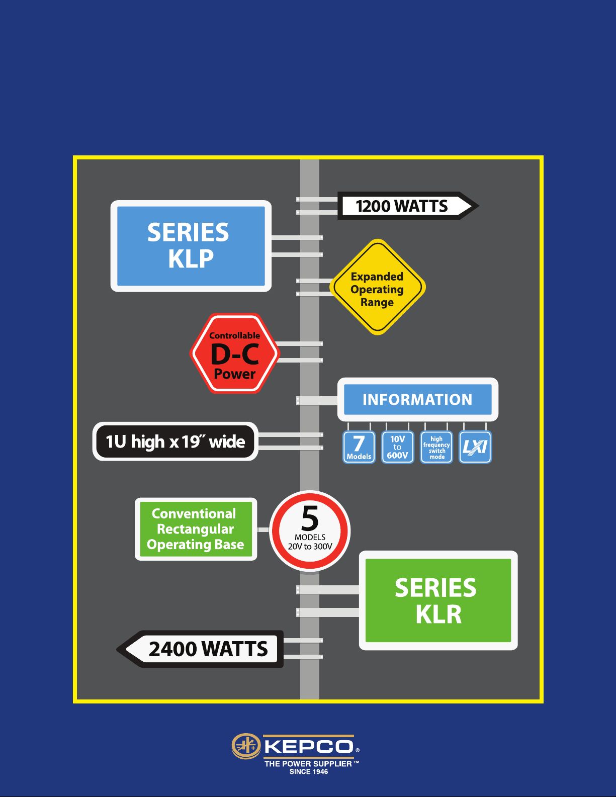
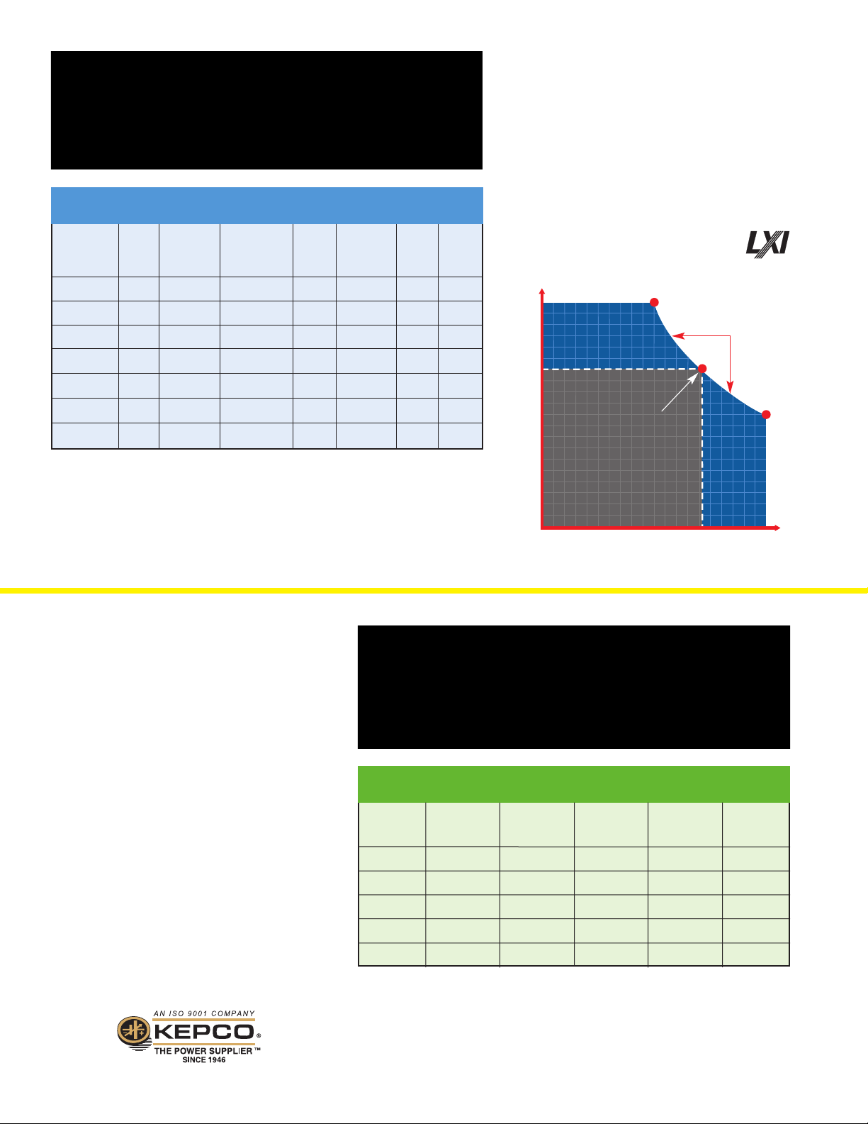
KEPCO SERIES KLP
Using high-frequency switch-mode topology for high
efficiency and small size, the KLP provides 1200 watts
of well-regulated, controllable d-c power in a 1U
(1.75 inch high) by 19 inch rack-mountable package.
KLP replaces the need for multiple power supplies
by expanding the operating region. The breakthrough
of a hyperbolic power limit delivers a full 1200 Watts
over an expanded operating range, not just the
conventional rectangular operating area.
www.kepcopower.com/klp.htm
V
75
ADDITIONAL
OPERATING
REGION
KEPCO KLP’S
1200 WATT
EXTENDED
MAXIMUM
POWER
RANGE
“A” THRU “C”
KLP 300-8
KLP 600-4
(1) The maximum current and voltage are constrained by the 1200 watt power limitation.
(2) Bandwidth: 20MHz; low frequency ripple may be higher at loads less than 30 Watts.
(3) Standard models (no suffix) include built-in GPIB and RS-232 interfaces.
E-series models (Suffix E) include built-in GPIB and LAN interfaces.
0-300V
0-600V
4A@300V
2A@600V
0.1A
0.05A
0-8A
0-4A
150V@8A
300V@4A
150 mV
150 mV
KEPCO SERIES KLR
Kepco introduces Series KLR, offering 2400 Watts
of stable, controllable d-c power in the industry
standard 1U package. Five models from 20 Volts to
300 Volts are available with a conventional rectangular
operating area. Input is 180-264V a-c, single phase.
GPIB, RS232 and isolated analog programming are
all standard.
www.kepcopower.com/klr.htm
KLR MODEL TABLE
(1)
MODEL
KLR 20-120
KLR 40-60
KLR 75-32
KLR 150-16
KLR 300-8
87%
88%
RATED
VOLTAGE
RANGE
0-20V
0-40V
0-75V
0-150V
0-300V
36
VOLTS
0
MINIMUM
PROGRAMMABLE
CURRENT
1.5A
0.8A
0.4A
0.2A
0.1A
CONVENTIONAL
POWER SUPPLY’S
MAXIMUM
POWER POINT
CONVENTIONAL
OPERATING REGION
16
AMPER ES
RATED
CURRENT
RANGE
0-120A
0-60A
0-32A
0-16A
0-8A
RIPPLE AND
(2)
NOISE
p-p
100 mV
80 mV
80 mV
100 mV
150 mV
ADDITIONAL
OPERATING
REGION
33
EFFICIENCY
@
230V a-c
87%
88%
87%
88%
89%
I
(1) Standard models (no suffix) include built-in GPIB and RS-232 interfaces.
E-series models (Suffix E) include built-in GPIB and LAN interfaces.
(2) Bandwidth: 20MHz; low frequency ripple may be higher at loads less than 30 Watts.
KEPCO, INC. • 131-38 Sanford Avenue • Flushing, NY 11355 USA • Tel: (718) 461-7000 • Fax: (718) 767-1102
Email: hq@kepcopower.com • www.kepcopower.com
Data subject to change without notice.
© 2013 KEPCO, INC. Litho in USA
Page 3

FEATURES
MARKETS AND APPLICATIONS
KLP: Provides 1200W output power over a hyperbolic output power envelope,
resulting in full output power availability over the range of 8V, 150A to 600V, 2A
KLR: Provides up to 2400W output power via a conventional rectangular output
power envelope, resulting in full output power at model limits only
Switch mode topology for cool, efficient operation
GPIB and isolated analog programming included on all models
Standard models have an RS-232 interface
E-Series models replace the RS-232 interface with an Ethernet (RJ-45) connector
supporting LAN (LXI certified for KLP)
KLP: 1U panel height at 1200 watts
KLR: 1U panel height at 2400 watts
Front to back air flow allows full power operation without spacers between supplies
KLP: Operates over universal a-c mains voltage range of 90 - 264V a-c with PFC
KLR: Operates over a-c mains voltage range of 180 - 264V a-c with PFC
KLP: Stud-style output power terminals for LV models (10V, 20V, 36V), and
Euroblock output power terminals for HV models (75V, 150V, 300V, 600V)
KLR: Stud-style output power terminals for LV models (20V, 40V), and
Euroblock output power terminals for HV models (75V, 150V, 300V)
• Aerospace and Satellite Test
• Telecom and IT Industry
• Automated Test Equipment
• Factory Automation
• QC Testing
• Burn-in
• Solar
• Water Purification
• Thermal Process Control
• Chemical Processing
• Semiconductor Manufacturing
• Battery Charging and Testing
• Electroplating, Sputtering and Coating
• New Energy R&D
KLP/KLR INPUT SPECIFICATIONS
SPECIFICATION RATING/DESCRIPTION CONDITION
SERIES KLP SERIES KLR
a-c Voltage Nominal 100-240V a-c 200-240V a-c Single phase
Range 90-265V a-c 180-265V a-c Wide range
Input Nominal Range 50-60 Hz 50-60 Hz
Frequency
Power Factor (PF) Typical 0.99 0.99 Meets EN 61000-3-2
Maximum 120V a-c 13A rms N/A Rated load (1200W)
Input Current
Inrush Current 265V a-c 40A 40A Peak
Input Fusing Circuit breaker Circuit breaker 2-line
Low a-c Protection 87V a-c self protected 175V a-c self protected User-selectable recovery
Output Holdup Typical 10 milliseconds 5 milliseconds Ride through
Leakage 115V a-c, 60 Hz 1.2mA max N/A
Current
(1) Either PROTECTED (output disabled and locked until source power recycled) or SAFE (output disabled with unit programmed to last setting; power recycling
not needed for recovery) or AUTO (when fault clears, unit automatically recovers to programming setpoints and output state (enabled/disabled) as before fault
was detected.
NOTE: Contact Kepco Applications Engineering for d-c input.
Maximum 45-440 Hz 45-440 Hz Increased leakage above 66 Hz
240V a-c 6.5A rms N/A Rated load (1200W)
230V a-c N/A 12A rms Rated load (2400W)
132V a-c 20A N/A Peak
(1)
230V a-c, 50 Hz 2.3mA max 2.3mA max
KEPCO, INC. • 131-38 Sanford Avenue • Flushing, NY 11355 USA • Tel: (718) 461-7000 • Fax: (718) 767-1102
Email: hq@kepcopower.com • www.kepcopower.com
Page 4

KLP/KLR OUTPUT CHARACTERISTICS
KLP/KLR GENERAL SPECIFICATIONS
SPECIFICATION RATING/DESCRIPTION CONDITION
Stabilizer Type
Adjustment
Range
Source Effect
Load Effect
Temperature
Effect
Time Effect
(drift)
Error Sensing
Isolation
Voltage
Transient
Recovery
for Load
Change
Turnon/turnoff
Overshoot
Rise Time
Voltage
Current
Voltage
Current
Voltage
Current
Voltage
Current
Voltage
Current
Excursion
Recovery
Voltage
min-100% of rated current
75-600V: 600V d-c or peak
CV/CC Voltage/Current
0-100% of rated voltage
(1)
0.01% E
max
0.01% l
max
0.02% E
max
0.05% l
max
0.01%/ºC
0.01%/ºC
0.02%/24hr
0.02%/24hr
0.25 volts per wire
10-40V: 100V d-c or peak
1% of E
max
2 msec 10% min load, Return
2% max
Rated output, any load
10 -40V: 30 msec
75V: 40 msec
150V: 50 msec
300V: 60 msec
No minimum
load required
Over full
source range
Over full
rated load
0-50ºC
After 30 minute
warmup
Above rated output
Either output
terminal to ground
50% load step 2A/
microsecond max
to 0.1% of setting
0-E
max
rated load
(resistive)
600V: 75 msec
Current
10 -40V: 30 msec
75V: 40 msec
150V: 50 msec
300V: 60 msec
0-I
max
rated load
(resistive)
600V: 75 msec
Fall Time
Voltage
No Load
(2)
10V: 475 msec
20V: 525 msec
36V: 825 msec
-0, no load
E
max
(open circuit)
40V: 975 msec
75V: 2820 msec
150V: 4850 msec
300V: 4400 msec
600V: 3150 msec
Voltage
Rated Load
10 -40V: 30 msec
75V: 40 msec
150V: 50 msec
300V: 60 msec
-0
E
max
rated load
(resistive)
600V: 75 msec
Current
10 -40V: 30 msec
75V: 40 msec
150V: 50 msec
300V: 60 msec
-0
I
max
rated load
(resistive)
600V: 75 msec
Overvoltage
Protection
Overcurrent
Protection
Output Load
Wire Protection
Parallel Operation
Programmable
20-120% of E
max
Programmable
72-120% of I
max
Shutdown
Active load sharing within
5% of I
0
rated
User selectable
User selectable
User selectable
(3)
recovery
(3)
recovery
(3)
recovery
Up to 5 units
maximum
(4)
(1) See Model Table for minimum programmable current.
(2) For improved fall time performance consult factory for "R" (Rapid Output
Discharge) option.
(3) Either PROTECTED (output disabled and locked until source power
recycled) or SAFE (output disabled with unit programmed to last setting;
power recycling not needed for recovery).
(4) E-series are not Master/Slave capable.
KEPCO, INC. • 131-38 Sanford Avenue • Flushing, NY 11355 USA
Tel: (718) 461-7000 • Fax: (718) 767-1102
Email: hq@kepcopower.com • www.kepcopower.com
SPECIFICATION RATING/DESCRIPTION CONDITION
Temperature Operating -10 to +50°C Rated load
+50 to +70°C Derate current 3%
per °C over 50°C
Storage -40 to +85°C
Cooling 3 internal d-c fans Exhaust to the rear
Humidity 10 to 90% RH Non-condensing
Shock 20g, 11msec ± 50% Non-operating
half sine
Vibration 5-10Hz 10mm double amplitude 3-axes, non-operating
10-55 Hz 2g 3-axes, non-operating
Altitude sea level to 10,000 ft. 0-3,000 ft: 100%,
linear derating
to 70% of power
at 10,000 ft.
Loss of Shutdown User selectable
Source Power recovery
Overtemperature Shutdown User selectable
Protection recovery
(1)
(1)
Fan Failure Shutdown Recovery requires
power recycling
Withstand Input- 2121V d-c 25°C, 65% RH
Voltage Chassis (all models)
Output- 1250V d-c
Chassis (10V-40V models)
2121V d-c
(75V-600V models)
Input- 2500V d-c
Output (10V-40V models)
4242V d-c
(75V-600V models)
(1) Either PROTECTED (output disabled and locked until source power
recycled) or SAFE (output disabled with unit programmed to last setting;
power recycling not needed for recovery) or AUTO (when fault clears,
unit automatically recovers to programming setpoints and output state
(enabled/disabled) as before fault was detected.
KLP/KLR PHYSICAL SPECIFICATIONS
SPECIFICATION RATING/DESCRIPTION CONDITION
Weight English 15 lbs Shipping: 20 lbs
Metric 6.82 Kg Shipping: 9.07 Kg
Dimensions English 19" x 1.735" x 17.5" Depth excluding
W x H x D
Metric 482.6mm x 44.45mm
x 443.7mm
Source Power IEC 320-C19 250V a-c,
Connector appliance inlet 16A (VDE)
Load 10-40V Nickel-plated copper Provision for
Connections models busbar with integral safety covers
threaded stud
(1/4-20-1/2in.)
75-600V Shock-safe Euroblock,
models single conductor size:
20-10 AWG
(0,5-5,0 mm
Analog 15 pin D-sub
Programming Port
Digital Primary Standard GPIB IEEE 488.2 (GPIB)
Programming connector
Ports
Secondary 9 pin D-sub RS 232 (standard
Secondary RJ45 LAN (E-Series
Feedback/ 5 position low profile
Control Input Euroblocks
2
)
connectors and
terminal blocks
125V a-c,
20A (UL)
models only)
models only)
Page 5

KLP/KLR PROGRAMMING CHARACTERISTICS - LOCAL
SPECIFICATION RATING/DESCRIPTION CONDITION
Local Control Rotary encoders Panel mounted
Local Control Coarse ~100 LSB/step Depress control for fine resolution
Resolution
Setting Range 0-100% of rating KLP will automatically adjust limit to maintain 1200W maximum
Power Up Voltage Defaults to zero Last setpoint values may be saved for voltage and current
Protection Overvoltage 20-120% of E
Fine 1 LSB/step
Current Defaults to min value
Overcurrent 72-120% of I
max
max
prior to unit shutdown, and recall them when unit is next turned onSettings
Programmable; accessed via front panel
protect switch or SCPI command over digital bus Limits
KLP/KLR PROGRAMMING CHARACTERISTICS - DIGITAL
SPECIFICATION RATING/DESCRIPTION CONDITION
Supported Standard GPIB and RS 232 Supports SCPI command set for
Interfaces Models GPIB and RS 232
E-Series GPIB and LAN Support SCPI command set for
Models Support four interfaces for LAN: GPIB and LAN
GPIB GPIB address range: 1 to 30 Factory default is 6
RS 232 Standard Baud rate range: 2400, 4800, Factory default is 38,400
Digital Remote Isolation Safety Extra Low Voltage (SELV)
Control
Programming Resolution 0.024% of E
Programming Accuracy 0.05% of E
Readback Resolution 0.024% of E
Readback Accuracy 0.1% of E
Status Reporting OVP, OCP, OTP, Output Lead Fault (OLF),
Models Only 9600, 19,200 or 38,400
Format Compatible with SCPI protocols W98 SE and later operating systems
Web interface, port 80
SCPI Telnet, port 5024
SCPI Sockets, port 5025
VXI 11, port 1024
and I
max
max
max
max
fan failure, source power loss
and I
and I
and I
max
max
max
max
KLP/KLR PROGRAMMING CHARACTERISTICS - ANALOG
SPECIFICATION RATING/DESCRIPTION CONDITION
Analog Remote Selection Activate with jumper at analog Recognized during power up
Control programming connector
Isolation Safety Extra Low Voltage (SELV)
Analog Input 2Hz (0.5 Second) applies to programming by Analog input voltage digitized (12-bit resolution), optically
Update Rate voltage/resistance and readback specifications isolated, then processed by digital section
Programming Voltage 0-10V Voltage equivalent to Full Scale
By Voltage can be reduced by the user
Current 0-10V See Model Table for minimum programmable current.
Programming Voltage 0-10K ohms Resistance equivalent to Full Scale
By Resistance can be reduced by the user
Current 0-10K ohms See Model Table for minimum programmable current.
Readback 0-10V proportional signal Propor tional to analog control voltage/resistance
Remote inhibit TTL compatible Dual polarity, can be active (inhibit
Composite Status Flag Isolated form C contacts Programmable. Flags system fault.
Voltage equivalent to Full Scale can be reduced by the user
Resistance equivalent to Full Scale can be reduced by the user
the output) for either a TTL high or low
Additional user selectable flag: a) transition from CV to CC mode
or b) transition from CC to CV mode.
Page 6

The Rapid Output Discharge Circuit (RODC) option (suffix R) is available on
RODC
Rapid
Output
Discharge
Circuit
Option
all KLP/KLR models. This circuit rapidly discharges the output capacitance,
thus significantly reducing response time to reductions in output voltage.
The circuit consists of a voltage detector that compares the programmed
and actual values of output voltage. The discharge circuit is activated only
when the actual voltage exceeds the programmed value.
Without the RODC circuit, discharge of the total output capacitance
(internal and external) is achieved through a combination of the external
load resistance and an internal current sink. For high load resistance or
open circuit conditions at the output, response time (fall time) can vary
from hundreds of milliseconds to seconds depending upon the magnitude
of the high-to-low voltage transition.
With the RODC option, output fall time is reduced to approximately the
same value as rise time, even with external capacitance equal to 50%
of the nominal internal output capacitance.
Please see the website for details about this option.
Visit www.kepcopower.com/klp.htm and
www.kepcopower.com/klr.htm for more information
Looking For More High Power, Low Prole Power Supplies?
SERIES KLN
The Kepco Series KLN is a new family of automatic
crossover, low-profile, high-performance, low-cost
programmable power supplies. The KLN Series offers
stable d-c power in a 1U high, half-rack package for
750W, a 1U high, full-rack package for 1500W and
a 2U high, full-rack package for 3000W. A total of
39 voltage-current combinations are offered. Output
voltages range from 0-6 Volts to 0-600 Volts and
output currents range from 0-400 Amps down to
0-1.25 Amps. Speed-controlled fans limit acoustic
noise for bench-top applications when full power is
not needed.
Precise programming of voltage, current and their
limits may be achieved from the front panel, or by
analog means or by RS 485 digital control. GPIB
or LAN interfaces are factory-installed options.
750W 1U, Half-Rack (top), 1500W 1U, Full Rack (middle), 3000W 2U, Full Rack (bottom)
KLN Series Programmable Power Supply:
For more information visit
www.kepcopower.com/kln.htm
KEPCO, INC. • 131-38 Sanford Avenue • Flushing, NY 11355 USA • Tel: (718) 461-7000 • Fax: (718) 767-1102
Email: hq@kepcopower.com • www.kepcopower.com
 Loading...