

Page 1

Internet
/
http://www.kikusui.co.jp
Electrostatic Discharge Simulator
KES4021A/4022A
NEW
Electrostatic Discharge Simulator
KES4021A/4022A
Complies with the EN/IEC61000-4-2 standard
Maximum testing voltage of ±30 kV exceeds required test levels.
Easy-to-use panel design
Equipped with the programming feature(KES4022A)
Applied to various standards of the electrostatic testing
Page 2
Compliant with the IEC61000-4-2 Ed2.0:2008 Standard
KES
KES
4024024021A111A1A
4
40
1A
FOR
IS
ISOTD.TED2
E
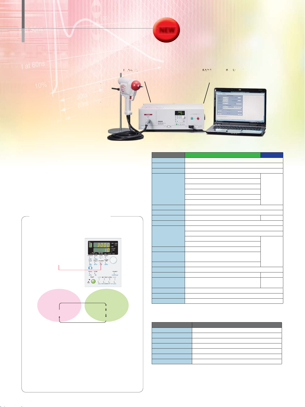
Electrostatic Discharge Simulator
NEW
KES4021A/4022A
IEC61000-4-2 Ed2.0:2008 / ISO10605 Ed2.0:2008
IEC61000-4-2 Ed2.0: 2008 Complied
An electrostatic discharge is a common phenomenon. The electric shock by the electrost atic
discharge occurs such as when touching the door
knob, walking o n the ca r pe t in dry co nditi on, or ge tting on and off from the aut omobile. When the ark
current or the elec tromagnetic wave were gener-
・
to the standard
[Applied to the automated test operation]
KES4022A
■
[For the manual operation]
KES4021A
■
ated by those electrostatic discharge fl ows into the
electric circuit, it may cause a signifi cant adverse effect such as malfunction of the electronic device or
destruction of the electric circuit. These issues are
deeply concerned under the present circumstances
because of the semiconductors have been widely
adopted and used in the most electric devices or
electronics equipments. Therefore, the related standard of the electrostatic discharge immunity test has
become established. We offer the product which
complies to the standard of the immunity test that
can simulate the direct or indirect discharge to the
electrical device a nd the electronic equipment from
the charged human body.
[Features]
X
Electrostatic discharge simulator compliant with
EN/IEC 61000-4-2
X
Maximum test voltage of ±30 kV is more
than suffi cient for required testing levels
X
Applied to the ISO 10605 Ed2.0:2008 standard
*The ISO10605 Ed2.0 stipulates the combination of the capacitor with an
accumulated energy (150pF/330pF) and the discharge resistor (330
applied to the edition of IEC61000-4-2 Ed2.0:2008/ISO10605 Ed2.0:2008 includes
the optional CR unit (CR32-KES, CR33-KES, CR34-KES) and the discharge tip
(AT32-KES, CT32-KES, ST31-KES, ST32-KES) besides the standard accessory of
the CR unit (CR31-KES) and the discharge tip (AT31-KES, CT31-KES).
* If the optional standard ISO10605 Ed2.0:2008 is purchased at later date, the extra
cost will be charged for the calibration combined with main unit.
Exclusive features of the KES4022A
Test condition settings, the programming feature
X
by the main unit or using the application software
Selective 4 test modes depending on the application
X
4 operation modes
(Manual, IEC test
level, step, sequence)
can be selected by the
OPERATION key
Display area
Manual operation
Tests using the specified
test conditions
single operation
OPERATION key
Manual operation (single operation)
●
When the test is performed, the test conditions remain the same unless you change the
conditions.You can also select the IEC61000-4-2 test level.
IEC test level operation
●
Auto operation that you set for the IEC test levels and polarities.
Testing is performed in order from the lowest IEC61000-4-2 test level to the selected test
level.
Step operation
●
Auto operation that you set for the step voltage and polarities.
Testing is performed in sequence according to the set starting, ending, and step voltage.
Sequence operation
●
Auto operation that you set for arbitrary test conditions.
Testing is performed in sequence from step when the number of test conditions were set.
Auto operation
Test consisting of
several test condition combinations
IEC test level operation
step operation
sequence operation
2
Ω
/2kΩ). The unit
Make the setting of
complex test condition easier !
Equipped with the
convenient program feature !
(KES4022A)
Model KES4022A. The gun stand is option. PC is not included.
[Specifications of the main unit]
Item KES4022A KES4021A
Discharge method Contact discharge and Air discharge
Set voltage 0.00kV to 30.5kV(Guaranteed specifi cations: 0.50kV to 30.0kV)
Polarity Positive and Negative
*
Polarity setting
Charge resistor 50MΩ (combined with the discharge gun)
Discharge interval 0.05 / 0.1s to 99.9s
Discharge cycle
Trigger Main panel trigger and Discharge gun trigger
Type of test
Discharge points 1 point to 10 points
Memory operation
Wait feature ON or OFF
Discharge Current Waveform
Interface RS232C interface, External connection I/F (Option)
Application Software CD-ROM
Power supply AC100V to 240V 50/60Hz
Dimensions 430W×132H×370Dmm
Weight
The KES4021A applies only for the setting level
*
*Up to 20 steps of confi guration with different test conditions in a single sequence test.
[Specifi cations of the discharge gun]
Item Common specifi cations for KES4021A / KES4022A
Output voltage 0.00kV to 30.5kV
Energy storage capacitor 150pF±10%(replaceable)*
Discharge resistor 330
Charge resistor 50M
Dimensions 218W(excluding the discharge chip)×232.5H×63Dmm
Weight Approx.1.5Kg(including the 2.5 m high voltage cable)
Discharge chip Air discharge tip(AT31-KES), Contact discharge tip(CT31-KES)
*The IEC61000-4-2 stipulates the combination of the energy storage capacitor (150pF) and the discharge resistor
(330Ω). The CR unit (CR31-KES), included as a standard accessory, is the type of fi xed component value. For
other combinations, the optional combination with different component values are available.
[Accessories]
•
Power cord:1 pc., • CR unit[CR31-KES], • Air discharge tip[AT31-KES]:1 pc, • Contact discharge
tip[CT31-KES]:1 pc, • CD-ROM:1 pc.(KES4022A), • Operation Manual:1 copy
・
Complied to the standard
[Applied to the automated test operation]
KES4022A FOR ISO.STD.ED2
■
[For the manual operation]
KES4021A FOR ISO.STD.ED2
■
PoS: for the positive polarity only
nEG:for the negative polarity only
P-n: Start with a positive voltage and switch the polarity for each step
n-P: Start with a negative voltage and switch the polarity for each step
PA-nA: Test all positive steps then all negative steps
nA-PA: Test all negative steps then all positive steps
step operation: in step voltage 0.01 to 30.0kV
Stores 20 sets of testing conditions
for each operation (a total of 80 sets)
IEC61000-4-2 Ed2.0: 2008, ISO10605 Ed2.0: 2008
1 to 99999/Continuous
Manual operation
IEC test level operation:level 1,2,3,4*
sequence operation*
approx. 8.0kg(17.6 lb)
Ω
(with the main unit connected)
Ω
±10%(replaceable)*
–
1 to 999/Continuous
–
RS232C(Option)
–
Page 3

[Application Software]
The complex setting of test condition can be easily made by entering the specified parameters.
(Remarks) The execution or aborting the test can not be controlled remotely from the PC. This software can not be used for the KES4021A.
The KES4022A includes a dedicated application software as a standard accessory. The test conditions can be set
either from the front panel or through by the PC. Moreover, the specifi ed condition of the parameter can be easily
entered in the excel format as it activates as macro program.
System requirement
[
Interface : RS232C
●
OS : Windows XP Professional (SP2 or later, 32 bit version)
●
Application software : Microsoft Excel 2003 VBA
●
]
[Optional components]
●
Option parts for IEC61000-4-2 standard test
CR unit and discharge tip are available for the IEC61000-4-2 standard test.
Product name Model name
Ω
CR unit (150 pF/330
Air discharge tip(Resistance value 330
Contact discharge tip(Resistance value 330
●
Option parts for ISO 10605 standard test
CR unit and discharge tip are available for the ISO 10605 standard test.
CR unit(330pF/330)for ISO10605 Ed.2.0 CR32-KES
CR unit(150pF/2k)for ISO10605 Ed.2.0 CR33-KES
CR unit(330pF/2k)for ISO10605 Ed.2.0 CR34-KES
Air discharge tip(Resistance value 2k
Contact discharge tip(Resistance value 2kΩ) CT32-KES
Sphere discharge tip(Resistance value 330
Sphere discharge tip(Resistance value 2k
●
C Unit/Discharge Resistor*
IEC61000-4-2 specifies the combination of the energy storage capacitor
and the discharge resistor. Changing the combinations of the C unit and the
discharge resistor can simulate various conditions
*Some combinations of the energy storage capacitor and the discharge resisitor may
shorten the life of the discharge-generating high-voltage switch of the discharge gun.
[C Unit ]
This unit is inserted into a discharge gun. It consists of the energy storing capacitor.
The discharge resistor(sold separately) must be connected for the operation.
[Discharge Resistor]
Equipped inside the option C Unit to limit discharge current.
) for IEC61000-4-2 CR31-KES
Ω
) AT31-KES
Ω
) CT31-KES
Product name Model name
Ω
) AT32-KES
Ω
) ST31-KES
Ω
) ST32-KES
.
Capacity Model name
150pF EC21-KES
100pF EC22-KES
200pF EC23-KES
250pF EC24-KES
300pF EC25-KES
330pF EC26-KES
400pF EC27-KES
500pF EC28-KES
Resistance value Model name
Ω
330
100
150
200
300
400
500
1k
1.5k
2k
5k
10k
10
Ω
Ω
Ω
Ω
Ω
Ω
Ω
Ω
Ω
Ω
Ω
Ω
DR21-KES
DR22-KES
DR23-KES
DR24-KES
DR25-KES
DR26-KES
DR27-KES
DR28-KES
DR29-KES
DR30-KES
DR31-KES
DR32-KES
DR33-KES
●
Discharge Gun Stand
The stand used to hold the discharge gun. It is convenient for discharging
electricity at the same point (vertical joint plate in particular).
Product name Model name
Discharge gun stand GS21-KES
●
Testing Environment Fixtures
EC61000-4-2 specifies the testing environment based on equipment type.
Required equipments for performing the electrostatic discharge immunity test
applied to the EUT
[ For Desktop Equipments ]
Fixtures for the test desktop equipment such as a PC.
Product name Model name
Test table TT21-KES
Ground reference plane
Horizontal coupling plane ZC21-KES
Insulation sheet IS21-KES
Vertical coupling plane (table-top)
Resistor cable CL21-KES
*Optional resistance cable (model : CL21-KES) is required
*
*
GP21-KES
VC21-KES
[ For Floor-Standing Equipments ]
Fixtures for the test fl oor-standing equipment such as a rack mounted equipment.
Product name Model name
Ground reference plane GP21-KES
Vertical coupling plane (fl oor-standing)* VC22-KES
Insulating support IP21-KES
*Optional resistance cable (model : CL21-KES) is required
●
Waveform Measuring Instrument
The instrument used to measure the discharge current waveform defi ned in
IEC61000-4-2.
Product name Model name
Current target (For Ed2.0)
Target adapter line (For Ed2.0)
Coaxial cable for high frequency (SMA-SMA)
20dB Attenuator
Conversion Connector (SMA-BNC)
Made-to-order
production
3
Page 4

Electrostatic discharge immunity test
Outline of the IEC61000-4-2 Ed 2.0
This stand ard stipulates th e immunit y requirements and test meth ods for electrical and
electroni c equipment s ubjected to stat ic electrici ty discharg es, from ope rators directly,
and from personnel to adjac ent objects. It additionally d efines range s of test levels
which relates to different environmental and installation conditions and esta blishes test
procedures.
Test method
●
The contact discharge te sting is preferre d.
The air disc harge testing should be applied only whe n the contact d ischarge testing can
not be performed.
ESD test instruments
Specifi cation of the ESD generator
Energy storage capacitor
Discharge resistor 330
Output voltage Contact discharge 8kV and Air discharge 15kV
Tolerance of the output voltage display
Polarity of the output voltage Positive and Negative
Holding time At least 5 seconds
Discharge operation mode
Discharge current waveform Refer to the fi gure as shown on the right
●
Sample layout of the test instruments for the Table-top equipment
Put a 0.8 meter h igh test table (made of wo od) on the ground reference
•
plane, then plac e the horizontal coupling pla ne on the test tabl e.
Connect two 470k resistors between the horizontal coupling plane and
•
the ground reference plane as shown in the fi gure.
In the testing method of indirect discharge, it observes the effect of
•
EUT when discharging to the vertical or horizontal coupling plane.
Typical position of the discharge
to the vertical coupling panel.
Insulation sheet
Horizontal coupling
plane
1.6m×0.8m
Test table
0.8m
150pF
Ω
±5%
Single discharge (discharge interval must be at least 1 second)
Use a horizontal coupling plane (1.6m×0.8m) and a vertical coupling
•
plane (0.5m×0.5m)
Connect two 470k resistors between the vertical coupling plane and
•
the ground reference plane.
Distance between the horizontal coupling pane and the EUT
•
Place the EUT about 0.1m from the edge of the horizontal coupling plane.
•
Place the electrostatic discharge simulator on the ground reference
•
plane as close as possible.
Vertical coupling plane
0.5m×0.5m
0.1m(Distance between the vertical coupling panel and the EUT)
0.1m(Distance between the horizontal coupling panel and the EUT)
EUT
(Equipment Under Test)
Typical position of direct discharge
Typical position of the discharge
to the horizontal coupling panel.
ESD generator
The range of the preferred test level for the ESD testing
* X can be set at any level specifed by the manufacturer and the user.
The defi nition of the output current waveform of the ESD generator
To the commercial
Level Contact discharge Air discharge
1 2kV 2kV
2 4kV 4kV
3 6kV 8kV
4 8kV 15kV
X special special
Level
Indicated
voltage
1 2kV 7.5A 0.8ns 4A 2A
2 4kV 15A 0.8ns 8A 4A
3 6kV 22.5A 0.8ns 12A 6A
4 8kV 30A 0.8ns 16A 8A
First peak
current of
discharge
(±15%)Ip
●
Ipeak I
power source
Ground wire
Rise time tr with
discharge
switch(±25%)
Current (±30%)
at 30 ns
Typical waveform of the discharge
output current of the ESD generator
100%
90%
Iat30ns
Iat60ns
tr=0.8ns±25%
10%
30ns
60ns
tr
10%
I30
Current (±30%)
at 60 ns
I60
t(ns)
470k7 resistor(Resistance cable)
Ground reference plane
●
Sample layout of the test instruments for the Floor-standing equipment
Put a 0.1 meter high of insulation pallet on
•
the ground reference plate, then place the
EUT on it.
The Indirect discharge testing is the test
•
method to observe the effect to the EUT while
discharging to the vertical coupling plane.
Connect two 470k resistors between the
•
vertical coupling plane and the ground
reference plane.
Place the electrostatic discharge simulator
•
on the ground reference plane as close as
possible.
0.1m(Distance between the vertical coupling panel and the EUT)
Floor-standing vertical coupling panel
Vertical coupling plane:0.5m×0.5m
470k7 resistor(Resistance cable)
ESD generator
To the commercial
power source
Typical position of the discharge
to the vertical coupling panel.
Typical position of direct discharge
EUT
(Equipment Under Test)
Insulation pallet
Distributor:
●
0.05m
〜
0.15m
Ground reference plane
Ground wire
●
Simplified diagram of the ESD generator
DCHV
Supply
Cs+Cd: 150pF (typical value)
Cd: Distribution volume existed between the generator and
peripheral devices
Rd:3307 (typical value)
Cs+Cd
1-877-876-2807
1633 Bayshore Highway, Suite 331, Burlingame, CA 94010
Phone : 650-259-5900 Facsimile : 650-259-5904
Room, D-01,11F, Majesty Bld, No.138, Pudong Ave, Shanghai City
Phone : 021-5887-9067 Facsimile : 021-5887-9069
www.kikusuiamerica.com
www.kikusui.cn
All products contained in this catalogue are equipment and devices that are premised on use under the
■
supervision of qualified personnel, and are not designed or produced for home-use or use by general
consumers.
quality.
necessary.
respective registered trade name or trade mark.
catalogue may differ from actual products due to a limited fi delity in printing.
made to provide the information as accurate as possible for this catalogue, certain details have unavoidably
been omitted due to limitations in space.
appreciated if you would inform us. ■Please contact our distributors to confirm specifications, price,
accessories or anything that may be unclear when placing an order or concluding a purchasing agreement.
Specifi cations, design and so forth are subject to change without prior notice to improve the
■
Product names and prices are subject to change and production may be discontinued when
■
Product names, company names and brand names contained in this catalogue represent the
■
Colors, textures and so forth of photographs shown in this
■
If you fi nd any misprints or errors in this catalogue, it would be
■
Although every effort has been
■
Printed in Japan Issue:Apr.2010 201004pdf EC11
 Loading...