

Page 1
JT 5510 / JT 5550
JT 5510 TransienT generaTor
JT 5550 Load dump generaTor
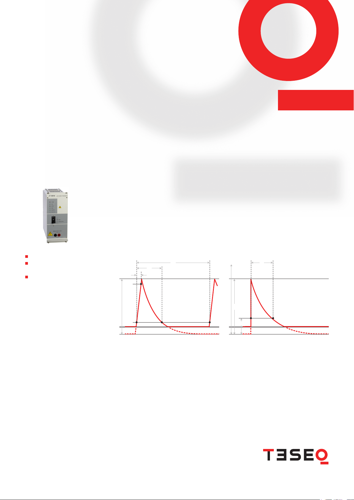
The JASO D001-94 from the Japanese Automotive Standards Organization departs from the traditional
ISO/SAE pulses in signicant ways. These pulses have a 1 µs rise time, use special output impedances,
methods of measuring pulse width, and pulse coupling. The JASO D001-94 forms the basis of other
Japanese standards. This is one of a series of Gemini JASO based modules that was developed for usage
with a NSG 5500 capacitive discharge immunity simulation system.
For many classic Japanese
immunity tests
Cost-effective addition to the
NSG 5500 automotive transient
generator
JT 5510 JT 5550 Plug-in modules for JASO D001-94
U
OV
t
t
d
t
r
90%
U
S
10%
A
1
2.3 ∙
τ = t
d
U
OV
V
V
P
36.8%
A
T
2.3 ∙ τ = t
d
These classic pulses are sometimes used as the base for other standards, Nissan for example. Therefore,
other pulses are also covered by this module.
Page 2

JT 5510 / JT 5550
JT 5510 TransienT generaTor
JT 5550 Load dump generaTor
Technical information JT 5510
Standard Versio n Year Pulse name Polarity Min
JASO D001-94 1994 Pulse A-2 positive 20 110 <1 5.75 2.5 0.4 1 120
JASO D001-94 1994 Pulse D-2 positive 20 17 0 <1 5 .75 2.5 0.9 1 120
JASO D001-94 1994 Pulse B-1 negative 20 80 <1 138,000 60,000 8 6 12 0
JASO D001-94 1994 Pulse B-2 negative 20 260 <1 4,6 00 2,000 80 6 120
JASO D001-94 1994 Pulse E negative 20 320 <1 60,000 26,000 210 30 120
Nissan 28400 NDS 3 1997 Pulse B-1 positive 20 80 <1 46,000 * * 3 120
Nissan 284 02 NDS 3 1997 Pulse B-2 negative 20 300 <1 7, 60 0 * * 3 120
Amplitude Pulse width Repetition rate
Max
[V]
tr
[V]
[µs]
[µs]
td
[µs]
Ri
t
Min
[Ω]
Max
[s]
[s]
Technical information JT 5550
Standard Versio n Year Pulse name Polarity Min
JASO D001-94 1994 Pulse A1 positive 50 110 <1 460 200 0.8 30 60
JASO D001-94 1994 Pulse D1 positive 50 120 <1 920 400 1.5 30 60
* Pulse width values typical - dened by pulse generation circuit, not by pulse characteristics
Note: The pulse shaping networks are designed internally with a 1 µs rise time. However, due to system capacitance of the
100 A coupler, typical rise times measured at the output of the system can be 3 µs or more.
Teseq AG
Nordstrasse 11F 45 42 Luter bach Swi tzerla nd
T + 41 32 681 40 40 F + 41 32 681 40 48
sales@tese q.com ww w.teseq.com
© Februa ry 2011 Teseq®
Specifications subject to change without notice.
®
Tes eq
is an ISO-registered company. Its products
are designed and manufactured under the strict
quality and environmental requirements of the ISO
9001. This document has been carefully checked.
However, Teseq
errors or inaccuracies.
®
does not assume any liability for
Amplitude Pulse width Repetition rate
Max
[V]
tr
[V]
[µs]
[µs]
td
[µs]
Ri
t
Min
[Ω]
Max
[s]
[s]
691-049A Februar y 2011
 Loading...