

Page 1
Acterna ANT-20SE
Advanced Network Tester ªSpeed Evolutionº± SONET
The test solution that sets
the pace in analyzing digital
communications systems
.
Multi-rate transmission
testing from DS1 to OC-192
.
Modular platform offering
SONET, DSn, SDH and ATM
capabilities
.
Built-in Pentium PC and
Windows 98 user interface for
easy processing of test results
.
Complemented by a lot of
easy-access, automated test
features
.
Large, color touchscreen plus
graphical results presentation
.
Prepared for OC-192 upgrade
As digital communications networks expand, the number of network operators is
growing too, and not just due to providers
merging across boarders. Different networks such as Cellular, CATV and Internet
are converging too. Nowadays, customers
demand next-to-perfect network availability, and a top-level transmission quality
has become a given.
ANT-20SE: A design
future-proofed for success
Powerful, precise test capability or simple
operation? PDH, SDH, SONET with all bit
rates from 1.5 Mbit/s to 10 Gbit/s, or ATM?
Don't worry about alternatives! You dont't
have to choose. ANT-20SE delivers sophisticated, precision testing that is easy to use
even in the most demanding environment
for all the above bit rates and for ATM.
In addition comprehensive jitter/wander
measurements up to OC-48 in complete
compliance with the ITU-T Rec. O.172 for
comparable, insightful and accurate measurement results.
The remote operation facilities, gives you
the opportunity to reduce your costs e.g.
operating the instrument from any windows
PC via modem or Ethernet LAN. Always
ready for new standards, higher bit rates
and the intelligent system components of
the future the ANT-20SE is at the forefront
of network installation and manufacturing
applications. Now with the ANT-10Gig a
subset of the ANT-20SE, it is taking you
one step further allowing the analysis of
OC-192/STM-64 signal structures.
One outstanding feature of the ANT-20
test solution has always been its ease of
thanks to the very large display and
use,
graphical
user interface based on Windows
98. The new ANT-20SE is even better since
the size and brightness of the display have
been further improved. The high speed
access buttons are another useful detail,
allowing you to rapidly launch commonly
occurring measurements.
Edition: May 2001
Page 2

Configuration Guide ANT-20SE
SONET
page 3±8
Optic
page 9±12
ANT-20SE ± SONET ± Mainframe BN 3060/02
Extended SONET testing BN 3060/90.02
Add SDH BN 3060/90.04
Drop & Insert/Through mode BN 3060/90.10
M13 Mux/Demux BN 3060/90.12
Mux/Demux 64k/140M BN 3060/90.11
Add BERT SDH BN 3060/90.33
OC-1/3, 1310 nm BN 3060/91.01
OC-1/3, 1310/1550 nm BN 3060/91.02
OC-1/3/12, 1310 nm BN 3060/91.11
OC-1/3/12, 1310/1550 nm BN 3060/91.12
OC-1/3/12/48*, 1310 nm +concatenated BN 3060/90.55
OC-1/3/12/48*, 1550 nm +concatenated BN 3060/90.56
OC-1/3/12/48*, 1310/1550 nm + concatenated BN 3060/90.57
&
&
&
&
&
&
&
&
&
&
&
&
&
&
CONC
page 10 ±12
Jitter
page 13±18
ATM
page 19±24
OC-1/3/12, 1310 nm +OC-48, 1550 nm + concatenated BN 3060/90.58
OC-12c BERT BN 3060/90.90
OC-12c ATM BN 3060/90.91
OC-12c virtual concatenation BN 3060/90.92
OC-48c BERT BN 3060/90.93
Jitter/Wander up to 155 Mbit/s BN 3060/91.30
Jitter/Wander up to 622 Mbit/s BN 3060/91.31
Jitter/Wander up to 2.5 Gbit/s BN 3060/91.32
Jitter/Wander at only 2.5 Gbit/s BN 3060/91.33
Jitter at only 2.5 Gbit/s BN 3060/91.34
ATM Basic BN 3060/90.50
ATM Comprehensive (PVC + SVC) BN 3060/90.51
Add ATM SONET BN 3060/90.53
&
&
&
&
&
&
&
&
&
&
&
&
&
2
AUTO ±
Remote
page 25±26
Add ATM SDH BN 3060/90.52
Automatic Test Sequencer CATS BASIC BN 3035/95.90
Automatic Test Sequencer CATS PROFESSIONAL BN 3035/95.95
* For OC-48 only see chapter optical interface
&
&
&
Page 3
Specifications ANT-20SE SONET
ANT-20SE Mainframe BN 3060/02
Includes:
.
Generator and analyzer for electrical STS-1 and STS-3 signals
allowing:
± Simulation and evaluation in the TOH / POH
± Generation and analysis of Anomalies and Defects
± Pointer generator and analyzer
.
Generator and analyzer for bit error rate tests (BERT) at
6 Mbit/s with unframed, 1.5 and 45 Mbit/s with framed and
unframed test patterns
.
VT1.5 mapping (DS1 in STS-1)
.
Touchscreen
.
4 extension slots
.
Ethernet and USB Interface
Generator unit
Digital outputs
Interfaces to Telcordia GR-253, TR-TSY-000499, ANSI T1.102
75 O coaxial output, adapter jack selectable from Versacon 9 adapter
system
Bit rates and line codes
DS1.............................. 1544 kbit/s; B8ZS, AMI, CMI
DS2................................... 6312 kbit/s; B8ZS, CMI
DS3..................................44736kbit/s; B3ZS, CMI
STS-1 . ...............................51840kbit/s; B3ZS, CMI
STS-3 . ................................... 155520kbit/s; CMI
100 O balanced output, Bantam jack
Bit rate and line codes
DS1.............................. 1544 kbit/s; B8ZS, AMI, CMI
Output pulses
DS1....................................... DSX-1 compatible
DS2............................................. rectangular
DS3, STS-1 ............................... HIGH,LOW,DSX-3
Bit rate offset. .....................................+500 ppm
Step size ......................................... 0.001 ppm
Clock
Internal clock generation
at all of the bit rates listed above.
Clock stability ......................................+2 ppm
Synchronisation to external signals
via 100 O balanced input, Bantam jack:
±
Reference clock . . . . . . . . . . . . . . . . . . . 1544 kHz and 2048 kHz
±
1544 kbit/s (B8ZS), 2048 kbit/s (HDB3) or
±
Receive signal
Clock outputs
±
Clock output at frequency of generator signal, approx. 400 mV
(when terminated into 75 O), BNC jack.
STS-3 output signal
Generation of a STS-3 signal conforming to Telcordia GR-253,
ANSI T1.105
The STS-3 signal consists of one internal STS-1 tributary signal with
the remaining two tributaries filled with UNEQ.
STS-1 output signal
Generation of a STS-1 signal conforming to Telcordia GR-253,
ANSI T1.105a
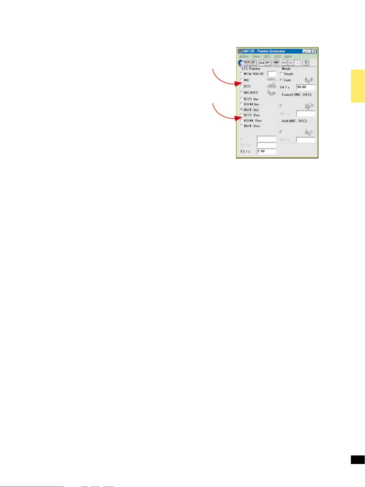
Manual
pointer
manipulation
or using
pre-defined
standard
sequences
Figure 1:
Pointer actions.
Mappings
VT1.5 mapping is included in the basic instrument. Other mappings
are added with option ªExtended SONET testingº.
Content of the selected tributary:
±
Framed or unframed DS1 or DS3 test pattern
±
M13 multiplex signal (with M13 MUX/DEMUX option)
±
External DS1 or DS3 signal (with D&I option)
±
Test pattern without stuffing bits (bulk signal to O.181)
Content of non-selected tributaries ............. framed PRBS 2
The various mappings are described along with the options.
11
±1
Generation of Pointer actions (figure 1)
Generation of pointer actions at the STS-1 and VT levels
simultaneously.
±
Pointer sequences to T1.105.03 with programmable spacing
±
Pointer increment/decrement (continuously repeated)
±
Single pointer
±
Pointer value setting with or without NDF
Contents of TOH and POH bytes
The content of all bytes with the exception of B1/B2/B3 and H1 to H4
is programmable with any byte or a user defined bytesequence p in m in n (p frames in m frames and the entire sequence
repeated n times) can be inserted.
Bytes E1, E2, F1, F2, and byte groups D1 to D3 and D4 to D12:
±
Transmission of a PRBS test pattern with bit error insertion
(see test patterns)
±
Insertion of an external data signal via V.11 interface (also for K1
and K2)
Trace identifier
J0,J1,J2 ..........programmable 16 byte ASCII sequence with CRC
J1, J2, additionally ...........programmable 64 byte ASCII sequence
H4 byte .................................4or48bytesequence
Error insertion
Error types .............................B1,B2,B3parity errors,
Triggering
Single error or error ratio ................... 2610
for B1, B3, REI-P . . . ..................... 2610±4to 1610
for bit errors . ............................ 1610±2to 1610
Step size for mantissa and exponent ........................... 1
Burst error: m anomalies in n periods
For FAS, B1, B2, B3, REI-L, REI-P ..............m=1to4.86610
frame alignment signal errors, REI-L,
REI-P, bit errors in test pattern,
code errors (single errors)
±3
to 1610
and n = 2 to 8001 frames or 0.2 s to 600 s
±10
±10
±9
6
3
Page 4

Alarm generation, dynamic
Alarm types .................... LOS,LOF,AIS-L, RDI-L, LOP-P,
AIS-P, UNEQ-P, PLM-P, RDI-P, RDIEPP,
RDIEPS, RDIEPC, PDI-P
Input levels
DS1....................................... DSX-1 compatible
DS3, STS-1 ............................... HIGH,LOW,DSX-3
Clock recovery pulling range .........................+500 ppm
m alarms in n frames . . ................ m=1ton±1,n
or
t1 alarm active,
t2 alarm passive .....................t1=0to60s,t2=0to600s
max
= 8000
Alarm generation, static (on/off)
Alarm types .................... LOS,LOF,AIS-L, TIM-L, RDI-L,
LOP-P, AIS-P, UNEQ-P, PLM-P, TIM-P,
RDI-P, RDIEPP, RDIEPS, RDIEPC, PDI-P
DS1, DS2 and DS3 output signals
Signal structures
±
Unframed test pattern
±
Framed test pattern (only DS1, DS3)
DS1 frame structure . . ................................ SF,ESF
DS3 frame structure . . . ...........................M13,Cparity
Error insertion
Bit errors in test pattern ....................error rate, single error
BPV............................................. single error
DS1Fbit(LOF).................. single error, 2 in 4, 2 in 5, 2 in 6
CRC-6 (ESF) ............................ single error, error rate
DS3Fbit(LOF)........... single error, 2 in 2, 2 in 3, 3 in 3, 3 in 15,
P parity, CP parity, FEBE ................... single error, error rate
Error rate .................................1610
Alarm insertion
DS1...................................... LOF,AIS, YELLOW
DS3........................... LOF,AIS, YELLOW, IDLE, FEAC
FEAC Far-End Alarm and Control Signals
To test that FEAC alarm and status information is correctly
transmitted, the relevant signal codes can be selected and inserted into
the DS3 C-bit frame format.
Test patterns
Pseudo-random bit sequences
11
PRBS: 2
2
Programmable word
Length .............................................. 16bits
±1, 215±1, 220±1, QRSS 20, 211±1 inv., 215±1 inv., 220±1 inv.,
23
±1 inv.
3in16,3in17
±2
to 2610
±9
Selectable input gain, CMI coded ..................... 15to23dB
B3ZS, B8ZS, HDB3, AMI coded ...................... 15to26dB
Selectable adaptive equalizers for DS3, STS-1 .................450ft
Monitor input for STS-3 and STS-12 NRZ signals
See chapter Optical Interfaces for details.
DS1 .....................1310 ft
STS-3 receive signal
(for signal structure, see under generator unit)
The ANT-20 demultiplexes one selectable STS-1 tributary from STS-3
and feeds it to the internal processor for evaluation.
STS-1, DS1 and DS3 receive signals
Signal structures as for generator unit
Trigger output
75 O BNC connector, HCMOS signal level
Pulse output for received bit errors, transmit frame trigger, transmit
pattern trigger or 2048 kHz reference clock
Included mapping
VT1.5 and STM-0 mapping
DS1 in STS-1 and 1.5 Mbit/s in STM-0
Modes ................ asynchronous, byte synchronous (floating)
Error insertion and measurement
Additional error types . ........................... BIP-V,REI-V
Alarm generation, dynamic
Alarm types................ LOP-V,AIS-V, LOM, UNEQ-V, RDI-V,
m alarms in n frames . . ................ m=1ton±1,n
or
t1 alarm active,
t2 alarm passive .....................t1=0to60s,t2=0to600s
Alarm generation, static (on/off) and evaluation
Alarm types .............................. LOP-V,AIS-V, LOM,
Alarm detection only . . ................................ NDF-V
RDIEVP, RDIEVS, RDIEVC, RFI-V, PDI-V, PLM-V
UNEQ-V, PLM-V, TIM-V, RDI-V, RDIEVP,
RDIEVS, RDIEVC, RFI-V
max
= 8000
Receiver unit
Digital inputs
Interfaces to ....... Telcordia GR-253, TR-TSY-000499, ANSI T1.102
75 O coaxial input; adapter jack selectable from Versacon 9 adapter
system
Bit rates and line codes
DS1.............................. 1544 kbit/s; B8ZS, AMI, CMI
DS2................................... 6312 kbit/s; B8ZS, CMI
DS3................................. 44736kbit/s; B3ZS, CMI
STS-1 . ...............................51840kbit/s; B3ZS, CMI
STS-3 . ................................... 155520kbit/s; CMI
100 O balanced input, Bantam jack
Bit rate and line codes
4
DS1...............................1544 kbit/s; B8ZS, AMI, CMI
Automatic modes
Autoconfiguration
Automatically sets the ANT-20 to the input signal. The routine searches
at the electrical and optical interfaces for the presence of standard
asynchronous and STS-N/OC-N signals (GR-253, ANSI T1.102) and
the payload contents in channel 1.
Automatic SCAN function
The SCAN function permits sequential testing of all VT1.5 or
VT2 channels in a SONETsignal. The ANT-20SE receiver checks for
alarms in the receive signal, the SONETstructure and all channels and
for synchronization of the selected test pattern in all channels. The
results (OK/not OK) for each channel are entered in a matrix. The
generator runs simultaneously and can be used to stimulate the device
under test.
Page 5
An OK result indicates that the corresponding channel contains the
signal searched for. Only the receive channels are switched during a
SEARCH.
Measurement types
Error measurements
Error types .............................B1,B2,B3parity errors,
Additionally, for
DS1............................................. CRCerrors
DS3...................... P-parity errors, CP-parity errors, FEBE
Error Count, Error Rate, Intermediate Errors
Performance analysis
ES, SES, EFS, SEFS, UAS are evaluated
frame errors, REI-L, REI-P,
bit errors in test pattern, BPV
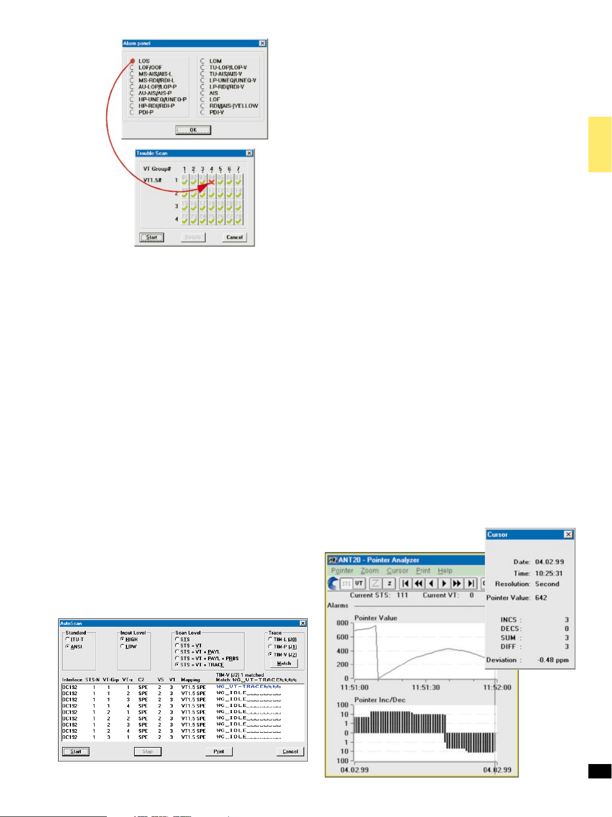
Figure 2: Trouble scan.
Automatic TROUBLE SCAN function (Figure 2)
The TROUBLE SCAN function permits sequential testing of all VT1.5
or VT2 channels in a SONET signal. The ANT-20SE receiver checks for
alarms in the receive signal, the SONET structure and all channels.
The results (OK/not OK) for each channel are entered in a matrix.
A detailed alarm history can be displayed by selecting a channel from
the matrix.
Only the receive channels are switched during a TROUBLE SCAN.
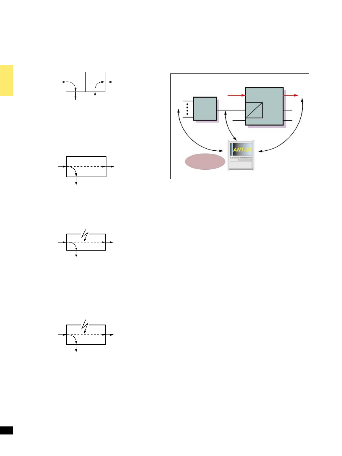
AutoScan function (Figure 3)
This automatic ªAutoScanº function allows you to rapidly check the
signal structure, the mapping used, the trace identifier and the payload
± even with mixed mapped signals.
The ANT-20SE receiver analyzes the incoming received signal and provides a clear overview of all the signals present in the composite receive
signal. The variable scan depth setting allows even complex signal
structures to be resolved and displayed clearly. All the displayed results
can be printed out.
Automatic SEARCH function
Channel shifts in the payload may occur when measuring complex network elements, depending on the configuration of the device under
test. The SEARCH function permits rapid automatic location of the
test channel (VT1.5 or VT2 with defined PRBS) in the payload of a
SONET signal.
The ANT-20SE receiver checks for alarms in the receive signal, the
SDH structure and all channels, and for synchronization of the selected
test pattern in all channels. The results (OK/not OK) for each channel
are entered in a matrix.
In-service measurements (ISM)
Simultaneous ISM of the near-end and far-end of a selected path
±
Near-end . . . . . . . . . . . . . . . . . . . . . . . B1, B2, B3, BIP-V, CRC-6
±
Far-end . . . . . . . . . . . . . . . . . . . . . . . . . . . . REI-L, REI-P, REI-V
DS1, DS3 events ..................... Fbit, parity, FEBE, C parity
Out-of-service measurements (OOS)
OOS evaluation using bit errors in test pattern
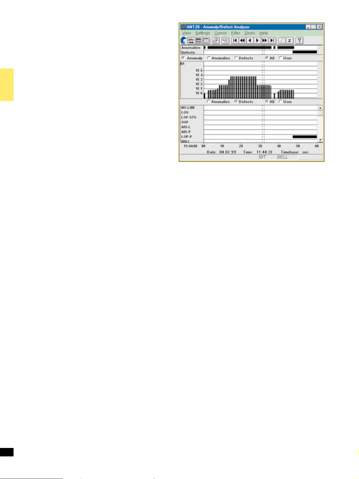
Analysis of STS-1 and VT pointer actions (Figure 4)
Display of
±
Number of pointer operations:
Increment, Decrement, Sum (Increment + Decrement),
Difference (Increment ± Decrement)
±
Pointer value
Clock frequency measurement
The deviation of the input signal clock frequency from the nominal
frequency is displayed in ppm.
Figure 4: Graphic pointers. Display showing additional evaluation
of cursor position.
Figure 3: AutoScan.
5
Page 6
Delay measurement
Delay measurements are used for aligning satellite hops and testing the
maximum permitted delay times for storage exchange and cross-connect systems and for checking the loop circuits in regenerators.
The ANT-20SE measures the time taken to transmit the test pattern
from the generator through the section under test and back to the
receiver. The measurement is made on the test patterns in a selected
channel, or in the tributaries (SONET; bulk signal or asynchronous),
or on the selected channel of the lowest hierarchy level of asynchronous
multiplex systems.
To avoid ambiguities in the measurement, two measurement times are
provided.
Measurement range
Bit rates from 34 to 155 Mbit/s ........................1msto1s
Bit rate 1.5 Mbit/s ................................. 10msto5s
Alarm detection
All alarms are evaluated and displayed in parallel
Alarm types ...................................LOS,OOF,LOF
Additionally, for STS . . ...............AIS-L, RDI-L, AIS-P, LOP-P,
NDF-P, RDI-P, UNEQ-P, TIM-P, PLM-P
Additionally, for DS1, DS3 ..............LSS, AIS, RAI (YELLOW),
IDLE (DS3), FEAC (DS3)
Figure 5: Histogram results display.
TOH and POH evaluation
±
Display of complete TOH and POH, e.g. interpretation of
APS information in K1 and K2
For the bytes E1, E2, F1, F2 and byte groups D1 to D3 and D4 to D12:
±
BERT using test pattern from the generator unit
±
Output of the data signal via the V.11 interface (also for K1, K2,
K3, N1 and N2)
For the Trace Identifier
±
J0 . . . . . . . . . . . . . . . . . . . . . . display of 16 byte ASCII sequence
±
J1, J2 . . . . . . . . . . . . . . . . display of 16 or 64 byte ASCII sequence
Measurement interval
Variable ...................................1second to 99 days
Measurement start .................... manual or automatic timer
Measurement stop ....................manual or automatic timer
(user setting)
(user setting)
Memory for errors, pointer operations and alarms
Resolution of error events and pointers . ...................... 1s
Alarm resolution ......................................100ms
Off-line analysis software
The software runs on standard PCs and permits comprehensive
analysis of stored ANT-20SE results. After loading the results, the
ANT-20SE settings during the measurement and the stored results can
be accessed. Zoom and filter functions allow detailed evaluations. The
processed results can be exported in CSV format for importing into
other programs such as MS Excel or MS Word for Windows for
producing documentation.
Graphical display (histogram) (Figure 5)
Display of errors, pointer operations / values and alarms as bargraphs
vs. time
Units, time axis ..............................seconds, minutes,
15 minutes, hours, days
Tabular display
Display of all alarm and error events with time stamp
Result printout
ANT-20SE supports a variety of dot-matrix, inkjet and laser printers
(Windows Print Manager)
Printer interfaces
Serial . .......................................... V.24/RS232
Parallel ........................... Centronics/EPP/IEEE P 1284
Result export
Results are stored in a database and can be processed using standard
PC software
Instrument operation
ANT-20SE is operated using the standard MicrosoftâWindows
graphical user interface.
Operation is menu-controlled using the touchscreen.
A mouse can also be connected if desired.
Application selection and storage
ANT-20SE includes an applications library to which customer-specific
applications can be added.
All applications are stored internally on the built-in hard disk drive
and can be copied to any other ANT-20SE via floppy disk or super disk.
Easy to use filter functions allow quick selection of the desired
application.
TM
Results display and instrument operation
Numerical display
Display of absolute and relative values for all error types
6
Intermediate results . . . .......................every 1 s to 99 min
Touchscreen display
A large display screen is available for the ANT-20SE:
Color TFT screen ..............................10.4@, 256 colors
Resolution ..................... 6406480 pixels (VGA standard)
The touchscreen allows very easy point and shoot operation.
Page 7

Built-in PC
ANT-20SE uses a Pentium PC as internal controller so that standard
PC applications can also be run on the instrument.
RAM capacity ........................................64MB
LS-120 drive .................................... 3.5@, 120 MB
Hard disk drive ........................................ 6GB
USB interface, 10/100 Mbit/s Ethernet interface are included.
Keyboard
Full keyboard for text input, extended PC applications and future
requirements. The keyboard is protected by a fold back cover.
An additional connector is provided for a standard PC keyboard.
External display connector
Simultaneous display with built-in screen
Interface ...................................... VGAstandard
PCMCIA interface
Type ............................ PCMCIA2.1typesI,IIandIII
The PCMCIA interface provides access to GPIB, LANs, etc.,
via adapter cards.
Byte capture TOH and POH
To analyze the TOH/POH functions, it is necessary to capture
individual bytes vs. time, allowing detection of errors or short-term
changes with frame level precision.
The Capture function is started by a selectable trigger.
Values for a selected byte are stored and can be accessed subsequently
in a table of values.
Particularly in capturing the APS sequences, the bytes (K1, K2) are
displayed as an abbreviation of the standard commands.
The function also allows recording of the N1 or N2 bytes
for evaluation of ªTandem Connectionº information.
H4 sequences can also be analyzed very easily.
The results can be printed or exported.
Capture bytes for STS-1/-3/-3c, el. & opt ........ allTOH/POH bytes
OC-Nel.&opt............. allTOH/POH bytes,
channel 1 except A1, A2, B1
Storage depth for a byte .................................. 266
K1,K2 .................................. 200
Trigger events ................. AIS-L, AIS-V, AIS-P, RDI-L, LOP-P,
editable value in trigger byte
Capture resolution ............................. frame precision
Power outage function
In the event of an AC line power failure during a measurement,
ANT-20SE saves all data.
As soon as the AC line voltage is reestablished, the measurement is
resumed. Previous results are retained and the time of the power failure
is recorded along with other events.
General specifications
Power supply (nominal range of use)
AC line voltage,
automatic switching . . ............. 100to127Vand220to240V
AC line frequency ...................................50/60 Hz
Power consumption (all options fitted) . .............. max.500VA
Safety class to IEC 1010-1 ............................... Class I
Ambient temperature
Nominal range of use . ........... 41Fto104 F (+5 C to + 40 C)
Storage and transport range ...... ±4Fto158 F (± 20 C to +70 C)
Dimensions (w6h6d)inmm ........... approx. 32063506280
in inches ......... approx. 12.66 13.8611
Weight ................................... approx. 15 kg/22 lb
APS time measurement
In synchronous networks, a defined maximum switch-over time is
necessary for the traffic in case of a fault.
To verify compliance with this requirement, the ANT-20SE measures
the switch-over time with 1 ms resolution.
The result can be printed.
Criteria for the time measurement ............ AIS-L, AIS-V, AIS-P,
Max. measurable switch-over time ........................... 2s
Resolution ...................... ......................1ms
Allowable error rate for user signal .................... 52610
bit error
±4
Add SDH BN 3060/90.04
BERT (2, 8, 34, 140 Mbit/s)
Signal structure and interfaces for generator and receiver:
Framed and unframed test patterns
Additionally, for coaxial input/output
Bit rate, line code .................2048, 8448, 34 368 kbit/s, HDB3
Bit rate, line code ...........................139264kbit/s, CMI
Additionally, for balanced input/output
Bit rate, line code ............................2048 kbit/s, HDB3
C4 mapping
(140 Mbit/s in STM-1 and STS-3c)
See ANT-20SE SDH datasheet for details.
Options
Extended SONET testing BN 3060/90.02
VT6 SPE mapping
(6 Mbit/s unframed/Bulk in STS-1)
STS-1 SPE and STM-0 mapping
Errors and alarms as for mainframe instrument
VT2 SPE and STM-0 mapping
E1 in STS-1 and 2 Mbit/s in STM-0
Modes ................ asynchronous, byte synchronous (floating)
Error insertion and alarm generation as for VT1.5 SPE mapping.
STS-3c mapping
(140 Mbit/s in STS-3c and STM-1)
C11 mapping
(1.5 Mbit/s in STM-1, AU-3/AU-4)
See ANT-20SE SDH datasheet for details.
C12 mapping
(2 Mbit/s in STM-1, AU-3/AU-4)
See ANT-20SE SDH datasheet for details.
C3 mapping
(34 Mbit/s in STM-1, AU-3/AU-4)
C3 mapping
(45 Mbit/s in STM-1, AU-3/AU-4)
See ANT-20SE SDH datasheet for details.
C2 mapping
(6 Mbit/s unframed/Bulk in STM-1)
See ANT-20SE SDH datasheet for details.
7
Page 8
Drop & Insert BN 3060/90.10
This option provides the following functions:
1. Generator and receiver operate independently
as mapper and demapper. The DS1/DS3 signal from a selected
channel is dropped from the receive signal and output to a
connector. An external or internal DS1/DS3 signal is inserted into
the transmit signal.
M13 MUX/DEMUX chain BN 3060/90.12
M13 multiplexers are used in North America in hybrid networks and
synchronous system cross-connects. This option provides n6DS0 to
DS3 multiplex and demultiplex functions. The output signal is fed to
the electrical interface and is available as payload in mappings
(requires options BN 3060/90.02 or BN 3060/90.04).
Alarms and errors can be generated and analyzed.
OC-M/STM-N
e/o
Asynchronous tributary
OC-M/STM-N
e/o
2. Through mode:
The received signal is looped through the ANT-20SE and re-
transmitted (generator and receiver coupled). The DS1/DS3 signal
from a selected channel may be dropped from the receive signal and
output to a connector. An internal DS1/DS3 signal may be inserted
into the transmit signal. The ANT-20SE can operate here as an active
signal monitor without affecting the signal.
OC-M/STM-N
e/o
Asynchronous tributary
OC-M/STM-N
e/o
3. Through mode jittering:
The looped-through DS1/DS3 or SONET signal can also be jittered
using the Jitter Generator option. This applies to all jitter
frequencies up to 622 Mbit/s depending on the jitter option fitted.
Jitter
OC-M/STM-N
e/o
OC-M/STM-N
e/o
W-DCS
OC-N
DS1
DS1
MUX
M13
DS1
Built-in
M13 MUX/DEMUX
OC-N
DS3
DS1
DS3/DS1
Cross connect
DS3
DS1
OC-N
DS1,
VT1.5
Figure 6: Testing hybrid systems with M13 MUX/DEMUX.
64k/140M MUX/DEMUX chain BN 3060/90.11
This option provides n664 kbit/s to 140 Mbit/s multiplex and
demultiplex functions. The output signal is fed to the electrical interface (requires option BN 3060/90.04) and is available as payload in
mappings (requires option BN 3060/90.04).
Alarms and errors can be generated and analyzed.
Asynchronous tributary
4. Error insertion in through mode:
The looped-through synchronous signal can be manipulated if
required:
± Overwriting bytes in the TOH
(except B1, B2, H1 to H3)
± Anomaly insertion
± Defect generation by programming the TOH
Error/Alarm
OC-M/STM-N
e/o
Asynchronous tributary
5. Block and Replace (B & R)
For this function, the ANT-20SE is looped into the working fiber of
a ring. B&R allows replacement of a synchronous tributary (e.g.
STS-1 including TOH, POH and payload) in a OC-N signal. This
can then be measured by the ANT-20SE from the ring. By inserting
specific errors, the error thresholds of the APS mechanism in the
system can be tested.
Additional input and output for tributary signals
75 O, coaxial BNC; line codes as for mainframe instrument
Input and output for balanced tributary signals: Use balanced
8
connectors on mainframe
OC-M/STM-N
e/o
Page 9

Optical Interfaces
All of the optical interfaces are intended for single-mode fibers. Acterna
offers a complete line of optical test adapters. Select one test adapter
each for the generator and receiver from the ordering information in
this data sheet. All optical interface options include the required
number of test adapters.
The STM-0 optical interface requires the option ªAdd SONETº.
Optical Modules up to 155 Mbit/s
Optical OC-1/3, STM-0/1, 1310 nm BN 3060/91.01
Optical OC-1/3, STM-0/1, 1310& 1550 nm BN 3060/91.02
Bit rate of TX and RX signal ....................... 155520kbit/s
additionally, for STS-1/STM-0 mappings ...........51840kbit/s
Line code..................................... scrambled NRZ
Generator unit
The generator meets the requirements of Telcordia GR-253,
ANSI T1.105.06 (ITU-T Rec. G.957, Tables 2 and 3).
Classes LR-1, LR-2, LR-3 (L1.1, L1.2 and L1.3) are covered.
There are two options for adapting to the required wavelength:
Wavelength ........................................1310 nm,
1310 & 1550 nm (switchable in the instrument)
Output level ................................. 0dBm+2/±3dB
with 1310 & 1550 nm option ................. 0dBm+2/±3.5dB
Receiver unit
The receiver unit meets the specifications of Telcordia GR-253,
ANSI T1.105.06 (ITU-T Rec. G. 957) and fulfills classes IR-1, IR-2
(S1.1 and S1.2).
Wavelength range ............................. 1100 to 1580 nm
Input sensitivity ................................±8to±28dBm
(± 8 to ± 34 dBm typ.)
Display of optical input level
Resolution .............................................1dB
155 Mbit/s electrical interface
for connecting the ANT-20SE to STM-1/STS-3 monitor points
Line code..................................... scrambled NRZ
Input voltage (peak-peak) ............................ 0.2to1V
Unbalanced input
Connector/impedance . ............................. SMA/50O
Optical Modules up to 622 Mbit/s
Optical OC-1/3/12, STM-0/1/4, 1310 nm BN 3060/91.11
Optical OC-1/3/12,
STM-0/1/4, 1310& 1550 nm BN 3060/91.12
Bit rate of TX and
RX signal.......................... 155520kbit/s, 622 080 kbit/s
additionally, for STS-1/STM-0 mappings ...........51840kbit/s
Line code..................................... scrambled NRZ
There are two options for adapting to the required wavelength:
Wavelength ........................................1310 nm,
Output level ................................. 0dBm+2/±3dB
with 1310 & 1550 nm option ................. 0dBm+2/±3.5dB
Generation of OC-12 TX signal
In instruments with STS-1 mappings
The OC-12 TX signal consists of
±
one internally generated STS-1 tributary signal with the other
11 tributaries filled with UNEQ or
±
one internally generated STS-3c tributary signal with the other
three tributaries filled with UNEQ (with STS-3c mapping option
or ATM Basic Option BN 3060/90.50).
Generation of STM-4 TX signal
In instruments with STM-1 mappings
The STM-4 TX signal consists of
±
four identical STM-1 tributary signals (AU-4), or
±
one internally generated STM-1 tributary signal with the other
three tributaries filled with UNEQ.
Contents of the OC-12/STM-4 overhead bytes
For all bytes except B1, B2 and H1 to H3:
±
The content of each byte is statically programmable or a user
defined byte-sequence p in m in n (p frames in m frames and the
entire sequence repeated n times) can be inserted.
For the E1, E2, F1 bytes and the DCC channels
D1 to D3 and D4 to D12:
±
Transmission of a test pattern with bit error insertion (see mainframe for pattern selection)
±
Insertion of an external data signal (via the V.11 interface)
For the K1, K2, N1, N2 bytes:
±
Insertion of the data signal via the V.11 interface
For the J0 bytes:
±
Transmission of a 16-byte sequence, with CRC
Error insertion
Error types ..............................B1andB2parity error
additionally, for OC-12 ................................. REI-L
Triggering
Single errors or error ratio ................... 2610
for B1 parity errors ..........................2610±4to 1610
Burst error: m anomalies in n periods
For FAS, B1, B2, B3, REI-L, REI-P . . . ...... m=1to4.86106 and
Alarm generation, dynamic
Alarm types for OC-12 .......................LOF,AIS-L, RDI-L
m alarms in n frames . . ................. m=1ton-1, n
or
t1 alarm active, t2 alarm passive .................... t1=0to60s,
forSTM-4................................MS-REI
forSTM-4 ................... LOF,MS-AIS, MS-RDI
1310 & 1550 nm (switchable in the instrument)
±3
to 1610
n = 2 to 8001 frames or 0.2 s to 600 s
t2 = 0 to 600 s
max
±10
±10
= 8000
Generator unit
The generator meets the requirements of Telcordia GR 253,
ANSI T1.105.06 (ITU-T Rec. G. 957, Tables 2 and 3).
Classes LR-1, LR-2, LR-3 (L1.1, L1.2, L1.3, L4.1, L4.2 and L4.3) are
covered.
Alarm generation, static (on/off)
Alarm types ....................................... LOS,LOF
additionally, for OC-12 .....................AIS-L, RDI-L, TIM-L
forSTM-4................ MS-AIS, MS-RDI, RS-TIM
Insertion on/off
9
Page 10

Receiver unit
The receiver unit meets the specifications of Telcordia GR 253,
ANSI T1.105.06 (ITU-T Rec. G.957) and fulfills classes IR-1, IR-2,
LR-1, LR-2, LR-3 (S1.1, S1.2, S4.1, S4.2, L4.1, L4.2 and L4.3).
Wavelength range ............................. 1100 to 1580 nm
Input sensitivity, OC-1/3/12 STM-1/-4, . ............±8to±28dBm
(± 8 to ± 34 dBm typ.)
Display of optical input level
Resolution .............................................1dB
The ANT-20SE demultiplexes one selectable STS-3c/STS-1 or
STM-1 tributary from the OC-12/OC-3 or STM-4
RX signal and feeds it to the internal processor for evaluation.
Measurement types
Error measurements
Error types ....................................B1parity error,
B2 parity error of all STM-1/STS-1/STS-3c signals,
MS-REI/REI-L
Alarm detection
Alarm types .............................. LOS,LOF,OOF,LTI
additionally, for OC-12 .................... AIS-L, RDI-L, TIM-L
forSTM-4................ MS-AIS, MS-RDI, RS-TIM
Option OC-12c/STM-4c
Virtual Concatenation BN 3060/90.92
Only in conjunction with BN 3060/90.90 or BN 3060/90.91
Signal structure
STM-4 to ITU-T G.707
Virtual concatenation with 4 AU-4 pointers
Generation of pointer actions
Manipulations on pointer #1 see mainframe
Setting of delta values for pointers #2, #3, #4
Pointer analysis
For pointer #1 ................................. seemainframe
Delta values (maximum, minimum) . . . ....................+40
for pointers #2, #3, #4
POH generation/analysi s
POH#1 ...................................... seemainframe
POH#2,#3,#4..........................static setting of all bytes
except B3
Automatic B3 generation for VC-4 #1, #2, #3, #4
Overhead evaluation
±
Display of the complete overhead of a selectable
STM-1/STS-1/STS-3c signal
For the E1, E2, F1 bytes and the DCC channels
D1 to D3 and D4 to D12:
±
BERT using a test pattern from the generator unit
±
Output of the data signal via the V.11 interface
For the K1, K2, N1, N2 bytes:
±
Data signal output via the V.11 interface
For the J0 byte:
±
Display of 15-byte sequences in ASCII.
155/622 Mbit/s electrical interface
For connecting the ANT-20SE to OC-3/STM-1 and
OC-12/STM-4 monitor points
Line code..................................... scrambled NRZ
Input voltage (peak-peak) ............................ 0.2to1V
Coaxial input
Connector / impedance .............................SMA/50O
Concatenated Mappings 622 Mbit/s
Option OC-12c/STM-4c BERT BN 3060/90.90
Only in conjunction with BN 3060/91.11 or BN 3060/91.12
Contiguous concatenation signal structure to ANSI T1.105.02
and G.707.
Error measurement to O.150
Test pattern .............................. PRBS-31, IPRBS-31,
Programmable word
Length .............................................. 16bits
Error insertion
Bit errors in test pattern, single error or
error ratio ................................ 1610
Error measurement and alarm detection
10
Bit errors and AIS in test pattern
PRBS-23, IPRBS-23,
PRBS-15, IPRBS-15
PRBS-20,
±2
to 1610
Option OC-12c/STM-4c ATM-Testing BN 3060/90.91
Only in conjuction with BN 3060/90.50 and BN 3060/91.11 or BN 3060/91.12
See chapter ªATM optionsº for further details.
Optical Modules up to 2488 Mbit/s
All optical packages include OC-12c/STM-4c Bulk (BN 3060/90.90),
OC-48c/STM-16c Bulk (BN 3060/90.93) and 4 optical adapters.
Optical OC-1/3/12/48,
STM-0/1/4/16, 1310 nm BN 3060/90.55
Optical OC-1/3/12/48,
STM-0/1/4/16, 1550 nm BN 3060/90.56
Optical OC-1/3/12/48,
STM-0/1/4/16, 1310 &1550 nm BN 3060/90.57
Optical OC-1/-3/-12, 1310 nm,
OC-48, 1550 nm,
STM-0/1/4, 1310 nm,
STM-16, 1550 nm BN 3060/90.58
Optical Modules 2488 Mbit/s
Optical OC-48, STM-16, 1310 nm BN 3060/91.51
Optical OC-48, STM-16, 1550 nm BN 3060/91.50
Optical OC-48, STM-16,
1310/1550 nm switchable BN 3060/91.52
One 2.5 Gbit/s module can be fitted in the extension slot of the
ANT-20SE.
The optical interfaces meet the specifications of Telcordia
TA-NWT-000253 I.6 (Table 4 ± 9, 4±10) and ITU-T Recommendation
±9
G.957 (Table 4).
Classes IR-2, LR-2, LR-3 (Telcordia) or S-16.2, L-16.2, L-16.3 (ITU-T)
are fulfilled at 1550 nm; classes IR-1, LR-1 (Telcordia) or S-16.1, L-16.1
(G.957) are fulfilled at 1310 nm.
Page 11

Generator
Optical interfaces
Wavelengths ................................ 1310 nm, 1550 nm
Output level at 1310 nm and 1550 nm . . .......... 0dBm+0/±2dB
Line code .................................... scrambled NRZ
Electrical interfaces
Line code..................................... scrambled NRZ
Output voltage (peak-peak).............................
Connector/impedance . ............................. SMA/50 O
Clock generator
Internal, accuracy ...................................+2 ppm
Offset. . ...........................................+50 ppm
Synchronization from external signal as for mainframe
Generation of OC-48 TX signal
In instruments with STS-1/STS-3c mappings
The OC-48 signal consists of one or more internally generated
tributaries plus several tributaries filled with UNEQ (or non-specific
UNEQ)
±
48 identical STS-1
±
One STS-1 tributary and 476UNEQ/non specific
±
16 identical STS-3c (Option BN 3060/90.02 required)
±
One STS-3c tributary (Option BN 3060/90.02 required)
and 156UNEQ/non specific
±
Four identical STS-12c (Option BN 3060/90.90 required)
±
One STS-12c tributary (Option BN 3060/90.90 required)
and 36UNEQ/non specific
Generation of STM-16 TX signal
In instruments with STM-1 mappings
The STM-16 signal consists of one or more internally generated
tributaries plus several tributaries filled with
UNEQ (or non-specific UNEQ)
±
16 identical STM-1
±
One STM-1 tributary and 156UNEQ/non specific
±
Four identical STM-4c (Option BN 3060/90.90 required)
±
One STM-4c tributary (Option BN 3060/90.90 required)
and 36UNEQ/non specific
Contents of OC-48/STM-16 overhead bytes
For all bytes except B1, B2 and H1 through to H3:
±
The contents of the bytes in all SOH/TOH are statically
programmable
For the bytes E1, E2, F1 and the DCC channels D1 to D3 and
D4 to D12:
±
Transmission of a test pattern and bit error insertion
(see mainframe for pattern selection)
±
Insertion of an externally-generated data signal
(via V.11 interface)
For the K1, K2, N1, N2 bytes:
±
Insertion of an external data signal via the V.11 interface
For the J0 byte:
±
Transmission of a 16-bit sequence with CRC
Error insertion
Error types ................................ B1,B2parity errors
Single error or error rate B1 ..................2610
B2 ..................2610±3to 1610
additionally, for OC-48 ..................................REI-L
forSTM-16.............................. MS-REI
Single error or error rate .....................2610
Alarm generation, dynamic
Alarm types for OC-48 .......................LOF,AIS-L, RDI-L
forSTM-16 .................. LOF,MS-AIS, MS-RDI
or 1310/1550 nm switchable
4
0.6 V
-
±5
±3
to 1610
to 1610
±10
±10
±10
m alarms in n frames . . ................. m=1ton-1,n
max
= 8000
or
t1 alarm active, t2 alarm passive .................... t1=0to60s,
t2 = 0 to 600 s
Alarm generation, static (on/off)
Alarm types ....................................... LOS,LOF
additionally, for OC-48 ............................AIS-L, RDI-L
forSTM-16.......................MS-AIS, MS-RDI
Receiver
Optical interfaces
Wavelength ................................. 1260 to 1580 nm
Line code..................................... scrambled NRZ
Sensitivity .................................... ±28to±8dBm
Input overload .....................................4±8 dBm
Display of optical input level
Range . ...................................... ±30to±8dBm
Resolution .............................................1dB
Electrical interfaces
Line code .................................... scrambled NRZ
Input voltage (peak-peak) ............................ 0.3to1V
Connector/impedance . ............................. SMA/50 O
A selectable STM-1, STS-1 or STS-3c channel is fed to the internal
evaluation circuits by demultiplexing from the input signal.
Error measurement
Error types ............................ B1parity error, MS-REI,
B2 parity sum error over
all STM-1/STS-1/STS-3c channels
Evaluation (bit/block errors) ....................error rate, count
Error event resolution . .................................... 1s
Alarm detection
Alarm typs ................................... LOS,LOF,OOF
additionally, for OC-48 .....................AIS-L, RDI-L, TIM-L
forSTM-16............... MS-AIS, MS-RDI, RS-TIM
Alarm event resolution ................................ 100ms
TOH/SOH evaluation
Display of complete overhead
For the bytes E1, E2, F1 and the DCC channels D1 to D3 and D4
to D12:
±
BERT using test pattern from generator unit
±
Output of the data signal via the V.11 interface
For the K1, K2, N1, N2 bytes:
±
Data signal output via the V.11 interface
For the J0 byte:
±
Display of 15-byte sequences in ASCII format
Concatenated Mapping 2488 Mbit/s
Option OC-48c/STM-16c BERT BN 3060/90.93
Only in conjunction with BN 3060/91.50 to /91.53
Contiguous concatenation signal structure to ANSI T1.105.02 and
G.707.
Error measurement to O.150
Test pattern ............................... PRBS-31, IPRBS-31
Programmable word
Length . ..............................................16bits
Error insertion
Bit errors in test pattern, single error or
error ratio ................................ 1610
PRBS-23, IPRBS-23
±3
to 1610
±9
11
Page 12

Alarm generation:
AU-AIS, AIS-C1...AIS-C16,
AU-LOP, LOP-C1...LOP-C16
Error measurement and alarm detection:
AU-AIS, AU-LOP
Bit errors
Automatic Protection Switching
Sensor: MS-AIS, AU-AIS
Solutions for 10 Gbit/s
With the new ANT-10Gig we provide a 10 Gbit/s solution which covers
OC-192 as well as STM-64. The ANT-10Gig allows testing at the
highest line bit rate and in all mappings below and offers optionally all
testing down to n664 kbit/s.
For detailed information please refer to data sheet ªANT-10Gigº.
The ANT-20SE is prepared for upgrades towards STM-64/OC-192.
Further options
Optical Power Splitter (90%/10 %) BN 3060/91.05
The Optical Power Splitter is built into the ANT-20SE.
Three optical test adapters are required to operate it; please indicate
your choice.
OLA-15 Optical Attenuator (variable) BN 2239/01
One application of OLA-15 is in
line-up of optical links, where line
interruptions are simulated for bit
error testing. The device is also useful
when measuring the sensitivity of
optical receivers. With its wide variable
attenuation range and highly accurate
and reproducible attenuation settings,
the OLA-15 is an ideal companion to
the ANT-20SE.
Calibrated at ............................... 1310 and 1550 nm
Attenuation range ..................................3to60dB
Resolution .......................................... 0.05 dB
See OLA-15 data sheet for details.
The Optical Power Splitter provides an optical monitor point. The
input signal is passed through to the output transparently.
Light energy forwarded ..................approx. 90 % (±0.45 dB)
Light energy coupled out ................. approx. 10 % (±10 dB)
The Optical Power Splitter operates in the following ranges:
Wavelengths ............... 1260 to 1360 nm and 1500 to 1600 nm
12
Page 13

Jitter and Wander Options
Standards
Jitter generation and jitter/wander analysis are in accordance with:
±
Telcordia GR-253, GR-499, GR-1244
±
ANSI T1.101, T1.102, T1.105.03,T1.403, T1.404, T1.105.09
±
ITU-T G.783, G.823, G.824, G.825, O.171, O.172
±
ETSI ETS 300 462-1 to -6, ETS 300 417-1-1, EN 302 084
O.172 Jitter/Wander
up to 155 Mbit/s BN 3060/91.30
Jitter generator
Fully complies with or exceeds the requirements of ITU-T O.172.
Bit rates
Generates jitter at all bit rates included in the mainframe configuration
up to 155 520 kbit/s.
TX signals .................. alltest patterns and frame structures
Built-in modulation generator (sinewave) ......... 0.1Hzto5MHz
External modulation . . ..........................0Hzto5MHz
Jitter amplitude ...................................upto64UI
A2
UI
pp
included in the mainframe configuration
Low-pass filters ......... 40,60,100, 400, 800, 1300, 3500, 5000 kHz
Filter characteristics . . . ............................ asperO.172
Measurement ranges
Peak-peak
Range I/Resolution . ................... 0to1.6UIpp/1 mUIpp
Range II/Resolution . ...................0to20UIpp/10 mUIpp
Range III/Resolution .................0to200UIpp/100 mUIpp
RMS
Range I/Resolution . ................... 0to0.8UIpp/1 mUIpp
Range II/Resolution . .................. 0to10UIpp/10 mUIpp
Range III/Resolution .................0to100UIpp/100 mUIpp
Measurement accuracy ............................ asperO.172
Demodulator output
75 O, BNC socket
Range I (0 to 1.6 UIpp) .............................. 1V/UIpp
Range II (0 to 20 UIpp) ............................. 0.1V/UIpp
Range III (0 to 200 UIpp) .......................... 0.01 V/UIpp
Wander Generator
Fully complies with or exceeds the requirements of ITU-T O.172
Bit rates
Wander generation at all implemented bit rates up to 155 Mbit/s
according to the equipment level of the instrument.
Amplitude range ............................. upto200000UI
Frequency range ..............................10mHz to 10 Hz
Accuracy ........................................ asperO.172
Resolution ........................................... 1mHz
A1
f1 f2
Clock rate/kHz A1 A2 f1 / Hz f2 / Hz f3 / kHz
1 544
2 048 1560 200
6 312 940 120
8 448 6250 800
34 368 27 k 3 500
44 736 35 k 4 500
51 840 27 k 3 500
139 264 39 k 5 000
155 520 39 k 5 000
622 080 * 1.0 256 20 k 5 000
* Requires option BN 3060/91.31
Modulator input
75 O, BNC socket
Voltage required ....................................0to2Vpp
Error limits ..................................... asperO.172
0.5 64 0.1
log f
625 80
f3
Jitter Analyzer
Jitter measurement at all bit rates included in the mainframe
configuration up to 155 520 kbit/s.
Wander Analyzer
Fully complies with or exceeds the requirements of ITU-T O.172
For all bit rates up to 155 Mbit/s according to the equipment level of
the instrument.
Other sampling rates in addition to the 30/s rate are available for
detailed analysis versus time:
Sampling rate ± Low-pass filter ±
Test duration .............................1/s-0.1Hz-99days
Amplitude range .............................+1nsto+10
Measurement accuracy ............................ asperO.172
Accessory: ªStandard Frequency Sourceº for wander applications, see
end of chapter
30/s - 10 Hz - 99 h
60/s - 20 Hz - 99 h
300/s - 100 Hz - 5000 s
6
O.172 Jitter/Wander
up to 622 Mbit/s BN 3060/91.31
Jitter Generator
Jitter modulation of STM-4 TX signals.
Built-in modulation generator (sinewave) ......... 0.1Hzto5MHz
External modulation . . ..........................0Hzto5MHz
Jitter amplitude ..................................upto256UI
s
Built-in filters
High-pass filters ................ 0.1, 2, 4, 10, 20, 40, 100, 200, 400,
500, 700 Hz,
1, 3, 8, 10, 12, 18, 20, 30, 65, 80, 250 kHz
Jitter modulation of externally-generated
signals in Through mode
Externally-generated signals can be jittered in Through mode when the
D&I option is included.
13
Page 14

This applies to all bit rates included in the mainframe configuration at
the appropriate electrical and optical interfaces.
Built-in modulation generator (sinewave) ......... 0.1Hzto5MHz
External modulation . . ..........................0Hzto5MHz
Jitter amplitude ....................asforjitter generator in UIpp
O.172 Jitter/Wander
up to 2488 Mbit/s BN 3060/91.32
Jitter Generator
Fully complies with or exceeds the requirements of ITU-T O.172
Jitter Analyzer
Measurement range
Peak-peak
Range I/Resolution . ................... 0to6.4UIpp/1 mUIpp
Range II/Resolution . .................. 0to80UIpp/10 mUIpp
Range III/Resolution .................0to800UIpp/100 mUIpp
RMS
Range I/Resolution . ................... 0to3.2UIpp/1 mUIpp
Range II/Resolution . .................. 0to40UIpp/10 mUIpp
Range III/Resolution .................0to400UIpp/100 mUIpp
Measurement accuracy ............................ asperO.172
Demodulator output
75 O, BNC socket
Range I (0 to 6.4 UIpp) ............................ 0.25 V/UIpp
Range II (0 to 80 UIpp) ........................... 0.025 V/UIpp
Range III (0 to 800 UIpp) ........................ 0.0025 V/UIpp
Wander Generator
Fully complies with or exceeds the requirements of ITU-T O.172
Bit rates
Wander generation at all implemented bit rates up to 622 Mbit/s
according to the equipment level of the instrument.
Amplitude range ............................. upto200000UI
Frequency range ..............................10mHz to 10 Hz
Accuracy ........................................ asperO.172
Resolution ........................................... 1mHz
Bit rate ...................................... 2488320kbit/s
Generator signal ................... test patterns, frame structures
depend on instrument configuration
Built-in modulation generator (sinewave)
or external ................................. 0.1Hzto20MHz
Jitter amplitude ..................................upto800UI
A4
UIpp
A3
A2
A1
f0 f1 f2 f3 f4
Jitter frequency (log)
Bit rate/
kHz
2 488 320
ANT-20SE
A1/
A2/
A3/
A4/
UIpp
UIpp
UIpp
0.008 0.75 20 800 0.1 12.1 500 750 k 20 M
f0/Hzf1/Hzf2/Hzf3/Hzf4/
UIpp
Hz
Modulator input
75 O, BNC socket
Modulation frequency . ....................... 0.1Hzto20MHz
Required sinusoidal voltage ......................... 0to2Vpp
Error limits ..................................... asperO.172
Wander Analyzer
Fully complies with or exceeds the requirements of ITU-T O.172
Other sampling rates in addition to the 30/s rate are available for
detailed analysis versus time:
Sampling rate ± Low-pass filter ±
Test duration .............................1/s-0.1Hz-99days
Amplitude range .............................+1nsto+10
Measurement accuracy ............................ asperO.172
Reference signal input
Frequencies ............................1.544, 2.048, 5, 10 MHz
Bit rates .................................. 1.544, 2.048 Mbit/s
Balanced 110 O connector .............................Bantam
Clock input voltage
(sine or square wave) . . ...........................1.0to6.5Vpp
HDB3/B8ZS input voltage .........................+3V+10%
Coaxial 75 O connector ...................................BNC
Clock input voltage
(sine or square wave) . . ............................ 1.0to5Vpp
HDB3/B8ZS input voltage ......................+2.37 V+10%
Accessory: ªStandard Frequency Sourceº for wander applications, see
14
end of chapter
30/s - 10 Hz - 99 h
60/s - 20 Hz - 99 h
300/s - 100 Hz - 5000 s
Jitter modulation of external signals in Through mode
In Through mode, jitter can be superimposed on an external 2488
Mbit/s signal in conjunction with the D&I option.
Internal and external modulation,
jitter amplitude ............................. seejitter generator
Jitter Analyzer
6
Fully complies with or exceeds the requirements of ITU-T O.172
s
Bit rate ...................................... 2488320kbit/s
Measuring ranges
Range I/Resolution ........................ 0to2UIpp/1 mUIpp
Range II/Resolution . . . .................. 0to32UIpp/10 mUIpp
RMS Range I/Resolution .................. 0to1.0UIpp/1 mUIpp
RMS Range II/Resolution .................0to16UIpp/10 mUIpp
Built-in filters
as per Telcordia GR-253, ANSI T1.105.03, ITU-T O.172, G.825, G.813
High-pass filters .......................... 5kHz,12kHz,1MHz
Low-pass filter ...................................... 20MHz
The high-pass filters can be switched off.
Frequency range without high-pass filter
Meas. range I ....................................... 80Hz
Meas. range II ...................................... 10Hz
Page 15

Measuring modes ............................ seeJitter Analysis
Demodulator outpur
75 O, BNC socket
Output voltage
Meas. range I (0 to 2 UIpp) .......................... 1V/UIpp
Meas. range II (0 to 32 UIpp) ..................... 62.5 mV/UIpp
Automatic tests ................. likejitter meter up to 622 Mbit/s
Tolerance masks at
MTJ/F-MTJ .................. ANSIT1.105.03, Telcordia GR-253,
ITU-T G.825
JTF ................... Telcordia GR-253, ANSI T1.105.03 type A,
ITU-T G.958
Wander Generator
Fully complies with or exceeds the requirements
of ITU-T O.172
Amplitude range.............................. upto200000UI
Frequency range ..............................10mHz to 10 Hz
Accuracy ........................................ asperO.172
Resolution ........................................... 1mHz
Figure 7: Jitter peak-to-peak/RMS measurement.
Wander Analyzer
Other sampling rates in addition to the 30/s rate are
available for detailed analysis versus time:
Sampling rate ± Low-pass filter ±
Test duration .............................1/s-0.1Hz-99days
Amplitude range ..............................+1nsto+10
Measurement accuracy ............................ asperO.172
Evaluation capabilities
see Wander Analysis
Reference signal input
75 O, BNC socket
Frequencies ............................1.544, 2.048, 5, 10 MHz
Input voltage .................................... 0.5to5Vpp
Input signal monitoring
(Loss of Timing Input). ....................................LTI
Accessory: ªStandard Frequency Sourceº for wander applications, see
end of chapter
30/s - 10 Hz - 99 h
60/s - 20 Hz - 99 h
300/s - 100 Hz - 5000 s
6
Jitter Analysis
Current values (continuous measurement)
Peak jitter value ......................................inUIpp
Positive peak value . . . ............................... inUI+p
Negative peak value . . . ............................... inUI±p
Maximum value (gated measurement)
Maximum peak jitter value .............................inUIpp
Maximum positive peak value ......................... inUI+p
Maximum negative peak value ......................... inUI±p
Result averaging (switchable) ........................... 1to5s
The ANT-20SE retains phase synchronicity even when pointer jitter
occurs (phase tolerance to O.172).
Phase hits
The instrument detects when the programmable threshold for positive
and negative jitter values is exceeded.
The result indicates how often this threshold was exceeded.
Setting range for positive and negative thresholds
(depending on measurement range) . . . .............. 0.1uptothe
half measurement range
Jitter versus time
This function is used to record variations of jitter with time.
It allows the positive and negative peak values or peak-to-peak values
to be displayed versus time.
Measured values have one second resolution. Measurement duration is
up to 99 days.
By simultaneously evaluating alarms and errors, corellations between
events can be quickly identified.
s
Figure 8: Jitter versus time display.
Clock jitter measurement
The ANT-20SE can also measure the jitter on the clock signals
(square-wave) at standard bit rates. All built-in bit rates with electrical
interfaces up to 155 Mbit/s can be measured.
RMS measurement
T1.105.03, GR-253, GR-499, G.958 (or G.783 rev.)
The RMS value is measured on-line and displayed in UI.
The peak jitter and RMS values can be displayed simultaneously; a
graph versus time is available for long-term analysis. An RMS filter
preset is available.
15
Page 16

Wander Analysis
Time Interval Error (TIE)
to O.172 ...............................numerical and graphical
Sampling rates ................. seeunder O.172 Wander Analyzer
for up to 622 Mbit/s
MTIE is additionally determined as a continually updated numerical
value.
Figure 9: On-line wander testing (TIE).
To prevent data loss or premature termination of long term measurements, the ANT-20SE checks the remaining space on the hard disk
before the start of the measurement. If necessary, the selected measurement time can be adjusted.
The TIE values are recorded and are then available for subsequent offline MTIE/TDEV evaluations. The values are also saved in .csv format
for documentation or further analysis.
Network synchronization quality is presented graphically using the
MTIE (Maximum Time Interval Error) and TDEV (Time DEViation)
parameters. To ensure correct assessment, the tolerance masks for PRC
(Primary Reference Clock), SSU (Synchronization Supply Unit), SEC
(Synchronous Equipment Clock) or PDH can be superimposed.
The results and masks can be printed out with additional user-defined
comments.
This software allows several TIE results to be displayed simultaneously.
Decisive details during long term measurements disappear in the
multitude of results. An effective zoom function is available for detailed
wander characteristic analysis.
Result printout and export
The results can be printed out and stored internally or on floppy disk.
The file format allows further processing using standard PC software.
Frequency offset and frequency drift rate (ANSI T1.101)
To ensure reliable operation when a clock source is in holdover mode,
the frequency characteristics must not exceed specific deviation limits
relative to an absolute reference source.
To verify this data, the ANT-20SE determines the following over the
selected measurement interval:
Frequency offset ...................................... inppm
Frequency drift rate . . . ............................... inppm/s
MRTIE ± Relative MTIE (G.823 and EN 302 084)
If the reference is unavailable (too far away) when analyzing the wander
of asynchronous signals, the MTIE analysis may have a superimposed
frequency offset.
This offset depends on the difference between the signal and local
reference clocks.
The MRTIE measurement subtracts the frequency offset from the result
so that the ªactualº wander characteristic is shown.
MTIE/TDEV Off-line Analysis Evaluation
Software
This software provides extended off-line statistical analysis facilities for
the results of wander measurements.
TIE values results obtained using the ANT-20SE are analyzed according
to ANSI T1.101, Telcordia GR-1244, ETSI ETS 300 462, EN 302 084,
ITU-T O.172, G.810 to G.813.
Figure 10: Display of MTIE/TDEV results and comparison
16
against masks.
Accessory for wander analysis
Standard frequency source .....................seeendofchapter
Automatic Measurements
The following automatic measurements can be run for all standard bit
rates and interfaces included in the mainframe configuration
(electrical/optical) up to 2488 Mbit/s.
Automatic determination of selective Jitter Transfer
Function, JTF
Telcordia GR-499, GR-253, ANSI T1.105.03, ITU-T G.958
The Jitter Transfer Function indicates the ratio of the jitter amplitude
at the output of the device under test to that at the input at various
frequencies.
This determines whether the device under test reduces or amplifies
input jitter and at which frequencies. After a calibration measurement
to minimize intrinsic errors, the ANT-20SE outputs a pre-selected jitter
amplitude at various frequencies and measures selectively the jitter
amplitude at the output of the device under test.
The ratio of the amplitudes in dB is the Jitter Transfer Function.
The preselected amplitudes correspond to the mask for maximum
permitted input jitter. The jitter frequencies and amplitudes can also be
edited. The calibration values can be saved and used again for other
measurements.
Page 17

Additional measurement mode
±
Transfer MTJ results:
An MTJ measurement is first performed. The measured amplitude
values can then be used automatically as generator values for the
JTF measurement.
The results can be displayed in tabular and graphical form.
The graphical display includes the standard tolerance masks specified
in T1.105.03 and GR-253 or G.735 to G.739, G.751, G.758. The
distance of the measurement points from the tolerance masks indicates
the degree to which the device under test meets the requirements of the
standard.
Tolerance mask violations during the measurement are indicated in the
numerical table.
Freely programmable tolerance masks
The existing tolerance masks for the ANT-20SE can be altered as
required to suit requirements that do not conform to specific
standards. The new values selected for jitter frequency and jitter
gain/loss are stored when the application is saved.
This extremely fast measurement tests the device under test for
conformance to the standard tolerance mask limits for maximum
tolerable jitter.
Jitter frequencies ...................... upto10fixedfrequencies
corresponding to standard tolerance mask
Detection criteria ...............................TSE(bit error),
code error, B2, B3, REI, RDI
Error threshold .............................0to999999errors
Settling time ..................................... 0.1to99.9 s
The editable frequency/amplitude values are set sequentially and the
test pattern monitored for the permitted bit error count by the
receiver.
The result of each measurement is shown in a table as the status
message ªOKº or ªFAILEDº.
Automatic determination of
Maximum Tolerable Jitter, MTJ
ANSI T1.403, T1.404, T1.105.03, Telcordia GR-253, GR-499,
ITU-T G.823, G.824, G.825, G.958
The ANT-20SE automatically determines the maximum jitter
amplitude tolerated by the device under test at each jitter frequency.
Jitter frequencies .................. 20freely selectable frequencies
Detection criteria .............................. TSE(bit error),
code error, B2, B3, REI, RDI
Error threshold .............................0to999999errors
Settling time ..................................... 0.1to99.9 s
Gating time ....................................... 1to999s
Figure 11: Jitter transfer testing results.
Automatic limit testing of Maximum Tolerable Jitter
(Fast Maximum Tolerable Jitter F-MTJ)
ANSI T1.403, T1.404, T1.105.03, Telcordia GR-253, GR-499,
ITU-T G.823, G.824, G.825, G.958
Figure 12: Maximum Tolerable Jitter testing.
The maximum permissible jitter amplitude is determined precisely and
quickly using a successive method.
The ANT-20SE determines the exact limit value.
The method is derived from long experience in the performance of
jitter tolerance tests and is recognized by leading systems manufacturers.
The frequency/amplitude result pairs can be displayed in tabular and
graphical form.
The graphical display includes the standard tolerance masks.
The distance of the measurement points from the tolerance masks
indicates the degree to which the device under test meets the requirements of the standard.
Tolerance mask violations during the measurement are indicated in the
numerical table.
Freely programmable tolerance masks
The existing tolerance masks for the ANT-20SE can be altered as
required to suit requirements that do not conform to specific
standards. The new values selected for jitter frequency and amplitude
are stored when the application is saved.
Automatic pointer sequences for analyzing
combined jitter
(available with CATS Test Sequencer option)
Among other things, T1.105.03 defines various pointer sequence
scenarios for testing combined jitter (mapping and pointer jitter) at
network elements.
These sequences are normally selected manually and the jitter
measured. ANT-20SE allows simple automation of these sequences.
The entire sequence is started and the maximum pointer jitter
determined with a single key press. This saves considerable time spent
in setting up the test and executing the measurement.
17
Page 18

Automatic limit testing of
Maximum Tolerable Wander, MTW
ITU-T G.823, G.824
The ANT-20SE tests the device under test for conformance to the
standard tolerance mask limits for maximum tolerable wander.
Measurement poinits . . ....... upto10Frequency/Amplitude values
Detection criteria .........................TSE(bit error), alarms
Frequency range .....................10mHz to 10 Hz, step 1 mHz
Amplitude range .................. 0.1to200000UI,step: 0.1 UI
The result of each measurement is shown in a table with an ªOKº or
ªFAILEDº message.
Accessory
Acterna TSR-37 DA 3700/00
Rubidium Timing Signal Reference
The TSR-37 is a powerful reference source to quickly measure and test
the synchronization quality of PDH/SDH/SONET digital networks.
MTIE and TDEV measurements for up to 1000 seconds can be easily
performed without a GPS reference. Coupled with the optional
GPS-FC, the range of observation time can be largely extended to meet
specific requirements.
Provides the reference clock for wander analysis using the ANT-20.
Figure 13: Maximum tolerable wander result display.
.
PDH/SDH/SONET Wander measurement source
.
Accuracy at 25 C: +5610
.
12 outputs, framed and unframed:
5 MHz, 10 MHz, 2.048 kHz, 1.544 kHz, E1, T1
.
Compact, robust & lightweight
.
External autocalibration input
.
Input for GPS or Cesium reference
See Acterna TSR-37 data sheet for details.
51610
±11
without GPS
±11
with GPS
18
Page 19

ATM Options
ATM Basic BN 3060/90.50
General
Adjustable test channel from 0 to 150 Mbit/s
In ATM network elements, user channels are monitored with the UPC
(usage parameter control). The sensors of the control instance can be
quickly checked if the bandwidth of a test channel exceeds the set
threshold in the network element. For all measurements, the test
channel in the ANT-20SE is set on-line. Settings are made directly with
a control (Figure 15) which shows the bandwidth in Mbit/s, Cells/s or
%. This makes it easy to simulate CBR (Constant Bit Rate) sources.
For each interface, the load setting has a range from 0.01 % to 100 %.
This corresponds to the load conditions which can occur in the real
world.
Load profiles
A test channel can be generated with typical load profiles in order to
stress network elements or simulate source profiles. In burst mode, for
example, the burst load, burst length and burst period parameters can
be used to simulate a video signal whose key figures correspond to a
real-life signal.
Background load generator
To make a real-time measurement under loaded conditions, additional
background load can be simulated to supplement the test channel
(foreground traffic). The ATM channels are defined using an editor.
The user specifies the repetition rate of the load cell and a sequence of
empty cells. Load channels can be transmitted continuously as a
sequence. The load generator can also be used separately with the test
channel switched off. In this case, the channels and profiles can be
user-specified.
Determining Cell Delay Variation
The ANT-20SE includes very powerful tools for measuring delay
parameters. Once a precise measurement has been made, subsequent
measurements usually require only a low-resolution display to allow
rapid pass/fail assessment. Delay values are displayed by the ATM
Traffic Analyzer as a histogram with a minimum class width equal to
160 ns (maximum 335 ms).
As a result, delay fluctuations are shown graphically with the same
resolution. An adjustable offset can be used to maintain measurement
accuracy even if the delay values are high, e.g. over international links.
F4/F5 OAM alarm flow
In accordance with I.610 and the ATM forum standard, the status of
ATM paths and channels is transmitted in the OAM cell stream (fault
management). The ANT-20SE generates the alarms VP-AIS, VC-AIS
or VP-RDI, VC-RDI for the foreground channel. The receiver
simultaneously detects alarms and error messages in the channel
and path.
Service
Layer
ATM
Adaptation
Layer
ATM
Layer
Physical
Layer
Figure 14:
ATM-BERT generator configuration.
Service
Layer
ATM
Adaptation
Layer
ATM
Layer
Physical
Layer
Figure 15: Generator configuration
for performance measurement.
Service
Layer
ATM
Adaptation
Layer
ATM
Layer
Physical
Layer
Anomaly
and
Defect
Insertion
Anomaly
and
Defect
Insertion
Anomaly
and
Defect
Analyzer
Performance
PRBS Generator
AAL-1, AAL-0 Mapper
Cell Editor
Test Cell
Channel
Load, profile
Framing
Generator
SDH/PDH/SONET
O.191 Test Information
Test Cell
Channel
Load, profile
Framing
Generator
SDH/PDH/SONET
ATM BERT, QoS
AAL-1 Circuit-Reassembly
AAL-1 Performance
ATM
I.356
Pointer-
Analyzer
Background
Generator
Test signal
Cell Editor
Background
Generator
Test signal
Traffic Channel
Analysis and
Load
Measurement
SOH/POH
Monitor
Load
Load
Test signal
Figure 16: Analyzers in the ANT-20SE ± A hierarchical overview.
19
Page 20

The ATM module comprises:
±
Generation and analysis of ATM cell streams
±
ATM layer cell transfer performance as per ITU-T I.356, O.191
±
AAL-1 segmentation/reassembly for circuit emulation
±
STS-3c/STM-1 with C4 ATM mapping, ANSI T1.105/107,
ITU-T G.707
±
F4/F5 fault management OAM flow for AIS and RDI as per
ITU-T I.610, ATM forum UNI 3.1
Generator unit
Bit rates of the framed cell streams ................. 155.520 Mbit/s
Cell scrambler X
43
+1 (ITU-T) ........... canbeswitched on and off
Circuit emulation
(for selected test cell channel)
Generation of
an asynchronous channel ....................... 1544, 2048, 6312,
2048 kbit/s with PCM30 frame structure
ATM channel segmentation ...................AAL-1, ITU-T I.363
8448, 34 368, 44 736 kbit/s,
Receiver unit
Bit rates of framed cell streams .................... 155.520 Mbit/s
Cell scrambler X
43
+1 (ITU-T) ........... canbeswitched on and off
Measurement types
Test cell channel
Adjustable from ............................ 0to149.760 Mbit/s
Header setting ........................................ editor
Load setting in ............................. Mbit/s, Cells/sec, %
Test cells, payload pattern
AAL-0, Pseudo-Random
Bit Sequences (PRBS) . ....................... 2
AAL-1, Pseudo-Random
Bit Sequences (PRBS) . ....................... 2
Programmable word, length ............................. 16bits
Test pattern for ATM performance analysis, with
Sequence number ..................................... 3bytes
Time stamp ......................................... 4bytes
Error correction ......................................CRC-16
11
±1, 215±1, 223±1
11
±1, 215±1, 223±1
Load profiles
Equidistant, setting range ................... 1to10000celltimes
Constant Bit Rate (CBR), setting range . ........... 0.01% to 100 %
Variable Bit Rate (VBR), settings
Peak cell rate ................................... 1%to100%
Mean cell rate .................................. 1%to100%
Burst size................................ 1to1023 cell times
Burst period ............................ 2to32767celltimes
Error insertion
Physical layer as with ANT-20SE basic instrument ATM layer, AAL:
Correctable and non-correctable header errors
±
AAL-0, cell payload bit errors
±
AAL-1, sequence number errors
±
AAL-1, SAR-PDU bit errors
±
AAL-1 SNP, CRC errors
±
AAL-1 SNP, parity errors
Triggering ............................. single errors, error ratio,
n errors in m cells
Alarm generation
Physical layer as with basic instrument, also:
Loss of Cell Delineation ................................. LCD
ATM layer (for selected test cell channel):
OAM F4/F5 fault flow . ...........VPAIS, VP RDI, VP AIS+VC AIS,
VC AIS, VC RDI, VP RDI+VC RDI
Error measurement (anomalies), statistics
Detection of the following error types:
Correctable and non-correctable header errors
±
AAL-0, cell payload bit errors
±
AAL-1, sequence number errors
±
AAL-1, SAR-PDU bit errors
±
AAL-1 SNP, CRC errors
±
AAL-1 SNP, parity errors
ATM performance analysis
±
Cell error ratio
±
Cell loss ratio
±
Cell misinsertion rate
±
Mean cell transfer delay
±
2-point cell delay variation
measured between minimum and maximum cell transfer delay
values
±
Cell transfer delay histogram
Number of classes . . . . . . . . . . . . . . . . . . . . . . . . . . . . . . . . . . 128
Minimum class width . . . . . . . . . . . . . . . . . . . . . . . . . . . . . 160 ns
Maximum class width . . . . . . . . . . . . . . . . . . . . . . . . . . . . 335 ms
Settable offset . . . . . . . . . . . . . . . . . . . . . . . . . . . . . . . 0 to 167 ms
Offset step width. . . . . . . . . . . . . . . . . . . . . . . . . . . . . . . . . 2.5 ms
Alarm detection (defects)
Physical layer as with ANT-20SE basic instrument, also:
Loss of cell delineation . .................................. LCD
ATM layer (for selected test cell channel):
OAM F4/F5 fault flow . ...........VPAIS, VP RDI, VC AIS, VC RDI
User channel analysis
Concurrent X-Y chart (load vs. time) for:
±
All user cells
±
Average cell rate of a selected cell channel
±
Peak cell rate of a selected cell channel
Display units .............................. Mbit/s, Cells/sec, %
Channel utilization histogram
±
All user cells (ªassigned cellsº)
±
A selected cell channel (ªuser cellsº)
Cell distribution of a selected cell channel with classification by:
±
User cells
±
F5 OAM flow
±
F4 OAM flow
±
User cells with CLP = 1
Background load generator
For programming user-defined cell sequences. The sequences can be
transmitted at a selectable repetition rate.
Editor . .................................... 200ATMchannels
Header ....................................... user-selectable
20
Payload ............................. 1filler byte, user-selectable
Circuit reassembly
(for selected test cell channel)
Reassembly ................................AAL-1, ITU-T I.363
Error measurement on an
asynchronous channel . ................... 1544, 2048, 6312, 8448,
34 368, 44 736 kbit/s,
2048 kbit/s with PCM30 frame structure
Page 21

ATM Comprehensive BN 3060/90.51
includes the fuction of ATM BASIC BN 3060/90.50 and Broadband
Analyzer Generator Module (BAG)
Selection of ready-to-run applications and
graphics-supported test settings
The graphical method for making test settings is unique. The way that
the ANT-20SE is connected to the device under test, the protocol layers
and settings included in the test, or the ATM services to be tested can
be quickly and easily seen. Users can select from a range of pre-defined
test setups or customize their own. Pre-defined ATM channels can be
selected from a database or new channels added. Additionally, all
characteristics and parameters for each channel are also stored, for
example: traffic type, circuit type, header, traffic contract, traffic source.
An editor program is provided for defining the test circuits.
Direct testing of all contract parameters
Some of the main tasks facing measurement services are determining
whether users are keeping to traffic contracts and how they are doing
so, and establishing how the network handles such contracts. These
questions can only be answered by means of a test that allows all the
major service parameters to be set and measured.
For such applications, the Broadband Module includes an editor that
permits all of the contract parameters for the various ATM services to
be set for the first time.
For terminal emulation, all contract characteristics and of the traffic
model used for the test can be defined with the Channel Editor.
After starting the measurement, the ANT-20SE generates test traffic
using the selected parameters. This allows direct demonstration of the
way that the ATM network handles the user traffic and whether the
agreed network resources were in fact available.
The source parameters can be varied on-line during the measurement.
This makes it possible to detect policing errors or incorrect network
access threshold settings quickly and easily.
Figure 17:
The ATM Test Control windows
makes operation simple.
Figure 18: Channel Editor: Setting the traffic descriptor.
21
Page 22

ATM QoS test with four different SVCs
The ANT-20SE with BAG can perform SVC and PVC tests on up to
four circuits simultaneously. Multi-channel services, such as those used
for multimedia applications, can thus be simulated.
Any channel type can be selected from the database or newly defined
for each channel.
Real-time measurements conform to the ITU-T O.191 standard which
defines the test cell format and the test algorithm. Important source
parameters can be regulated on-line during the test.
The results are clearly displayed, with graphics elements used to
indicate defects or highlight status information.
Signalling analysis
Sequence errors in the signalling protocol adversely affect correct
management of ATM services. They can be detected by recording and
displaying all channel states and changes of state in chronological order
with timestamp information. The ANT-20SE constantly monitors the
states of the SVCs being tested. The protocol can thus be checked for
correctness and any errors detected rapidly. The connection set up time
is measured for all test channels.
Traffic management and contract optimization
Traffic shaping (single/dual leaky bucket) can be switched on for each
ATM channel, even on-line during the measurement.
In addition, the following are displayed per channel with soft LEDs:
±
Non Conforming Cells (NCC)
±
Dropped Cells (DC)
Using this information it is possible to check whether the UPC (Usage
Parameter Control) functions of the network are working and are
implemented in compliance with the standard.
At the same time, the degree of utilization of the traffic contracts can
be determined.
Using the facilities for simulating all relevant source parameters with
up to four competing channels, it is possible to optimize the contract
parameters in the network.
Figure 20: Soft-LED indication of multiplex results.
Figure 19: ATM test results for a real-time measurement
on channel A.
Broadband Analyzer/Generator
The module includes software test functions for
±
ATM Test Controller
±
ATM Test Results
±
ATM Channel Explorer
±
STS-3c/STM-1 with C4/SPE ATM mapping to
ANSI T1.105/107 and ITU-T G.707, I.432
ATM test controller
Professional record of results
The ANT-20SE generates a professional record of instrument settings
and test results that is output from a standard printer.
The record can be used for various purposes, e.g.:
±
Guarantee documentation
±
Acceptance documentation
±
Installation record
±
Evidence of adherence to contract, etc.
In other words, the ANT-20SE handles the entire process from
measurement through to producing a permanent record of the results.
ATM service categories
Switched circuits and permanent circuits for:
Constant bit rate ....................................... CBR
Real-time variable bit rate .............................. rt-VBR
Non real-time variable bit rate ......................... nrt-VBR
Deterministic bit rate . . .................................. DBR
Statistical bit rate ........................................SBR
Unspecified bit rate . . . .................................. UBR
Instrument port configurations
Emulation ....................................... SVCs,PVCs
Looped signal ..........................................PVCs
Test cell channels
Four test channels
settable from .............................. 0to149.760 Mbit/s
Header setting.......................................viaeditor
Load setting in ............................ kbit/s, Mbit/s, cells/s
22
Test cell format ............................... toITU-T O.191
Signalling emulation
Terminal emulation at the UNI as per ITU-T and
ATM Forum recommendations
Protocol types........................................UNI3.0
UNI 3.1
Q.2931
Q.2961
Test types. .................................... Self-call, 2 SVCs
Calling, 4 SVCs
Called, 4 SVCs
Page 23

ATM channel editor
Traffic contract:
Direction type ..................................unidirectional
bi-directional symmetrical,
bi-directional asymmetrical
Traffic descriptor
Peak Cell Rate ...........................................PCR
Cell Delay Variation Tolerance peak ...................CDVTpeak
Sustainable Cell Rate . . ...................................SCR
Burst Tolerance...........................................BT
Cell Delay Variation Tolerance sustained ...........CDVTsustained
Source parameters .............................. Cell clumping,
Burst size
Mean cell rate
Peak cell rate
On-line channel settings
Peak cell rate
Cell clumping
Mean cell rate
Burst size
Traffic management
User-selectable shaping
CBR ......................................Single leaky bucket
DBR ......................................Single leaky bucket
rt-VBR .................................... Dualleaky bucket
nrt-VBR ................................... Dualleaky bucket
SBR....................................... Dualleaky bucket
UBR ...................................... Dualleaky bucket
Error insertion
Correctable and uncorrectable header errors
Cell loss
Cell error
Cell misinsertion
Severely errored cell blocks
Alarm generation
ATM layer alarms (for all test channels):
OAM F4/F5 fault flow . ...........VPAIS, VP RDI, VC AIS, VC RDI
ATM test results
Alarm detection, defects (ISM, OOS)
ATM layer alarms (for selected test cell channel):
OAM F4/F5 fault flow . ...........VPAIS, VP RDI, VC AIS, VC RDI
Signalling analysis
Channel set-up time
Channel status with interpretation and timestamp
Representation of ATM QoS for the SVC after clearing down the
circuit.
ATM channel explorer (ISM, OOS)
Channel search:
Automatic determination of up to 1000 ATM channels
with indication of:
Channel number ....................................VPI, VCI
Explicit forward congestion
Indication BandWidth (%) ..............................CI-BW
CLP =1 BandWidth (%) .............................CLP1-BW
Average BandWidth . . . ................................. AvBW
Current BandWidth . . . .................................CuBW
Aging (switchable function)
Sorts out inactive channels from the activity list.
AAL analysis:
Automatic determination of AAL type for 1000 ATM channels.
Graphic display of distribution.
Trouble scan:
Automatic determination of VC AIS, VC RDI, VP AIS and VP RDI in
up to 1000 ATM channels.
Add ATM SONET BN 3060/90.53
The ATM mapping options provide further frame structures for
interfaces conforming to ANSI T1.105/107.
Corresponding physical layer measurement functions are offered by the
mapping options for the interfaces. These include error and alarm
insertion, error measurement and alarm detection.
The following ATM mappings are included:
STS-1/STS-3 ATM mapping
Bit rate
STS-1 . .........................................51840kbit/s
STS-3 (36STS-1) ............... ...............155520kbit/s
Measurement modes
ISM.................................. In-Service Measurement
OOS ............................. Out-of-Service measurement
Receiver status (ISM, OOS)
Signal load, bandwidth
Correctable and uncorrectable header errors
Errored seconds ...................... LCD,physical layer defects
ATM Quality of Service (QoS) for 4 SVCs or 4 PVCs
±
Cell error ratio
±
Cell loss ratio
±
Cell misinsertion rate
±
Mean cell transfer delay
±
Maximum cell transfer delay
±
Minimum cell transfer delay
±
2-point cell delay variation
±
Severely errored cell block ratio
Errored seconds ................ VPAIS, VP RDI, VC AIS, VC RDI
Activity ............. Analyzed cells, Not connected seconds (SVCs),
Loss of performance assessments capability seconds
DS3 (45 Mbit/s) ATM mapping
and STS-1 DS3 ATM mapping
PLCP-based mapping
HEC-based mapping
Bit rate .................... ....................44736kbit/s
DS1 (1.5 Mbit/s) ATM mapping
Bit rate .......................................... 1544 kbit/s
Add ATM SDH BN 3060/90.52
The ATM mapping options provide further frame structures
for interfaces conforming to ITU-T G.804/832/707.
Corresponding physical layer measurement functions are offered by the
mapping options for the interfaces. These include error and alarm insertion, error measurement and alarm detection.
The following ATM mappings are included:
E4 (140 Mbit/s) ATM mapping
Bit rate ........................................139264kbit/s
23
Page 24

E3 (34 Mbit/s) ATM mapping
Bit rate .................... ....................34368kbit/s
E1 (2 Mbit/s) ATM mapping
Bit rate .......................................... 2048 kbit/s
STM-1/VC3 ATM mapping
Bit rate ........................................155520kbit/s
OC-12c/STM-4c ATM testing BN 3060/90.91
Only in conjunction with BN 3060/90.50 and BN 3060/91.11 or
BN 3060/91.12
Signal structure (TC sublayer) contiguous concatenation to T1.646,
I.432 and af-phy-0046.000
Cell scrambler X
Test cell channel
Adjustable from ............................ 0to149.760 Mbit/s
Header setting ........................................ editor
Load setting in .............. .............. Mbit/s, Cells/sec, %
Test cells, pay load pattern
AAL-0, pseudorandom bit sequences
(PRBS) .................................... 2
AAL-1, pseudorandom bit sequences
(PRBS) .................................... 2
Programmable word, length ............................. 16bits
Test cells for ATM performance analysis:
Sequence number ......................................3bytes
Timestamp ...........................................4bytes
Error checking .......................................CRC-16
Load profiles
Equidistant, setting range ................ 4to40000cell times +1
Constant Bit Rate (CBR), setting range . .............0.01% to 25%
Variable Bit Rate (VBR), settings
Peak cell rate ....................................1%to25%
Mean cell rate .................................. 1%to25%
Burst size ............................... 4to4092 cell times
Burst period ........................... 8to131068celltimes
Error insertion
Physical layer like basic ANT-20SE instrument
ATM layer, AAL:
Correctable and non-correctable header errors
AAL-0, cell payload bit error
AAL-1, sequence number error
AAL-1, SAR-PDU bit error
AAL-1 SNP, CRC error
AAL-1 SNP, parity error
Resolution:
Single error, error ratio, M errors in N cells
43
+1 (ITU-T) ................ canbeswitched off
11
±1, 215±1, 223±1
11
±1, 215±1, 223±1
Circuit emulation
Generation of asynchronous channels:
1.544, 2.048, 6.312, 8.448, 34.368, 44.736 kbit/s,
2.048 kbit/s with PCM30 frame structure
ATM channel segmentation ..................AAL-1, ITU-T I.363
Error measurement, anomalies, statistics
Detection of following error types:
Correctable and non-correctable header errors
AAL-0, cell payload bit error
AAL-1, sequence number error
AAL-1, SAR-PDU bit error
AAL-1 SNP, CRC error
AAL-1 SNP, parity error
ATM performance analysis
±
Cell error ratio
±
Cell loss ratio
±
Cell misinsertion rate
±
Mean cell transfer delay
±
2-point cell delay variation
Measured between greatest and smallest value of cell transfer delay
±
Cell transfer delay histogram:
Number of classes........................................ 128
Min. class width ....................................... 160ns
Max. class width ...................................... 335ms
Adjustable offset ...................................0to167ms
Offset steps ........................................... 2.5ms
Alarm detection, defects (ISM, OoS)
Loss of Cell Delineation .................................. LCD
ATM layer (for any selected cell channel):
OAM F4/F5 fault flow:
VP AIS, VP RDI, VC AIS, VC RDI
Traffic channel analysis
Time chart simultaneously for
±
All traffic cells
±
Average cell rate of any selected cell channel
±
Peak cell rate of any selected cell channel
Display in ................................. Mbit/s, Cells/sec, %
Channel utilization histogram
±
All assigned cells
±
One selected cell channel (user cells)
Cell distribution in traffic channel
Classification of one selected cell channel by
±
User cells
±
F5 OAM flow
±
F4 OAM flow
±
User cells with CLP = 1
Circuit reassembly
Reassembly ................................AAL-1, ITU-T I.363
Error measurement on asynchronous channels:
1.544, 2.048, 6.312, 8.448, 34.368, 44.736 kbit/s, 2.048 kbit/s with
PCM30 frame structure
Alarm generation
Loss of Cell Delineation ................................. LCD
ATM layer (for any selected cell channel):
OAM F4/F5 fault flow:
VP AIS, VP RDI, VP AIS+VC AIS
VC AIS, VC RDI, VP RDI+VC RDI
Background load generator
1 ATM channel can be switched ON/OFF
Header........................................ freely definable
Payload ................................ 1fill byte freely settable
24
CBR ............................................ 449Mbit/s
Page 25

AUTO ± Remote
C
ANT-20SE applications in the remote controlled
production environment
V.24/RS232 Remote Control Interface BN 3035/91.01
Remote control of instrument functions using SCPI command
structure
Interface ........................................V.24/RS232
GPIB (PCMCIA) Remote Control Interface BN 3035/92.10
Remote control of instrument functions using SCPI command
structure. A GPIB adapter card for the ANT-20SE PCMCIA interface
is supplied with this option
Interface ..............................................GPIB
TCP/IP Remote Control Interface BN 3035/92.11
Remote control of instrument functions using SCPI command
structure
Interface ............................... 10/100 Mbit/s Ethernet
LabWindows driver BN 3038/95.99
Simplifies creation of remote-control programs for automated testing
using LabWindows.
The drivers can be used with options BN 3035/91.01 and
BN 3035/92.10.
and monitoring ATM quality of service (QoS) parameters. Once
created, test sequences are started with a single mouse click. A report in
ASCII format for documentation purposes is compiled during the
measurement. All test cases are predefined and ready to run. They can
also be easily customized.
More information is found in the data sheet ªTest Automation and
Remote Controlº.
Test Sequencer
CATS PROFESSIONAL BN 3035/95.95
In many cases, especially in Design Verification, R&D, Regression
Testing, Manufacturing and Conformance Testing it is not sufficient to
automate a single test set. Rather, the software application has to deal
with a number of test sets from different vendors, and in most cases it
is also necessary to include the `System under Test' into an automated
setup.
The CATS PROFESSIONAL package is designed to make it easy to
integrate the ANT-20SE into such test environments, by making
existing CATS test routines available in such a way that they will run
not only in a self-contained manner, but also as ready-made `plug-ins'
into the customer's own test solution.
Test Sequencer CATS BASIC BN 3035/95.90
The Test Sequencer is the ideal tool for rapid, simple adaptation and
automatic performance of complete test sequences on the ANT-20SE
(CATS = Computer Aided Test Sequence). This saves time where
repetitive tests are required in the production, installation and
monitoring of SDH, SONET and ATM network elements. The
comprehensive test case library includes solutions for various applications, such as BERTs, alarm sensor tests, jitter, offset and pointer tests
Start
Set Up ANT-20
Error Tests
Sensor Tests
Jitter Tests
Test Report
Customer application
Function call
CATS DLL
GPIB TCP/IP
GPIB Bus
± SCPI commands ±
Windows P
RS232
V. 24
Remotely controlled
ANT-20SE
Third party
equipment #1
PASS
Figure 21: Automatic
test sequences
with the ANT-20SE.
Third party
equipment #2
Figure 22: CATS DLL controls via GPIB an ANT-20SE.
25
Page 26

CATS DLL
The CATS DLL runs on the calling PC (under Windows 2000, Me, NT
or WIN95/98) and communicates with the ANT-20SE via a standard
remote control interface (RS232, GPIB or TCP/IP). The customer software runs on the same PC and communicates directly with the DLL.
CATS ANT-20 remote controlled via TCP/IP
CATS TCP/IP is a different way of controlling the ANT-20SE in an
automated environment. It is a special version of the CATS Test
Sequencer that runs on the ANT-20SE itself. The customer's automation software can send commands to execute complete CATS testcases and receive results via an Ethernet socket connection. This
approach comes in handy in a UNIX based environment where DLLs
don't work.
The option includes the functionality of Test Sequencer CATS BASIC.
Remote Operation BN 3035/95.30
These options allow operation of the ANT-20SE from a Windows PC.
The complete ANT-20SE user interface is transferred to the PC screen
via modem or LAN link. This means that all the functions of the
instrument can be used from any remote location. The results are
simply transferred to the controlling PC for further processing.
Applications include troubleshooting networks or centralized
operation of test instrumentation and devices in the production and
system test environment.
The package provides remote operation via a PCMCIA or external
modem (V.24/RS232) which must be purchased separately or provides
remote operation via an Ethernet socket.
Modem or LAN card
Site 1
Site 2
Public switched
telephone network
PSTN
or Ethernet LAN
Modem or
LAN card
Remote
operation PC
Figure 23: Remote operation of the ANT-20SE.
.
26
Page 27

Ordering Information
ANT-20SE Advanced Network Tester,
SONET version BN 3060/02
(Includes STS VT1.5 SPE mapping;
CPU RAM extension to 32 MB;
menu in English or German.)
With color TFT display touchscreen
Options
Extended SONET testing BN 3060/90.02
STS-1/STM-0 mappings:
VT6 SPE (6 Mbit/s in STS-1)
STS-1 SPE / STM-0 (DS3 in STS-1)
VT2 SPE / STM-0 (E1 in STS-1)
STS-3c SPE (E4 in STS-3)
APS, TCM Analysis
OH capture, OH sequencing
Add SDH BN 3060/90.04
STM-1 mappings
C12 (2 Mbit/s in STM-1, AU-3/AU-4)
C3 (34 Mbit/s in STM-1, AU-3/AU-4)
C4 (140 Mbit/s in STM-1)
C11 (1.5 Mbit/s in STM-1, AU-3/AU-4)
C3 (45 Mbit/s in STM-1, AU-3/AU-4)
C2 (6 Mbit/s in STM-1, AU-3/AU-4)
BERT (2, 8, 34, 140 Mbit/s)
Drop & Insert BN 3060/90.10
M13 Mux/Demux chain BN 3060/90.12
PDH 64k/140M Mux/Demux chain BN 3035/90.11
Add BERT SDH (2, 8, 34, 140 Mbit/s) BN 3060/90.33
Optical Packages
Include optical interfaces from 52 Mbit/s to 2488 Mbit/s and four
optical adapters ± please select; include OC-48c/STM-16c Bulk,
OC-12c/STM-4c BULK
Optics OC-1/3/12/48, STM-0/1/4/16, 1310 nm BN 3060/90.55
Optics OC-1/3/12/48, STM-0/1/4/16, 1550 nm BN 3060/90.56
Optics OC-1/3/12/48, STM-0/1/4/16,
1310 &1550 nm BN 3060/90.57
Optics OC-1/3/12, STM-0/1/4, 1310 nm
Optics OC-48, STM-16, 1550 nm BN 3060/90.58
Optical Attenuator (plug-in)
SC-PC, 1310 nm, 15 dB BN 2060/00.61
FC-PC, 1310/1550 nm, 15 dB BN 2229/90.33
Optical Power Splitter (90%/10%) BN 3060/91.05
includes 3 optical adapters ± please select
Optical Test Adapters
ST type (AT&T) BN 2060/00.32
HMS-10/A, HFS-13/A (Diamond) BN 2060/00.34
HMS-10, HFS-13 (Diamond) BN 2060/00.35
ªKeyed Biconicº, Twist-Proof (AT&T) BN 2060/00.37
D4 (NEC) BN 2060/00.40
DIN 47256 BN 2060/00.50
FC, FC-PC (NTT) BN 2060/00.51
E 2000 (Diamond) BN 2060/00.53
SC, SC-PC (NTT) BN 2060/00.58
Acterna offers a wide range of optical power meters, sources and
attenuators. Contact your local sales representative for details.
O.172 Jitter and Wander
O.172 JitterWander Paket up to 155 Mbit/s BN 3060/91.30
Includes MTIE/TDEV offline analysis
O.172 Jitter/Wander Packet up to 622 Mbit/s BN 3060/91.31
Includes MTIE/TDEV offline analysis
O.172 Jitter/Wander Packet up to 2488 Mbit/s BN 3060/91.32
Includes MTIE/TDEV offline analysis
O.172 Jitter/Wander at only 2488 Mbit/s BN 3060/91.33
Includes MTIE/TDEV offline analysis
O.172 Jitter at only 2488 Mbit/s BN 3060/91.34
Optical Interfaces
The following options BN 3060/91.01 to /91.12 are alternatives.
Optical OC-1/3, STM-0/1, 1310 nm BN 3060/91.01
Optical OC-1/3, STM-0/1, 1310 & 1550 nm BN 3060/91.02
Optical OC-1/3/12, STM-0/1/4, 1310 nm BN 3060/91.11
Optical OC-1/3/12, STM-0/1/4, 1310 & 1550 nm BN 3060/91.12
The options BN 3060/91.50 to /91.52 are alternatives.
Optical OC-48, STM-16, 1310 nm BN 3060/91.50
Optical OC-48, STM-16, 1550 nm BN 3060/91.51
Optical OC-48, STM-16, 1310/1550 nm switchable BN 3060/91.52
OC-12c/STM-4c Options
OC-12c/STM-4c Bit Error Tester BN 3060/90.90
Requires Optical Module BN 3060/91.11 or /91.12
OC-12c/STM-4c ATM Testing BN 3060/90.91
Requires Optical Module BN 3060/91.11 or /91.12
and ATM BASIC BN 3060/90.50
OC-12c/STM-4c Virtual Concatenation BN 3060/90.92
Requires BN 3060/90.90 or /90.91
OC-48c/STM-16c Option
OC-48c/STM-16c Bit Error Tester (Bulk) BN 3060/90.93
ATM Functions
ATM Basic
for STM-1/STS-3c BN 3060/90.50
ATM Comprehensive BN 3060/90.51
Includes ATM Basic and BAG
Add ATM SDH BN 3060/90.52
Requires ATM module BN 3060/90.50 or BN 3060/90.51
E4 (140 Mbit/s) ATM mapping
E3 (34 Mbit/s) ATM mapping
E1 (2 Mbit/s) ATM mapping
VC-3 ATM mapping in STM-1 (AU-3/AU-4)
Add ATM SONET BN 3060/90.53
Requires ATM module BN 3060/90.50 or BN 3060/90.51
STS-1 (51 Mbit/s) ATM mapping
DS3 (45 Mbit/s) ATM mapping
DS1 (1.5 Mbit/s) ATM mapping
OC-12c/STM-4c ATM Testing BN 3060/90.91
Requires Optical Module BN 3060/91.11 or /91.12
27
Page 28

Remote Control Interfaces
V.24/RS232 Remote Control Interface BN 3035/91.01
GPIB Remote Control Interface BN 3035/92.10
TCP/IP Remote Control Interface BN 3035/92.11
LabWindows CVI driver BN 3038/95.99
Remote Operation
Remote operation BN 3035/95.30
Test Automation
Test Sequencer CATS BASIC BN 3035/95.90
Test Sequencer CATS PROFESSIONAL BN 3035/95.95
Calibration report BN 3060/94.01
(Calibration is carried out in accordance with
quality management system certified to ISO 9001.)
Accessories
Transport case for ANT-20SE BN 3035/92.03
External keyboard (UK/US) BN 3035/92.04
Decoupler (± 20 dB, 1.6/5.6 jack plug) BN 3903/63
TKD-1 probe, 48 to 8500 kbit/s BN 822/01
Training courses
Location: 72800 Eningen u.A., Germany
Information about availability and other locations available on request.
ªSDH/SONET troubleshootingº BN 3035/89.01
ªSynchronizationº BN 3035/89.02
ªSolving Jitter Problemsº BN 3035/89.03
ªSDH/SONET Quality of Serviceº BN 3035/89.04
ªOptimizing Your SDH/SONET Networkº BN 3035/89.05
ªTurning up ATM Servicesº BN 3035/89.30
ªATM Traffic Managementº BN 3035/89.31
ªATM Quality of Serviceº BN 3035/89.32
28
Page 29

ANT-10Gig is a subset
of the ANT-20SE.
This test solution handles
OC-192c/STM-64c, taking
you one step further
into the future. It offers
access to all standard
interfaces from 1.5 Mbit/s
up to 10 Gbit/s.
ANT-20SE ± combination
and parallel operation of
all bit rates up to OC-48
with jitter/wander up to
2.5 Gbit/s and ATM in a
single unit. Now also with
OC-192 optical interfaces.
ANT-20 ± Compact and
handy for field work.
It offers one extension slot
for OC-48, Jitter up to
OC-12 or Comprehensive
ATM testing.
29
Page 30

Global Headquarters
20400 Observation Drive
Germantown, Maryland 20876-4023
USA
Toll Free 1-800-638-2049
Tel. +1-301-353-1550
Fax +1-301-444-8468
www.acterna.com
REG.NO 572 - 02
Regional Sales Headquarters
North America
20400 Observation Drive
Germantown, Maryland 20876-4023
USA
Toll Free 1-800-638-2049
Tel. +1-301-353-1550
Fax +1-301-444-8468
Latin America
Av. Eng. Luis Carlos Berrini,
936-8/9. Andar
04571-000 So Paulo, SP
Brazil
Tel. +55 11 5503 3800
Fax +55 11 5505 1598
Asia/Pacific
42 Clarendon Street
PO Box 141
South Melbourne, Victoria 3205
Australia
Tel. +61 3 9690 6700
Fax +61 3 9690 6750
Acterna is present in more than 80 countries.
To find your local sales office, go to www.acterna.com
Western Europe
Arbachtalstrasse 6
72800 Eningen u.A.
Germany
Tel. +49 7121 86 2222
Fax +49 7121 86 1222
East Europe, Middle East & Africa
Elisabethstrasse 36
PO Box 13
2500 Baden
Austria
Tel. +43 2252 85521 0
Fax +43 2252 80727
st
Neopalimovskiy Per. 15/7 (4thfloor)
1
119121 Moscow
Russia
Tel. +7 095 248 2508
Fax +7 095 248 4189
ã Copyright 2001 Acterna, LLC. All rights reserved.
Subject to change without notice ± TP/EN/D085/0501/AE repl D064 ± Printed in Germany
 Loading...