

Page 1
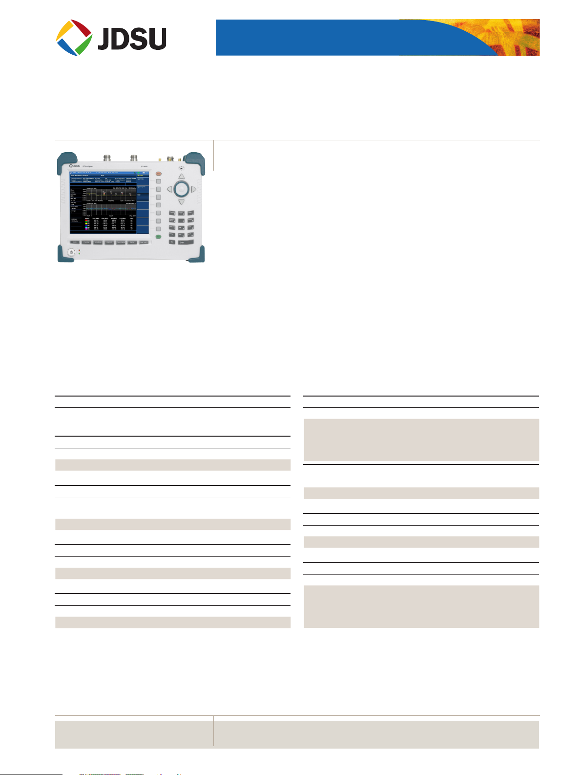
JD746A
CellAdvisor™ RF Analyzer
COMMUNICATIONS TEST & MEASUREMENT SOLUTIONS
Spectrum Analyzer: 100 kHz to 4 GHz
Cable and Antenna Analyzer: 5 MHz to 4 GHz
Power Meter: 10 MHz to 4 GHz
Specication Conditions
e JD746A specications apply under these conditions:
• e instrument has been turned on for at least 15 minutes
• e instrument is operating within a valid calibration period
• Data with no tolerance are considered typical values
• Cable and antenna measurements apply aer calibration to the OSL standard
• Typical and nominal values are dened as:
– Typical: expected performance of the instrument operating under 20 to 30°C
aer being at this temperature for 15 minutes
– Nominal: a general, descriptive term or parameter
Spectrum Analyzer (Standard)
Frequency
Frequency range 100 kHz to 4 GHz
Internal 10 MHz Frequency Reference
Accuracy ±0.05 ppm + aging (0 to 50°C)
Aging ±0.5 ppm/year
Frequency Span
Range 0 Hz (zero span)
10 Hz to 4 GHz
Resolution 1 Hz
Resolution Bandwidth (RBW)
–3 dB bandwidth 1 Hz to 3 MHz 1-3-10 sequence
Accuracy ±10% (nominal)
Video Bandwidth (VBW)
–3 dB bandwidth 1 Hz to 3 MHz 1-3-10 sequence
Accuracy ±10% (nominal)
Single Sideband (SSB) Phase Noise
Fc 1 GHz, RBW 10 kHz, VBW 1 kHz, RMS detector
Carrier oset:
30 kHz
100 kHz
1 MHz
Measurement Range
DANL to +20 dBm
Input attenuator range 0 to 50 dB, 5 dB steps
Maximum Input Level
Average continuous power +20 dBm
DC voltage ±50 VDC
Displayed Average Noise Level (DANL)
1 Hz RBW, 1 Hz VBW, 50 Ω termination, 0 dB attenuation, RMS detector
Preamplier O:
10 MHz to 2.3 GHz
>2.3 GHz to 3 GHz
>3 GHz to 4 GHz
Preamplier On:
10 MHz to 2.3 GHz
>2.3 GHz to 3 GHz
>3 GHz to 4 GHz
<–90 dBc/Hz (typical)
<–95 dBc/Hz (typical)
<–102 dBc/Hz (typical)
–140 dBm (–146 dBm, typical)
–138 dBm (–144 dBm, typical)
–135 dBm (–140 dBm, typical)
–155 dBm (–160 dBm, typical)
–153 dBm (–158 dBm, typical)
–150 dBm (–156 dBm, typical)
WEBSITE: www.jdsu.com/test
Page 2

2
JD746A CELLADVISOR RF ANALYZER
Display Range
Log scale and units
(10 divisions displayed)
Linear scale and units
(10 divisions displayed)
Detectors Normal, positive peak, sample, negative peak,
Number of traces 6
Trace functions Clear/write, maximum hold,
1 to 20 dB/division in 1 dB steps
dBm, dBV, dBmV, dBµV
V, mV, mW, W
RMS
minimum hold, capture, load
view on/o
Total Absolute Amplitude Accuracy
Preamplier o, power level >–50 dBm, auto-coupled (20 to 30°C)
5 MHz to 4 GHz ±1.25 dB, ±0.5 dB (typical)
±1.55 dB, ±1.0 dB (typical)
Attenuation <40 dB
Attenuation ≥40 dB
Reference Level
Setting range –120 to +100 dBm
Setting resolution
Log scale
Linear scale
0.1 dB
1% of reference level
Markers
Marker types Normal, delta, delta pair, noise, frequency count
marker
Number of markers 6
Marker functions Peak, next peak, peak left,
peak right, minimum search
marker to center/start/stop
RF Input VSWR
20 MHz to 4 GHz 1.5:1 (typical)
Second Harmonic Distortion
Mixer level = –25 dBm
10 MHz to 1.3 GHz <–65 dBc (typical)
>1.3 GHz to 4 GHz <–70 dBc (typical)
Dynamic Range
2/3 (TOI-DANL) in 1 Hz RBW >95 dB
Sweep Time
Range 80 ms to 1000 s
24 µs to 200 s
Sweep mode Continuous, single
Span = 0 Hz (zero span)
Gated Sweep
Trigger source External, video, and GPS
Gate length 1 µs to 100 ms
Gate delay 0 to 100 ms
Trigger
Trigger source Free run, video, external
Trigger delay
Range
Resolution
0 to 200 s
6 µs
Measurements*
Channel power
Occupied bandwidth
Spectrum emission mask
Adjacent channel power
Spurious emissions
Field strength
AM/FM audio demodulation
Route map
PIM detect
Dual spectrum
* CW signal generator (Option 003) can be set up simultaneously.
Cable and Antenna Analyzer (Standard)
Frequency
Range 5 MHz to 4 GHz
Resolution 10 kHz
Accuracy ±25 ppm
Third-order Inter-modulation (Third-order Intercept: TOI)
200 MHz to 2 GHz +10 dBm (typical)
>2 GHz to 4 GHz +12 dBm (typical)
Spurious
Inherent residual response
Input terminated, 0 dB attenuation, preamplier o, RBW at 10 kHz
20 MHz to 3 GHz –90 dBm (nominal)
>3 GHz to 4 GHz –85 dBm (nominal)
Exceptions <–80 dBm @ 311.94 MHz
<–84 dBm @ 415.92 MHz
<–85 dBm @ 519.90, 1599.00, and 2497.80 MHz
Input related spurious <–70 dBc (nominal)
Data Points
126, 251, 501, 1001
Measurement speed 1.65 ms/point (nominal)
Measurement Accuracy
Corrected directivity 40 dB (typical)
Reection uncertainty ±(0.3 + |20log (1+10
EP = directivity – measured return loss
Output Power
High 0 dBm (typical)
Low –30 dBm (typical)
-EP/20
)|) (typical)
Page 3

3
JD746A CELLADVISOR RF ANALYZER
Dynamic Range
Reection 60 dB
Maximum Input Level
Average continuous power +25 dBm (nominal)
DC voltage ±50 VDC
Interference immunity
On channel
On frequency
+17 dBm @>1.4 MHz from carrier frequency
(nominal)
0 dBm within ±10 kHz from the carrier frequency (nominal)
Measurements
Reection (VSWR)
VSWR range
Return loss range
Resolution
Distance to Fault (DTF)
Vertical VSWR range
Vertical return loss range
Vertical resolution
Horizontal range
Horizontal resolution
Cable Loss (1-port)
Range
Resolution
1-port Phase
Range
Resolution
Smith Chart
Resolution
1 to 65
0 to 60 dB
0.01
1 to 65
1 to 60 dB
0.01
0 to (# of data points – 1) x Horizontal Resolution
Maximum = 1500 m (4921 ft)
(1.5x10⁸) x (VP) / (delta) x (0.95)
VP = propagation velocity
Delta = stop freq. – start freq. (Hz)
0 to 30 dB
0.01 dB
–180° to +180°
0.01°
0.01
RF Power Meter (Standard)
External RF Power Sensors
Directional Power Sensor JD731B
Frequency range 300 MHz to 3.8 GHz
Dynamic range 0.15 to 150 W (average)
4 to 400 W (peak)
Connector type Type-N female on both ends
Measurement type Forward/reverse average power, forward peak
power, VSWR
Accuracy ±(4% of reading + 0.05 W)
Directional Power Sensor
Frequency range
JD733A
150 MHz to 3.5 GHz
1,2
Dynamic range 0.1 to 50 W (average)
0.1 to 50 W (peak)
Connector type Type-N female on both ends
Measurement type Forward/reverse average power, forward peak
power, VSWR
Accuracy ±(4% of reading + 0.05 W)
1,2
Terminating Power Sensor JD732B
Frequency range 20 MHz to 3.8 GHz
Dynamic range –30 to +20 dBm
Connector type Type-N male
Measurement type Average
Accuracy ±7%
1
Terminating Power Sensor JD734B
Frequency range 20 MHz to 3.8 GHz
Dynamic range –30 to +20 dBm
Connector type Type-N male
Measurement type Peak
Accuracy ±7%
1
Terminating Power Sensor JD736B
Frequency range 20 MHz to 3.8 GHz
Dynamic range –30 to +20 dBm
Connector type Type-N male
Measurement type Average and Peak
Accuracy ±7%
1
General Parameters
Display range –100 to +100 dBm
Oset range 0 to 60 dB
Resolution 0.01 dB or 0.1xW (x = m, u, p)
Internal RF Power Sensor
Frequency range 10 MHz to 4 GHz
Span 100 kHz to 100 MHz
Dynamic range –120 to +20 dBm
Maximum power +20 dBm
Accuracy Same as spectrum analyzer
1. CW condition at 25°C ±10°C
2. Forward power
Optical Power Meter (Option 13)
Optical Power Meter
Display range –100 to +100 dBm
Oset range 0 to 60 dB
Resolution 0.01 dB or 0.1 mW
Page 4

4
External Optical Power Sensors
Optical Power Sensor
Wavelength range
Max permitted input level +10 dBm
Connector input Universal 2.5 and 1.25 mm
Accuracy ±5%
Optical Power Sensor
Wavelength range
Max permitted input level +23 dBm
Connector input Universal 2.5 and 1.25 mm
Accuracy ±5%
2-Port Transmission Measurements (Option 001)
Frequency
Frequency range 5 MHz to 4 GHz
Frequency resolution 10 kHz
Output Power
High 0 dBm (typical)
Low –30 dBm (typical)
MP-60
780 to 1650 nm
MP-80
780 to 1650 nm
JD746A CELLADVISOR RF ANALYZER
CW Signal Generator (Option 003)
Frequency
Frequency range 25 MHz to 4 GHz
Frequency reference ±25 ppm Maximum
Frequency resolution 10 kHz
Output Power
Range 0 dBm, –30 to –80 dBm
Step 1 dB
Accuracy ±1.5 dB (15 to 35°C)
GPS Receiver and Antenna (Option 010)
GPS Indicator
Latitude, longitude, altitude
High-Frequency Accuracy
Spectrum, interference, and signal analyzer
GPS lock ±25 ppb
Hold over (for 3 days) ±50 ppb (0 to 50°C) 15 minutes after satellite
locked
Connector SMA, female
Measurement Speed
Vector 2.2 ms/point (nominal)
Dynamic Range
Vector 5 MHz to 3 GHz, 80 dB
>3 GHz to 4 GHz, 75 dB
Scalar 5 MHz to 4 GHz, >100 dB
Measurements
Insertion Loss/Gain
Range
Resolution
2-Port Phase
Range
Resolution
–120 to 100 dB
0.01 dB
–180 to +180°
0.01°
Bias-Tee (Option 002)
Voltage
Voltage range +12 to +32 V
Voltage resolution 0.1 V
Power
8 W Max
Interference Analyzer (Option 011)
Measurements
Spectrum analyzer Sound indicator, AM/FM audio demodulation, interfere nce ID,
spectrum recorder
Spectrogram Collect up to 72 hours of data
RSSI Collect up to 72 hours of data
Interference nder
Spectrum replayer
Dual spectrogram
Channel Scanner (Option 012)
Frequency Range
10 MHz to 4 GHz
Measurement Range
–110 to +20 dBm
Measurements
Channel scanner 1 to 20 channels
Frequency scanner 1 to 20 frequencies
Custom scanner 1 to 20 channels or frequencies
Wireless Connectivity (Option 006)
Bluetooth Connectivity
Personal Area Networking (PAN)
File Transfer Prole (FTP)
Page 5

5
General Information
JD746A CELLADVISOR RF ANALYZER
Inputs and Outputs
RF in Spectrum analyzer
Connector
Impedance
Damage level
Type-N, female
50 Ω (nominal)
>+40 dBm, ±50 VDC (nominal)
Reection/RF out Cable and antenna analyzer
Connector
Impedance
Damage level
Type-N, female
50 Ω (nominal)
>+37 dBm, ±50 VDC (nominal)
RF in Cable and antenna analyzer
Connector
Impedance
Maximum level
Type-N, female
50 Ω (nominal)
>+25 dBm, ±50 VDC (nominal)
External trigger, GPS
Connector
Impedance
SMA, female
50 Ω (nominal)
External ref
Connector
Impedance
Input frequency
Input range
SMA, female
50 Ω (nominal)
10 MHz, 13 MHz, 15 MHz
–5 to +5 dBm
USB
USB host1
USB client
2
Type A, 1 port
Type B, 1 port
LAN RJ45, 10/100Base-T
GPIO RJ45
Audio jack 3.5 mm headphone jack
External power 5.5 mm barrel connector
Speaker Built-in speaker
Display
Type Resistive touch screen
(as of serial number BEK11791)
Size 8 inch, LED backlight
Resolution 800 x 600
Battery
Type 10.8 V, 7800 mA/hr (Lithium ion)
Operating time >3 hours (typical)
Charge time 2.5 hours (80%), 4 hours (100%)
Charging temperature 0 to 45°C (32 to 113°F) ≤85% RH
Discharging temperature –10 to 60°C (14 to 140°F) ≤85% RH
Storage temperature3 –20 to 50°C (–4 to 122°F)
≤85% RH (noncondensing)
Data Storage
4
Internal
External
5
Minimum 20 MB
Limited by size of USB ash drive
Environmental
Operating temperature
AC Power 0 to 40°C (32 to 104°F) with no derating
Battery 0 to 40°C (32 to 104°F) at charging
–10 to 55°C (14 to 131°F) at discharging
Maximum humidity ≤85% RH (noncondensing)
Shock and vibration MIL-PRF-28800F Class 2
Storage temperature
6
–30 to 71°C (–22 to 160°F)
EMC
EN 61326-2-1 Complies with European EMC
Size and Weight (Standard configuration)
Weight (with battery) <4 kg (8.8 lb)
Size (W x H x D) 295 x 195 x 82 mm
(11.6 x 7.7 x 3.2 in)
Warranty
2 years
Power
External DC input 12 to 19 VDC
Power consumption 32.5 W 45 W maximum
(when charging battery)
Calibration Cycle
1 year
1. Connects flash drive and power sensor
2. Connects to PC for data transfer
3. 20 to 85% RH, store battery pack in low-humidity environment;
extended exposure to temperatures above 45°C could significantly degrade battery
performance and life
4. Up to 700 traces
5. Supports USB 2.0 compatible memory devices
6. With the battery pack removed
Page 6

6
Ordering Information
JD746A CELLADVISOR RF ANALYZER
Standard
Part Number Description
JD746A 100 kHz to 4 GHz spectrum analyzer
5 MHz to 4 GHz cable and antenna analyzer1
10 MHz to 4 GHz RF power meter (internal mode)
Options
NOTE: Upgrade options for the JD746A use the designation JD746AU
before the respective last three-digit option number.
Part Number Description
JD746A001 2-Port Transmission Measurement
JD746A002 Bias-Tee
3
2
JD746A003 CW Signal Generator
JD746A006 Bluetooth connectivity
4
JD746A010 GPS Receiver and Antenna
JD746A011 Interference Analyzer
5, 6
JD746A012 Channel Scanner
JD746A013 Optical Power Meter
7
Standard Accessories
Part Number Description
G710550326 AC/DC power adapter
G710550335 Cross LAN cable (1.5 m)
GC73050515 USB A to B cable (1.8 m)
GC72450518 >1 GB USB memory
G710550325 Rechargeable lithium ion battery
G710550323 Automotive cigarette lighter 12 VDC adapter
G710550316 Stylus
8
8
8
8
8
8
8
JD740A361 JD740A series user’s manual and application software — CD
Optional Calibration Kits
Part Number Description
JD72450509 Y-calibration kit, Type-N(m), DC to 6 GHz, 50 Ω
JD72450510 Y-calibration kit DIN(m), DC to 4 GHz, 50 Ω
JD71050507 Dual-port Type-N calibration kit, 50 Ω
• Y-calibration kit, Type-N(m), DC to 4 GHz, 50 Ω
• Two adapters Type-N(f) to Type-N(f), DC to 4 GHz, 50 Ω
• Two 1 m RF test cables, Type-N(m) to Type-N(m),
DC to 18 GHz, 50 Ω
JD71050508 Dual-Port DIN calibration kit, 50 Ω
• Y-calibration kit DIN(m), DC to 4 GHz, 50 Ω
• Two 1 m RF test cables, Type-N(m) to Type-N(m),
DC to 18 GHz, 50 Ω
• Adapter Type-N(f) to DIN(f ), DC to 4 GHz, 50 Ω
• Adapter Type-N(f) to DIN(m), DC to 4 GHz, 50 Ω
• Adapter DIN(f) to DIN(f ), DC to 4 GHz, 50 Ω
• Adapter DIN(m) to DIN(m), DC to 4 GHz, 50 Ω
Optional RF Cables
Part Number Description
G710050530 1.0 m (3.28 ft) RF cable, DC to 18 GHz, Type-N(m) to Type-N(m), 50 Ω
G710050531 1.5 m (4.92 ft) RF cable, DC to 18 GHz, Type-N(m) to Type-N(f), 50 Ω
G710050532 3.0 m (9.84 ft) RF cable, DC to 18 GHz, Type-N(m) to Type-N(f), 50 Ω
G710050533 1.5 m (4.92 ft) RF cable, DC to 18 GHz, Type-N(m) to SMA(m), 50 Ω
G710050534 1.5 m (4.92 ft) RF cable, DC to 18 GHz, Type-N(m) to QMA(m), 50 Ω
G710050535 1.5 m (4.92 ft) RF cable, DC to 18 GHz, Type-N(m) to SMB(m), 50 Ω
1. Requires calibration kit
2. Requires dual-port calibration kit
3. Requires Option 1
4. Includes a pair of Bluetooth USB dongles with 5 dBi dipole antenna (JD70050006)
5. Highly recommend adding GPS receiver JD746A010
6. Highly recommend adding antennas G70005035x and/or G70005036x
7. Requires optical power sensors MP-60 or MP-80
8. Standard accessory that can be purchased separately
Page 7

7
Ordering Information (cont'd)
JD746A CELLADVISOR RF ANALYZER
Optional Omni Antennas
Part Number Description
G700050351 RF omni antenna Type-N(m), 400 MHz to 450 MHz
G700050352 RF omni antenna Type-N(m), 450 MHz to 500 MHz
G700050353 RF omni antenna Type-N(m), 806 MHz to 896 MHz
G700050354 RF omni antenna Type-N(m), 870 MHz to 960 MHz
G700050355 RF omni antenna Type-N(m), 1.71 GHz to 2.17 GHz
G700050356 RF omni antenna Type-N(m), 720 MHz to 800 MHz
G700050357 RF omni antenna Type-N(m), 2.3 GHz to 2.7 GHz
Optional Yagi Antennas
Part Number Description
G700050364 RF Yagi antenna Type-N(f), 806 MHz to 896 MHz, 10.2 dBd
G700050365 RF Yagi antenna Type-N(f), 866 MHz to 960 MHz, 10.2 dBd
G700050363 RF Yagi antenna Type-N(f), 1.75 GHz to 2.39 GHz, 9.8 dBd
G700050366 RF Yagi antenna SMA(f), 700 MHz to 4 GHz, 1.85 dBd
10
Optional RF Power Sensors
Part Number Description
JD731B Directional Power Sensor (peak and average power)
Frequency: 300 MHz to 3.8 GHz
Power: average 0.15 to 150 W, peak 4 to 400 W
JD733A Directional Power Sensor (peak and average power)
Frequency: 150 MHz to 3.5 GHz
Power: average/peak 0.1 to 50 W
JD732B Terminating Power Sensor (average power)
Frequency: 20 MHz to 3.8 GHz
Power: –30 to +20 dBm
JD734B Terminating Power Sensor (peak power)
Frequency: 20 MHz to 3.8 GHz
Power: –30 to +20 dBm
JD736B Terminating Power Sensor (peak and average power)
Frequency: 20 MHz to 3.8 GHz
Power: –30 to +20 dBm
Optional RF Adapters
Part Number Description
G710050570 Adapter Type-N(f) to Type-N(f), DC to 6 GHz, 50 Ω
G710050571 Adapter Type-N(m) to DIN(f), DC to 4 GHz, 50 Ω
G710050572 Adapter DIN(m) to DIN(m), DC to 4 GHz, 50 Ω
G710050573 Adapter Type-N(m) to SMA(f), DC to 18 GHz, 50 Ω
G710050574 Adapter Type-N(m) to BNC(f), DC to 1.5 GHz, 50 Ω
G710050575 Adapter Type-N(f) to Type-N(f), DC to 4 GHz, 50 Ω
G710050576 Adapter Type-N(m) to DIN(m), DC to 4 GHz, 50 Ω
G710050577 Adapter Type-N(f) to DIN(f ), DC to 4 GHz, 50 Ω
G710050578 Adapter Type-N(f) to DIN(m), DC to 4 GHz, 50 Ω
G710050579 Adapter DIN(f ) to DIN(f), DC to 4 GHz, 50 Ω
9
9
9
Optional Miscellaneous
Part Number Description
G710050581 Attenuator 40 dB, 100 W, DC to 4 GHz (unidirectional)
JD74050341 Soft carrying case
JD71050342 Hard carrying case
JD70050342 Hard carrying case with wheels
JD74050343 Backpack carrying case
G710050585 RF directional coupler, 700 MHz to 4 GHz, 30 dB, input/output;
Type-N(m) to Type-N(f), tap o ; Type-N(f)
G710050586 RF combiner, 700 MHz to 4 GHz, Type-N(f) to Type-N(m)
11
11
G710550324 External battery charger
JD740A362 JD740A series user’s manual – printed version
9. Requires RF cable G710050530
10. Requires RF cable G710050533
11. Highly recommended for LTE testing
Optional Optical Power Sensors
Part Number Description
MP-60 Miniature USB 2.0 Optical Power Sensor
Wavelength range: 780 to 1650 nm
1300, 1310, 1490, 1550 nm: –50 to +10 dBm
850 nm: –45 to +10 dBm
MP-80 Miniature USB 2.0 Optical Power Sensor
Wavelength range: 780 to 1650 nm
1300, 1550 nm: –35 to +23 dBm
980 nm: –30 to +23 dBm
Page 8

JD746A CELLADVISOR RF ANALYZER
Network and Service Enablement Regional Sales
NORTH AMERICA
TOLL FREE: 1 855 ASK-JDSU
1 855 275-5378
Product specifications and descriptions in this document subject to change without notice. © 2013 JDS Uniphase Corporation 30173457 001 0913 JD746ARFA.DS.CPO.TM.AE September 2013
LATIN AMERICA
TEL: +1 954 688-5660
FAX: +1 954 3454668
ASIA PACIFIC
TEL:+852 2892 0990
FAX:+852 2892 0770
EMEA
TEL:+49 7121 86 2222
FAX:+49 7121 86 1222
www.jdsu.com/test
 Loading...