

Page 1
COMMUNICATIONS TEST & MEASUREMENT SOLUTIONS
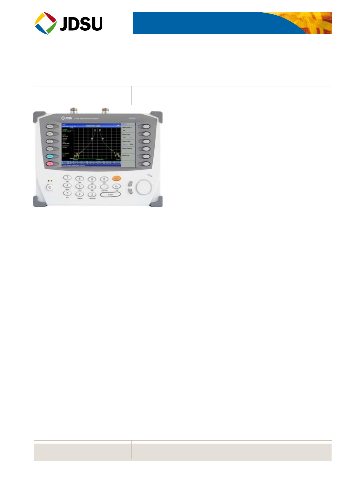
JD725A
Cable and Antenna Analyzer - Dual Port
Key Features
Portable and lightweight handheld instrument•
Built-in wireless frequency bands as well as the most commonly •
used RF cable types
Touch-screen 7” TFT color display •
Superior immunity to RF interferences•
Up to 1001 data points for high resolutions and long distance •
problem location
USB port, allowing external USB memory device•
Saves up to 400 measurement traces•
Saves up to 100 measurement screens•
Saves up to 20 user denable setups•
Interface with application soware, JDViewer, for data •
management and report creation
On-screen keyboard permitting saving les quickly and easily•
Rechargeable and eld replaceable lithium-ion battery•
Key Measurements
VSWR•
Return Loss•
DTF (Distance to Fault)•
Cable Loss•
Insertion Loss •
Insertion Gain•
Power Meter•
RF Source•
Advanced Functions
Trace overlay allows comparative analysis •
of up to 4 traces in a single measurement
screen.
In addition to its 6 markers it also provides •
up to 3 Marker Bands.
Reection measurements are presented in •
VSWR, Return Loss or Smith Charts.
Introduction
Many of modern wireless base stations are a complex system of multiple RF components such as
Low Noise Amplifiers (LNA), duplexers and Tower Mounted amplifiers (TMA). The performance
of those RF components directly affects cell site’s coverage and capacity. It is essential to have the
right instrument to service and verify the proper functionality of those components.
The JD725A has all of necessary measurements functions to perform RF component measurements including, insertion gain, insertion loss, antenna isolation, TMA performance and duplexer
antennas verification.
In addition, the JD725A accurately characterizes the site’s antenna system including Voltage Standing Wave Ratio (VSWR), Distance To Fault (DTF), cable loss and power measurements.
The JD725A is an easy to use field instrument, equipped with a touch panel color display allowing rapid measurements and obtaining results clearly displayed. Its application software, JDViewer,
allows the user to easily compare and analyze measurements and generate professional reports.
The JD725A was designed for field testing operation and is equipped with a rechargeable field
replaceable Lithium-Ion battery which enables continuous operation for more than three hours.
WEBSITE: www.jdsu.com/test
Page 2
2
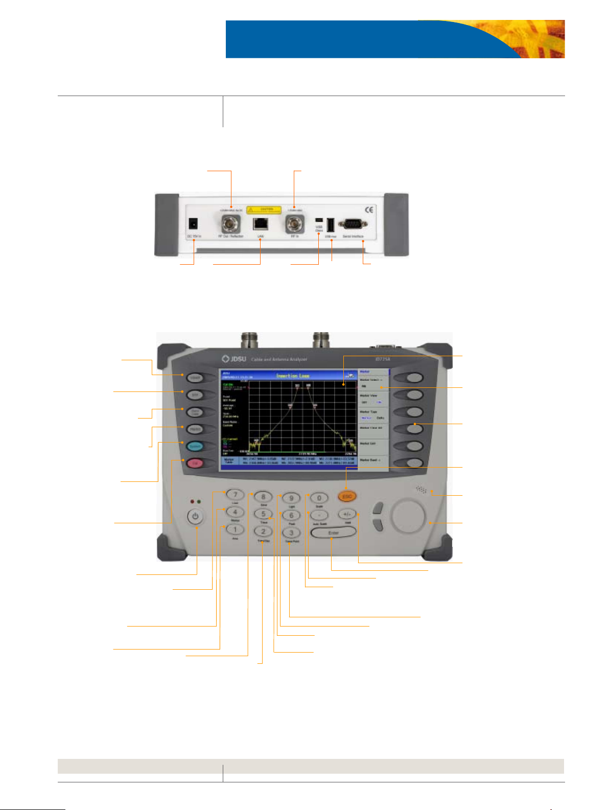
SERIA L
D-sub serial
interface port to
connect an optional
external power
sensor
USB Host
USB Mem ory Stick
port, used for either
saving measurement
data or upgr ading the
instrument’s firmware
LAN
Ethernet
Communication Port
To connect a PC with
the application SW
RF Out/Reflect ion
50ohm N-type RF Connector
to measure VSWR, DTF and
One port cable loss
DC 15V IN
External DC
input port
RF In
50ohm N-type RF Connector, in conjunction with
RF Out/Ref lection port, to measure amplifier
gain and cable insertion loss
USB Client
USB Po rt to
connect a PC with
the application SW
7 “ COLOR LCD
Daylight viewable
high resolution LCD
display
SCRE EN MENU
Displays selectable
menu in connection
with function keys or
sof t ke ys
ESC
Cancels latest
selection or moves
to previous menu
SPEAK ER
Generates audio, if
enabled, for alarms and
key selections
KNOB & UP/DOWN
Mov es marker positions
of items on the table list
ENT ER
Finishes an
“entry”,
wh ich is
value or test
parameter
AUTO SCALE
Adjusts Y scale on
screen for optimal
display of traces
TRACE POINT
Selects trace points among
126, 251, 501 or 1001
TRACE
Captures up to 4 traces
Assign saved trace to T race #
FR EQ / D IST
Sets frequency range or selects a
standard or custom frequency band.
Sets distance and selects standard or
custom cables
MARKER
Supports six ma rke rs
for each tr ace
LOA D
Recalls saved
traces to compare
with current or other
saved traces
POWER & LED
Power ON/OFF
Green LED:
Power On status
Red LED:
External power
CAL
Performs
calibration for
VSWR, DTF,
Cable Loss and
Gain /Loss
measurements
SYSTE M
Pr esent s syst em
information or
upgrades the
instrument's firmware
POWER M ETER and
SIGNAL GENERATOR
Measures transmission
power and generates a
CW signal
GAI N/ LOSS
Measures amplif ier
gain and cable
insertion loss
VSWR
Measures impedance
matching
DTF
Measures distance
to fault location
HOL D
Pauses current
measurement display
SCALE
Changes Y-axis
scal e, VSWR or
Return Loss or
Smith Chart
PEAK
Identifies the highest
peak of the trace
LI GHT
Sets LCD Brightness
AMP
Sets Y-a xis M in /Max,
limit and limit level
SAVE
Save s scr een ,
tr ace, and setup
SOFT KEY
Selects menu
displayed
on the screen
Panel Overview
Top View
Front View
JD725A CABLE AND ANTENNA ANALYZER
Page 3
JD725A CABLE AND ANTENNA ANALYZER
3
Main Functions
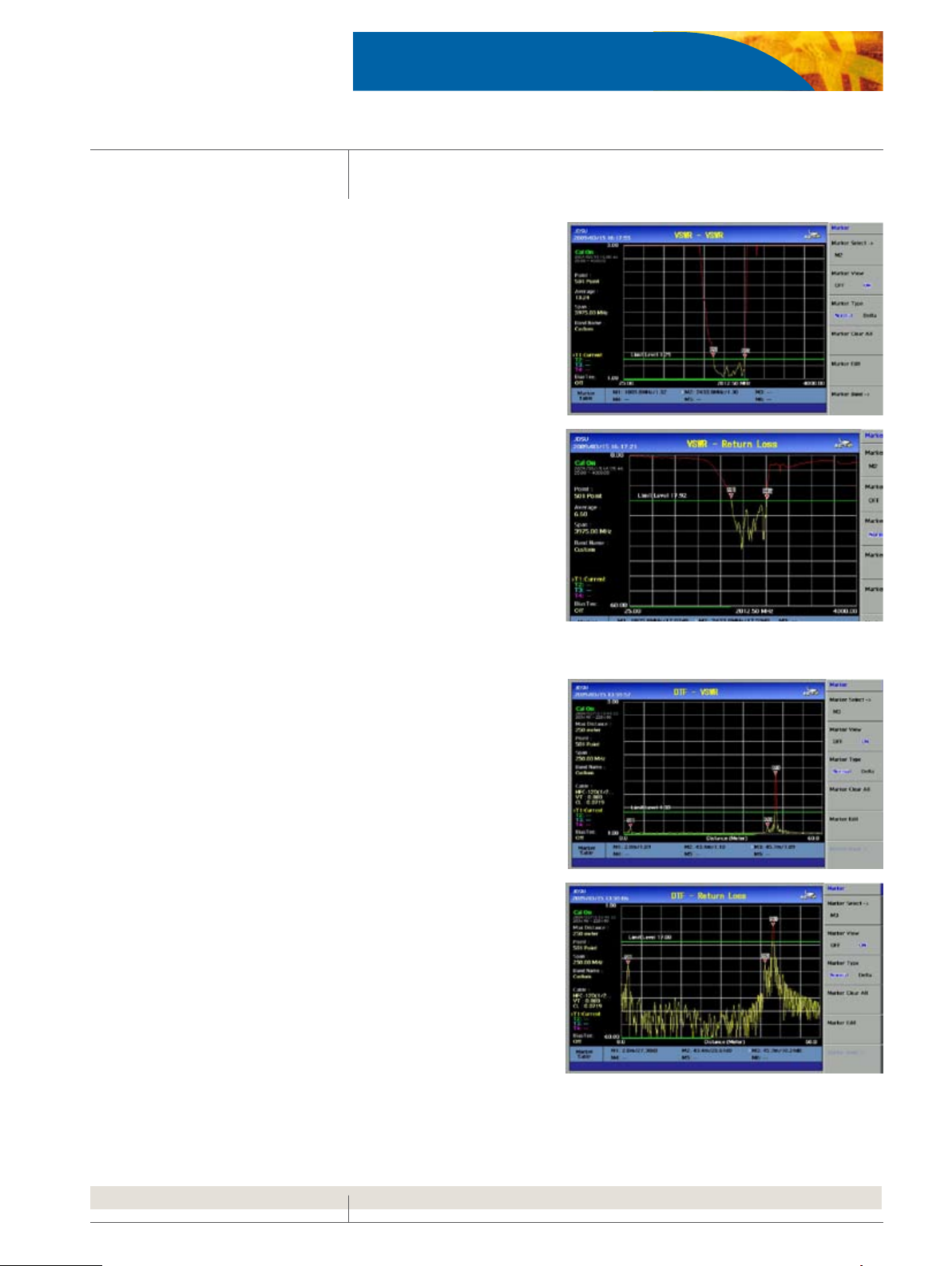
VSWR / Return Loss
VSWR and Return Loss measurements provide the impedance performance and signal reflection characteristics of cable, connectors, and
antenna systems.
Frequency range: 25 to 4000MHz•
Dynamic Range: 60dB•
Over 80 wireless frequency bands built-in in the instrument’s data-•
base
Flexibility to incorporate additional frequency bands•
User denable limit line for•
DTF (Distance to Fault)
The DTF measurement function allows user to accurately identify faulty
locations.
Frequency range: 25 to 4000MHz•
Distance: Up to 1250m (4125)•
Dynamic Range: 60 dB•
High resolution mode with 1001 points•
Over 95 cable types built-in in the instrument’s database•
Flexibility to incorporate additional cable types•
User denable limit line for fast Pass/Fail characterization•
Page 4

JD725A CABLE AND ANTENNA ANALYZER
4
Cable Loss
Cable Loss measures the amount of signal lost by the cable line, this measurement facilitates a rapid compliance verification analysis throughout
the transmission line.
Frequency range: 25 to 4000MHz•
Dynamic Range: 0 to 30dB•
User denable limit line for fast Pass/Fail characterization•
Insertion Gain / Loss
The Insertion Gain measurement simplifies the task of verifying amplifiers and antenna isolation.
Insertion Loss measurements accurately quantifies the amount of signal
loss as it passes through a cable, attenuator, filter, amplifier or any other
RF device.
Frequency range: 25 to 4000MHz•
Dynamic Range: -90 to 50dB•
User denable limit line for fast Pass/Fail characterization•
Page 5

JD725A CABLE AND ANTENNA ANALYZER
5
Power Meter
The Power Meter function makes power measurements easy and comprehensible using external power sensors. Its configurable settings allow
display range, maximum and minimum limits, and the selection of
power units in dBm or Watts.
Lower/Upper power limit can be set for a fast testing through Pass/•
Fail indication
Power Sensor types •
- Directional Power Sensor
- Terminating Power Sensor
Bias Tee (Option JD725A001)
The optional built-in Bias Tee supplies selectable voltage of 12V to 24V
with 3V steps on the RF In port eliminating the need of an external power
supply.
Application Software
The JD725A Application Software, JDViewer, provides all the necessary
tools to operate the instrument more conveniently including:
Communication with the instrument via LAN/USB•
Smith Chart support•
VSWR-DTF conversion•
Captures saved plots •
Registers or edits user denable wireless frequency bands into the •
instrument’s custom bands list
Registers or edits user denable cable types into the instrument’s •
custom cable list
Edits measurement charts•
Report templates available•
Generates and prints reports•
Exports measurement reports•
Page 6

JD725A CABLE AND ANTENNA ANALYZER
6
Advanced Functions
The JD725A provides additional functions allowing superior analysis.
Trace Overlay
Trace Overlay allows comparative analysis of up to 4 traces by superimposing them together on one measurement graph.
Additionally, up to 6 markers can be set on any trace among multiple
traces to see its corresponding value.
Marker Bands
Marker Bands are user definable markers on frequency sub-bands
enabling a visual identification of uplink and downlink frequencies performing compliance verification with a single measurement trace.
Smith Chart
The JD725A is capable of performing Smith Chart measurements to display on the site impedance of the antenna and transmission line.
Page 7

7
Specifications
JD725A CABLE AND ANTENNA ANALYZER
General
Max input power +25 dBm, ± 50 VDC
Frequency range 25 MHz ~ 4000 MHz
Frequency accuracy <± 75 ppm
Frequency resolution 100 kHz
Test port impedance 50 Ω
Test ports Type N Females
Trace storage Up to 400
Screen storage Up to 100
Setup storage Up to 20
Data points 126, 251, 501, 1001
Measurement speed 1, 1.3, 2.5, 5 s for each data point
One port power 6 dBm (typical)
Two port power 6 dBm (typical)
Corrected directivity 40 dB typical
One port accuracy ≤ ±(0.8 +|20 log (1+10
EP = Directivity-measured return loss
Immunity to interference On frequency: +5 dBm
-30 dBm (typical)
-EP/20
)|) dB (typical)
On channel: +17 dBm
VSWR
Range 1 dB ~ 65 dB
Resolution 0.01
Return loss
Range 0 dB ~ 60 dB
Resolution 0.01
DTF
Vertical range VSWR:1 ~ 65
Vertical resolution 0.01
Distance 0 ~ 1250 m (4125 ft)
Horizontal range 0 to (# of data points-1) x horizontal resolution
Horizontal resolution (1.5x10
Vp: cable’s relative propagation velocity
Return Loss 0 dB ~ 60 dB
8
)(Vp)/(Delta)* 0.95
Delta[Hz] = Stop Freq – Start Freq
Cable Loss (one port)
Range 0 dB ~ 30 dB
Resolution 0.01 dB
Insertion Gain/Loss
Range 25 MHz ~ 2500 MHz: -90 ~ 50 dB
Resolution 0.01 dB
2500 MHz ~ 4000 MHz: -80 ~ 50 dB
RF Source
Power output (nominal) Selectable -30 dBm or +6 dBm
Resolution 100 kHz
Bias Tee (optional)
Voltage +12 V ~ +24 V (3 V step)
Current 500 mA steady state (850 mA in rush)
Power Meter (requires optional directional/terminating power
sensor)
Display range -80 dBm ~ +120 dBm
Offset range 0 ~ 60 dB
Resolution 0.01 dB or 0.1 xW
Directional Power Sensors (optional)
JD731A
1)
Sensor type Average and Peak
Frequency range 300 MHz ~ 3800 MHz
Power range Average: 0.15 ~ 150 W (21.76 ~ 51.76 dBm)
Measurement uncertainty ± 4% of reading + 0.05 W
Input return loss ≤ 2500 MHz, 27 dB min
Directivity 27 dB min
Insertion loss < 1 GHz, < 0.05 dB
Connector type N-female on both ends
Peak: 4 ~ 400 W (36.02 ~ 56.02 dBm)
> 2500MHz, 25dB
1 ~ 2 GHz, < 0.1 dB, 2 ~ 3.8 GHz < 0.13 dB
JD733A
Sensor type Average and peak
Frequency range 150 MHz ~ 3500 MHz
Power range Average: 0.25 ~ 20 W (24 ~ 43 dBm)
Measurement uncertainty ± 4% of reading + 0.05 W
Input return loss ≤ 2500 MHz, 27 dB Min
Directivity 27 dB Min
Insertion loss <1 GHz, <0.05 dB
Connector type N-female on both ends
Peak: 0.25 ~ 20 W (24 ~ 43 dBm)
> 2500 MHz, 25 dB Min
1 ~2 GHz, < 0.1 dB, 2 ~ 3.5 GHz < 0.13 dB
Terminating Power Sensors (optional) JD732A, JD734A, JD736A
Sensor type Average (JD732A)
Average and Peak (JD736A)
Frequency range 20 MHz ~ 3800 MHz
Power range -30 ~ +20 dBm (1 µW ~ 100 mW)
Measurement uncertainty ± 7% of reading
Connector type N-male
Peak (JD734A)
JD72450551
Sensor type Average
Frequency range 40 MHz ~ 3000 MHz
Power range ~30 dBm ~ 0 dBm (1 µW ~ 1 mW)
Measurement uncertainty ± 10% of reading
Connector type N-male
2,3
2,3
2,3)
,2,3)
Page 8

JD725A CABLE AND ANTENNA ANALYZER
JD72450552
Sensor type Peak
Frequency range 40 MHz ~ 4000 MHz
Power range ~40 dBm ~ 0 dBm (0.1 µW ~ 1 mW)
Measurement uncertainty ± 10% of reading
Connector type N-male
Miscellaneous
Dimension 260 x 190 x 60 mm (10.2” x 7.5” x 2.4”)
Weight < 2.1 kg (4.62 lbs)
Battery Li-ion (>3hrs continuous operating)
Operating temperature -10 ~ 50 °C (14 ~ 122 °F)
Storage temperature -40 ~ 80 °C (-40 ~ 176 °F)
Humidity 95% no condensation
1) Measurement speed provided at one-port measurements.
2)The specification provided at a temperature of 25°C ± 10°C.
3) CW condition
*All Specifications based on calibrating at 25°C after 5 minute warm-up.
Ordering Information
Mainframe
JD725A Cable and Antenna Analyzer - Dual Port,
25 MHz ~ 4000 MHz
Optional
JD725A001 Bias Tee
Standard Accessories
Soft carring case
AC-DC adapter
Cross LAN cable (1.5 m)
1 GB USB memory
Automotive Cigarette Lighter/12V DC Adapter
Lithium-Ion battery
Stylus pen
User's manual and application software on CD
2 years warranty
Optional Accessories
JD72550507 Dual Port Calibration Kit (N), 40 dB 4 GHz
2,3
GC72450531 RF cable, 1.5 m N(m)-N(f )
GC72450532 RF cable, 3.0 m N(m)-N(f )
JD72350542 Hard case
JD72550562 JD725A User's Manual - printed version
G710050571 Adapter N(m) to DIN(f), DC to 4 GHz, 50 Ω
G710050572 Adapter DIN(m) to DIN(m), DC to 4 GHz, 50 Ω
G710050573 Adapter N(m) to SMA(f), DC to 18 GHz, 50 Ω
G710050574 Adapter N(m) to BNC(f), DC to 1.5 GHz, 50 Ω
G710050581 Attenuator 40 dB, 100 W DC to 4 GHz (unidirectional)
GC7256000 JD725A Warranty extension of 1 year for Asia, North
GC7256001 JD725A Warranty extension of 1 year for Latin
Open-Short-Load, 40 dB, 4 GHz•
Load, 40 dB, 4 GHz•
Two adapters N(f) to N(f ), DC to 4 GHz, 50 Ω•
Two RF test cables (1 m), N(m) to N(m)•
America
America, EMEA
Power Meter Accessories
JD731A Directional power sensor, 300 ~ 3800 MHz,
JD733A Directional power sensor, 150 ~ 3500 MHz,
JD732A Terminating average power sensor
JD734A Terminating peak power sensor,
JD736A Terminating average and peak power sensor,
JD72450551 Terminating average power sensor, 40 ~ 3000 MHz,
JD72450552 Terminating peak power sensor, 40 ~ 4000 MHz,
G710050581 Attenuator 40 dB, 100 W, DC to 4 GHz (unidirectional)
Average 0.15 ~ 150 W, Peak 4 ~ 400W
Average/Peak 0.25 ~ 20 W
20 MHz~ 3800 MHz, -30 ~ +20 dBm
20 ~ 3800 MHz, -30 ~ +20 dBm
20 ~ 3800 MHz, -30 ~ +20 dBm
-30 ~ 0 dBm
-40 ~ 0 dBm
Test & Measurement Regional Sales
NORTH AMERICA
TEL: 1 866 228 3762
FAX: +1 301 353 9216
Product specifications and descriptions in this document subject to change without notice. © 2009 JDS Uniphase Corporation 30149482.002.0609.JD726A.DS.CPO.TM.AE
LATIN AMERICA
TEL: +1 954 688-5660
FAX: +1 954 3454668
ASIA PACIFIC
TEL:+852 2892 0990
FAX:+852 2892 0770
EMEA
TEL:+49 7121 86 2222
FAX:+49 7121 86 1222
www.jdsu.com/test
 Loading...