

Page 1
its 6006
its 6006
Radiated immunity test system 6 GHz
Radiated immunity test system 6 GHz
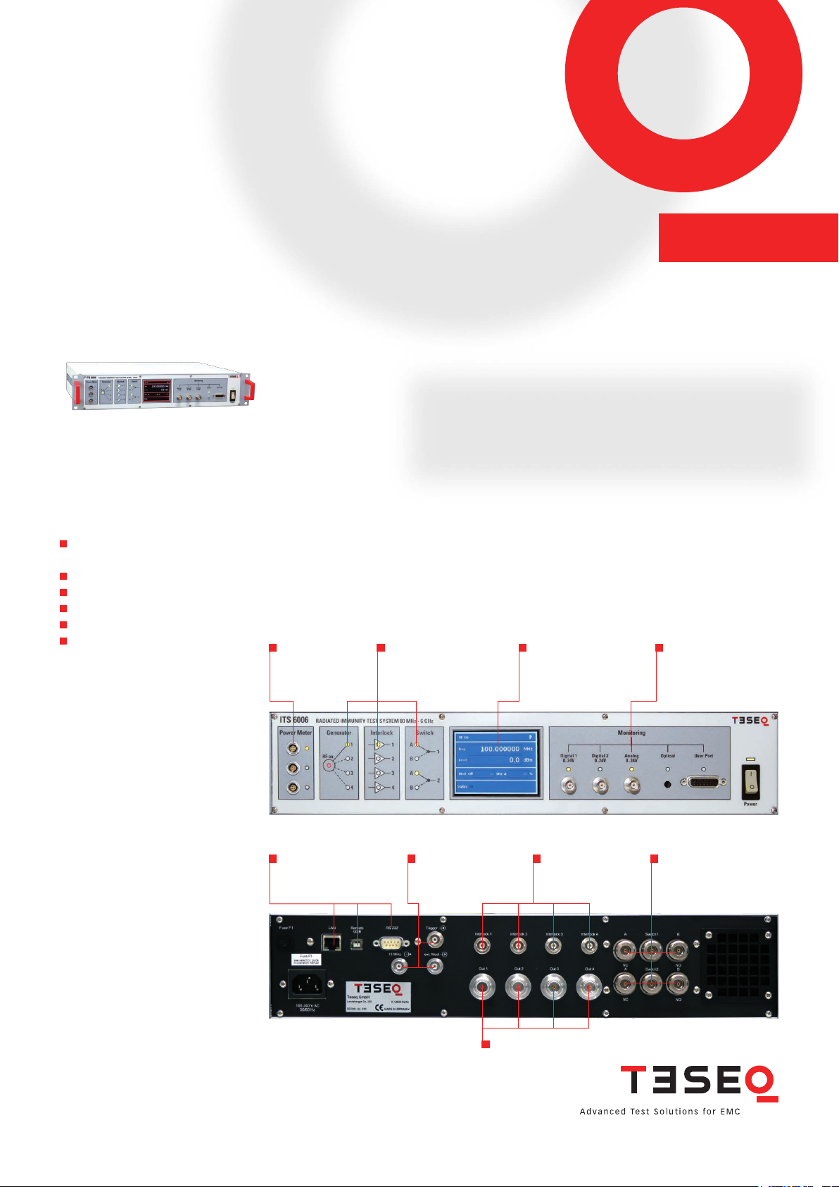
The ITS 6006 consist of an integrated RF signal generator, RF switch and EUT monitoring interfaces.
The unit is designed for various radiated EMC applications in the 80 MHz to 6 GHz frequency range. In
addition to the generator, the system includes the AM and PM modulators necessary for EMC testing.
Other modulators can be connected to the external modulation input of the ITS 6006. The RF signal
ITS 6006
can be switched to one of four outputs, where up to four power ampliers can be connected directly.
Additional RF switches are available for combining two amplier paths into a single antenna connection.
Two of these relays are included for the four amplier paths.
ITS 6006 interlock outputs ensure the activation of the power amplier for only the selected signal path.
The 3.5“color display shows the generator parameters. LEDs indicate the state of further functions.
The EUT monitoring is provided by six digital, one analog and one optical input, as well as four digital
Integrated signal generator 80 MHz
to 6 GHz
Integrated RF switch network
Multiple EUT monitoring options
3.5“ TFT color display
Safet y interlock function
Remote control via USB, RS232 or
LAN
outputs. Up to three power meters PMR 6006 can be connected directly to the ITS 6006. The ITS 6006
provides remote control through its network, RS232 and USB interfaces.
3 power meter
inputs for
PMR 6006
Indicators for RF-switch
network and interlock
functions
3.5“ color display
EUT monitoring ports
and user port for 4 TTL
inputs, 4 TTL outputs
and supply voltages
82-2540 05 E02 March 2011
Remote control via
RS232, LAN or USB
Input s for trig ger,
external modulation,
10 MHz ref out
4 generator outputs
Interlock
RF-switch network with
2x SPDT relays
Page 2
2
ITS 60 06 datasheet
2
Radiated immunity test system 6 GHz
its 6006
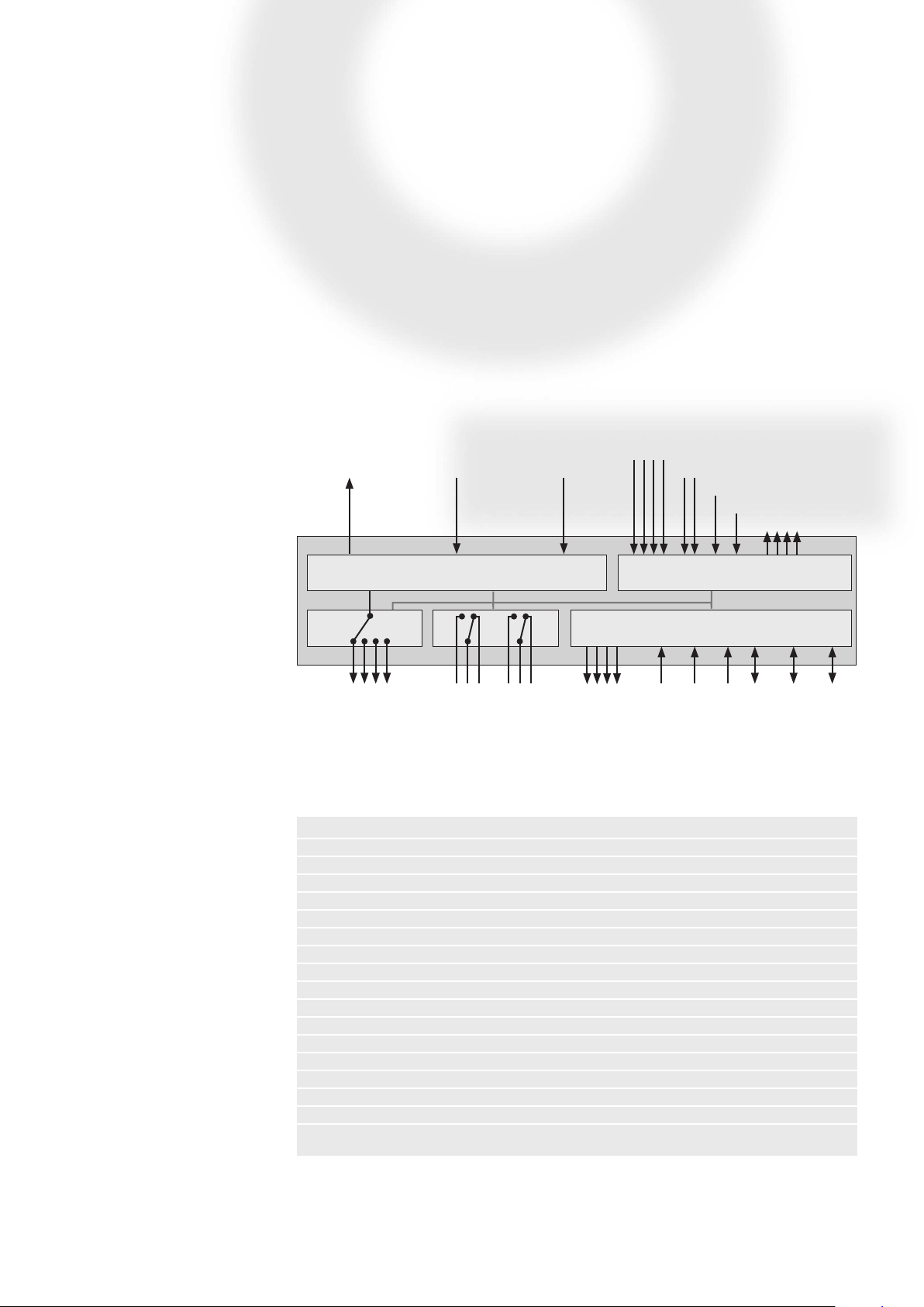
ITS 6006 Block diagram
10 MHz
reference
4 RF outputs 4x Interlock
External
modulation
Signal generator
RF switch
2x SPDT
Trigger
User-Port-IN 0-3
Digital 1 & 2
Optical input
EUT monitoring interface
Control unit
3x PMR 60 06
power meter
Analog input
User-Port-OUT 0-3
Remote control:
LAN, RS232, USB
Technical specifications
Generator
RF
Frequency range: 80 MHz – 6 GHz
Resolution: 1 Hz
Reference frequency: 10 MHz
Max. adjustment deviation: ±50 Hz
Aging: 5 ppm
Level range: -60 dBm to +10 dBm (-60 dBm to +8 dBm at f>3 GHz & ϑ>30°C)
Resolution: 0.1 dB
Accuracy: <1 dB, typ. <0.5 dB (+15 to +25°C)
Spectral distortion
Harmonics (level ≤0 dBm): <-30 dBc, typ. <-35 dBc
Harmonics (level ≤+10 dBm): <-25 dBc
Non harmonics: <-35 dBc
Amplitude modulation
Modulation depth: 0 – 100%
Resolution: 0.5%
Modulation frequency range: 1 Hz – 20 kHz
Frequency resolution: 1 Hz
Page 3

33
Radiated immunity test system 6 GHz
its 6006
82-2540 05 E02 March 2011
Generator (continued)
Pulse modulation
Modulation frequency range: 1 Hz – 2 kHz
Frequency resolution: 1 Hz
Duty cycle: 10% to 90%
External modulation
Level: 1 Vpp to get 100% AM, 1 Hz – 10 kHz
Analog ports
Front panel
Monitoring input analog: BNC socket, 0-24 V Ri=15 kΩ, 6 mV resolution
User port: D-Sub 15 pole
PIN 15: +12 V / max. 200 mA
PIN 14: -12 V / max. 200 mA
PIN 13: +5 V / max. 200 mA
PIN 5 and 10: GND
Back panel
Generator outputs: 4x N sockets 50 Ω, 80 MHz – 6 GHz
Interlock outputs: 4x BNC sockets
External modulation input: BNC socket, impedance >10 kΩ
10 MHz reference output: BNC socket, approx. 0 dBm / 50 Ω
RF Switch network: Relay type 2x SPDT, N sockets 50 Ω
Power up to 100 MHz: 1500 W
Power up to 40 0 MHz: 800 W
Power up to 1 GHz: 50 0 W
Power up to 3 GHz: 300 W
Power up to 6 GHz: 20 0 W
Digital ports
Front panel
Power meter inputs 1 to 3: for connecting up to 3 Teseq PMR 6006
Mo nit oring digital input 1 and 2: BNC socket, 0-24 V vi a optical coupler R i=1.5 kΩ, sw itchin g thres hol d
approx. 2-3 V
Page 4

4
4
its 6006
Radiated immunity test system 6 GHz
Digital ports (continued)
Monitoring optical input: POF (Polymeric optical ber), HP versatile link HFBR0501 series 40
kBd, (avoid scattered light on the front panel)
User port: D-Sub 15 pole, 4 TTL inputs, 4 TTL outputs
Back panel
Trigger input: BNC socket, TTL for external triggering, max. frequency 100 Hz,
trigger delay <50 ms
Remote ports
RS232: D-Sub 9 pole, up to 115200 Bd
USB device connector: connector type “B“
Network: RJ45, Ethernet 10/100 BASE-T
ITS 6006 with 2 amplifiers in a rack
Power supply
Operating range: 100 - 240 VAC, 50 / 60 Hz, autoranging
Power consumption: 90 VA
Fuse: 1.5 A (slow) for 110 V, 1 A (slow) for 230 V
General data
Operating temperature range: 0°C to 40°C
Storage temperature range: -20°C to 60°C
Relative humidity: 95% / 30°C (no moisture condensation)
EMC: DIN/EN 61326-1:2006
Shock: DIN/EN 60068-2-27
Vibration: DIN/EN 60068-2-6
Protection class: DIN/EN 61010-1/IEC 61010-1
Mechanical specifications
Size (W x H x D) : 45 cm (19“) x 10.6 cm (2HU) x 42.3 cm
Weight: approx. 9.5 kg
Cardboard box: 60 cm x 55 cm x 37 cm (additional space for option PMR 60 06
available), weight of cardboard box approx. 2.3 kg (empty)
ITS 60 06 datasheet
Page 5

its 6006
Software
Amp in
Amp out
Amp in
Amp out
EUT monitoring: analog, digital, optical to ITS 6006
Power amplifier 1 and 2
ITS 6006
Switch (part of ITS 6006)
EUT
1
B
A
ITS 6006
Power
RADIATED IMMUNITY TEST SYSTEM 80 MHz - 6 GHz
Power Meter
Generator
4
3
2
1
Interlock
Switch
1
2
A
B
A
B
Analog
0..24 V
Digital 2
0..24 V
Optical
User Port
Monitoring
Digital 1
0..24 V
4
3
2
1
RF on
Generator out 1 to 4
PM channel 1 to 3
2x Switch 1/2
EUT monitoring
DIRECTIONAL COUPLER
Power
Meter
DIRECTIONAL COUPLER
Power
Meter
Software
Amp in
Amp out
Amp in
Amp out
Amp in
Amp out
EUT monitoring: analog, digital, optical to ITS 6006
Power amplifier 1 to 3
ITS 6006
Switch (part of ITS 6006)
EUT
A 2
1
B
B
A
ITS 6006
Power
RADIATED IMMUNITY TEST SYSTEM 80 MHz - 6 GHz
Power Meter
Generator
4
3
2
1
Interlock
Switch
1
2
A
B
A
B
Analog
0..24 V
Digital 2
0..24 V
Optical
User Port
Monitoring
Digital 1
0..24 V
4
3
2
1
RF on
Generator out 1 to 4
PM channel 1 to 3
2x Switch 1/2
EUT monitoring
DIRECTIONAL COUPLER
Power
Meter
DIRECTIONAL COUPLER
Power
Meter
DIRECTIONAL COUPLER
Power
Meter
Radiated immunity test system 6 GHz
Software
The included software allows conguration and application of the ITS 6006 as an signal generator with many additional features like scalar quadripole
measurements for measuring, for example, the insertion loss of the RF cable. For EMC testing, the ITS 6006 can be used in combination with Teseq’s
WIN 6000 or Compliance comprehensive test system software.
Application with 2 power amplifiers and 1 antenna
5
5
Application with 3 power amplifiers and 1 antenna
82-2540 05 E02 March 2011
Page 6

6
ITS 60 06 datasheet
6
Radiated immunity test system 6 GHz
its 6006
Software
Amp in
Amp out
Amp in
Amp out
Amp in
Amp out
Power amplifier 1 to 3
ITS 6006
Switch (part of ITS 6006)
EUT
EUT
1
B
A
ITS 6006
Power
RADIATED IMMUNITY TEST SYSTEM 80 MHz - 6 GHz
Power Meter
Generator
4
3
2
1
Interlock
Switch
1
2
A
B
A
B
Analog
0..24 V
Digital 2
0..24 V
Optical
User Port
Monitoring
Digital 1
0..24 V
4
3
2
1
RF on
Generator out 1 to 4
PM channel 1 to 3
2x Switch 1/2
EUT monitoring
DIRECTIONAL COUPLER
Power
Meter
DIRECTIONAL COUPLER
Power
Meter
DIRECTIONAL COUPLER
Power
Meter
EUT monitoring: analog, digital, optical to ITS 6006
Software
Amp in
Amp out
Amp in
Amp out
Amp in
Amp out
Amp in
Amp out
Switch (part of ITS 6006)Power amplifier 1 to 4
ITS 6006
EUT
EUT
ITS 6006
Power
RADIATED IMMUNITY TEST SYSTEM 80 MHz - 6 GHz
Power Meter
Generator
4
3
2
1
Interlock
Switch
1
2
A
B
A
B
Analog
0..24 V
Digital 2
0..24 V
Optical
User Port
Monitoring
Digital 1
0..24 V
4
3
2
1
RF on
Generator out 1 to 4
PM channel 1 to 3
2x Switch 1/2
EUT monitoring
B 1
A
DIRECTIONAL COUPLER
Power
Meter
B 2
A
DIRECTIONAL COUPLER
Power
Meter
DIRECTIONAL COUPLER
Power
Meter
EUT monitoring: analog, digital, optical to ITS 6006
Application with 3 power amplifiers and 2 antennas
Application with 4 power amplifiers and 2 antennas
Page 7

7
82-2540 05 E02 March 2011
7
Radiated immunity test system 6 GHz
its 6006
B 1
A
Software
Amp in
Amp out
Amp in
Amp out
EUT monitoring: analog, digital, optical to ITS 6006
Power amplifier 1 and 2
ITS 6006
Switch (part of ITS 6006)
Power meter
PMR 6006
A
B
DIRECTIONAL COUPLER
Power
Meter
Power
Meter
GTEM cell
DIRECTIONAL COUPLER
ITS 6006
Power
RADIATED IMMUNITY TEST SYSTEM 80 MHz - 6 GHz
Power Meter
Generator
4
3
2
1
Interlock
Switch
1
2
A
B
A
B
Analog
0..24 V
Digital 2
0..24 V
Optical
User Port
Monitoring
Digital 1
0..24 V
4
3
2
1
RF on
Generator out 1 to 4
PM channel 1 to 3
2x Switch 1/2
EUT monitoring
2
to emission
measuring system
Software
Amp in
Amp out
Amp in
Amp out
Amp in
Amp out
Power amplifier 1 to 3
ITS 6006
Switch (part of ITS 6006)
A 2
1
B
B
A
ITS 6006
Power
RADIATED IMMUNITY TEST SYSTEM 80 MHz - 6 GHz
Power Meter
Generator
4
3
2
1
Interlock
Switch
1
2
A
B
A
B
Analog
0..24 V
Digital 2
0..24 V
Optical
User Port
Monitoring
Digital 1
0..24 V
4
3
2
1
RF on
Generator out 1 to 4
PM channel 1 to 3
2x Switch 1/2
EUT monitoring
DIRECTIONAL COUPLER
Power
Meter
DIRECTIONAL COUPLER
Power
Meter
DIRECTIONAL COUPLER
Power
Meter
EUT monitoring: analog, digital, optical to ITS 6006
GTEM cell
Application with up to 3 GHz with 2 power amplifiers, GTEM cell and connection to the emissions measuring system
Application with 3 power amplifiers and GTEM cell
Page 8

8
8
its 6006
Radiated immunity test system 6 GHz
Model range and options
Part number Description
254005 ITS 6006
Power meter PM 6006, available as
PMR 6006 or PMU 6006
RF-Switch network SW 6012
USO 4013-RS232-20, USB to serial/opti-
cal converter
Immunity test system ITS 6006, 80 MHz to 6 GHz RF generator,
RF switch network, EUT monitoring system, country version EU, UK,
US/JP
97-254005 ITS 6006-TC
Traceable calibration (ISO17025), order only with the device
98-254005 ITS 6006-DKD
DKD calibration (ISO17025), order only with the device
254725 PMR 6006
Power meter PM 6006, 1 MHz to 6 GHz, version R for direct
connection to ITS 6006, cable LE 243-2 included (length 2 m)
254746 PMR 6006-10
Power meter PM 6006, 1 MHz to 6 GHz, version R for direct
connection to ITS 6006, cable LE 243-10 included (length 10 m)
254726 PMU 6006
Power meter PM 6006, 1 MHz to 6 GHz, version USB for
direct connection to PC, cable LE 244 (length 2 m) and storage case
included
97-254725 PM 6006-TC
Traceable calibration (ISO17025), order only with the device
98-254725 PM 6006-DKD
DKD calibration (ISO17025), order only with the device
253892 SW 6012
Option for ITS 6006: RF-Switch network 2x SPDT
254747 USO 4013-RS232-20
Converter USB-to-serial/optical, 20 m POF, optical-to-RS232
254700 IOB 4000
Input/output box, battery operated EUT monitoring system with
op tical int erf ace, in cl. U SO 4 013, 10 m ber o ptical cabl e and storage
case included
253715 WIN 6000
Test house software with 15 months support
For power ampliers, directional couplers and antennas see www.teseq.com.
WIN 6000, Test house software for
using NSG 4070 and ITS 6006
Teseq GmbH
Lands berger Str. 255 · 12623 B erlin · Germany
T + 49 30 56 59 88 35 F + 49 30 56 59 88 34
desales@teseq.com www.teseq.com
ITS 60 06 datasheet
 Loading...