

Page 1
For the very latest specifications visit www.aeroflex.com
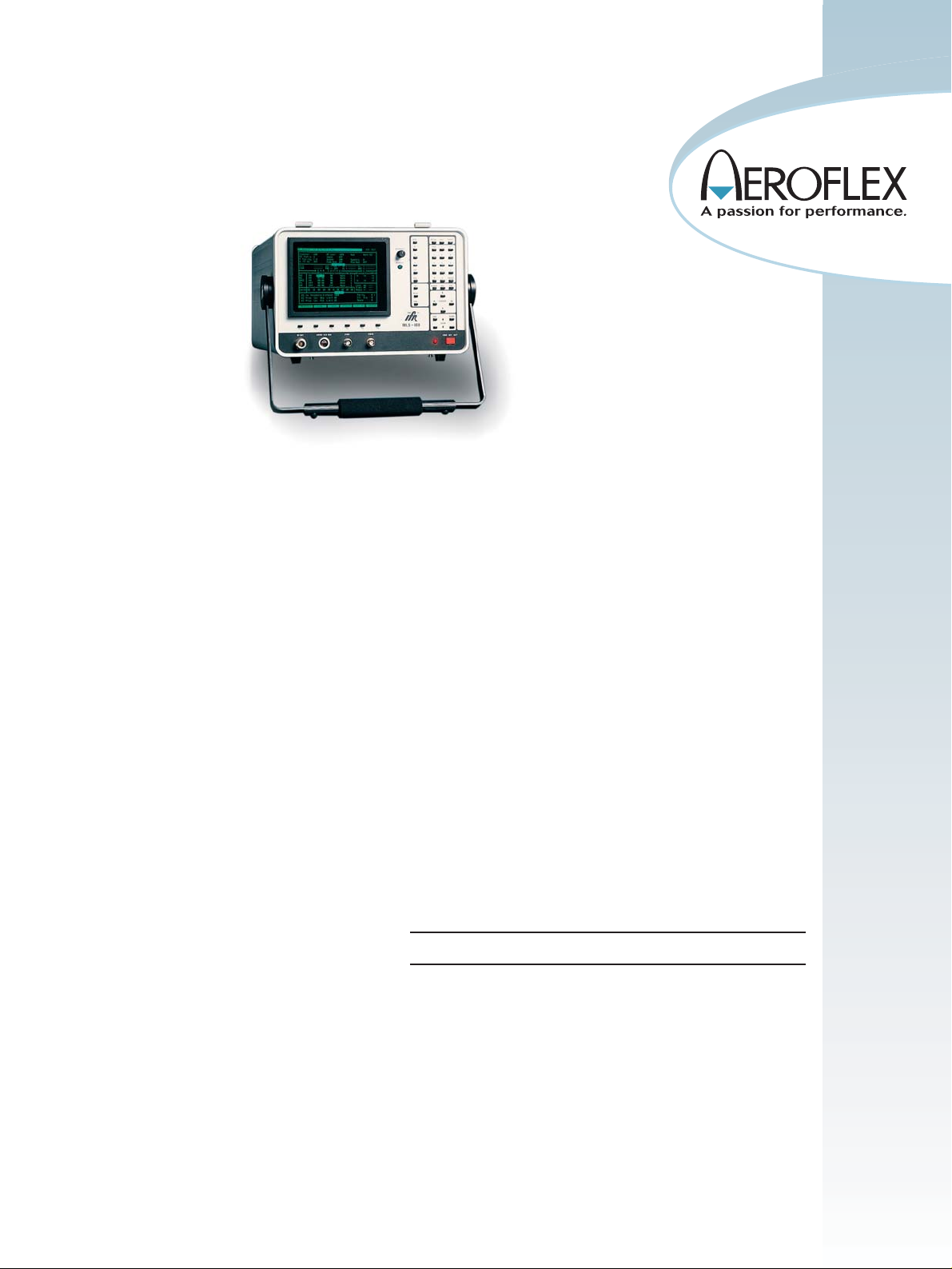
TThhee MMLLSS--880000 pprroovviiddeess ddiiaaggnnoossttiicc tteesstt ccaappaabbiilliittiieess ffoorr mmiiccrroowwaavvee llaannddiinngg ssyysstteemm aannggllee rreecceeiivveerrss..
Avionics
MLS-800 Microprocessor Controlled Ground Station Simulator
• Test Operational Menu supports ICAO
1985 and EUROCAE ED-53A and
ED-36A
• Complete Main Path Simulation:
Approach (AZ) and High Rate Azimuth
(HiAZ) Elevation (EL) Back Azimuth (BAZ)
Flare (FL)
• Complete Multi-path (MP) Simulation
Capability:
Interference Pulses
Selectable Fade Rate Modulation of 0.05,
1 and 1000 Hz
• Control of all Beam Parameters:
Angular Position Beam Amplitude
Referenced to the Preamble Norm and
Half Width Pulse Selectable Beam Width
at 0.5°, 1°, 2°, 3°, 4° or 5°
• Sync Capability for: External Monitoring
Designating PFE and CMN Function
Designating Multi-path Function
• Preamble Parity, Symmetry and Percent
Update
• Simulates all Basic Data Words plus
Auxiliary Data Words with Parity Selection
• Full Range of MLS Channels
Aeroflex is a leader in the design, manufacture
and marketing of Avionics test systems.
The MLS-800 is a microprocessor controlled Ground Station
Simulator designed to operate from a bench test environment. Test
parameters are selected via a 44-position keyboard and displayed on
test operational menus.
Other Features
• OCI Control for Right (RT), Left (LT) and Rear (RR)
• 75 dB AZ to EL Ratio Capability Propellor/Rotor Modulation at 1
to 100 Hz Variable in 1 Hz steps Morse Code Identification
Capability
• ARINC 429 Receiver with PFE and CMN calculations
• External RF Reference Input
• Clearance Pulse Simulation
• 6.75 Hz Modulation
• IEEE-488-1978 Interface for Remote Control Operation
SSPPEECCIIFFIICCAATTIIOONN
GGEENNEERRAALL RREEQQUUIIRREEMMEENNTTSS
• Unless otherwise noted the following equipment performance char-
acteristics are warranted over the specified environmental conditions
following a 20 minute warm-up period.
• All RF measurements are referenced to 50 Ω.
• Accuracy and resolution stated in percent are referenced to measured
or desired values.
• Where resolution exceeds accuracy, resolution takes precedence.
• Notes are intended to provide information useful in applying the
instrument by giving specific setup information. Notes are found in
the notes section of this specification.
Page 2

RRFF SSIIGGNNAALL GGEENNEERRAATTOORR
FREQUENCY
Frequency Range
5031.0 to 5090.7 MHz
Steps
0.3 MHz
Accuracy
±1.0 kHz
OUTPUT POWER
Level Range
-17 to -122 dBm
Level Accuracy
±2.0 dB
Level Flatness
±0.5 dB at -20 dBm (Note 1 and 2)
Attenuator Accuracy
±1.0 dB
Attenuator Monotonicity
±0.5 to 1.5 dB (Each Step)
Spectral Purity
Noise Floor
Offset ± 0.3 to 1.2 MHz from Cf
-105 dBc/Hz (Note 3 and 4)
Residual FM Modulation
<1 kHz peak, 0.01 to 15 kHz BW
Residual Phase Modulation
<0.5 radians peak, 0.3 to 15 kHz BW
Spurious Signal Rejection (in-band)
From ±0.3 to 1.2 MHz
45 dBc
From ±1.2 to 30 MHz (band end)
65 dBc
Spurious Signal Rejection (out of band)
From 5120 to 5250 MHz
50 dBm
From 50 kHz to 12.4 GHz (excluding 5000 to 5250 MHz)
35 dBm
MMOODDUULLAATTIIOONN ((NNoottee 55,, 66 aanndd 77))
MAIN PATH FUNCTIONS
BEAM ANGLES
Azimuth
±62°
High Rate Azimuth
±42°
Elevation
-1.5° to 29.5°
Flare
-2° to 10°
Back Azimuth
±42°
Angle Resolution
±0.05° steps
Angle Accuracy
±0.005°
Basic Data
All functions selectable on menu with selectable data values and parity
Auxiliary Data
All auxiliary data words selectable
BEAM SHAPE
Approximately sinx/x or 1/2 sinx/x waveforms at 1/2 width that fills time
slot. Sidelobes for 1/2 sinx/x are present on pulse side only.
BEAM WIDTH
Selectable to 0.5°, 1°, 2°, 3°, 4°, 5°
Accuracy
±10% of setting
Beam Level
Adjustable relative to preamble
Range
-3.0 to +13.0 dB (Note 6)
Resolution
1.0 dB steps
Accuracy
±1.0 dB
Side Lobes
Relative to beam level
Level
-20.0 dB, ±1.0 dB
OCI Pulses (Right, Left, Rear)
Width
100 ms, ±10 ms
Level
Adjustable relative to preamble
Range
-4.0 to +7.0 dB
RESOLUTION
1.0 dB steps
ACCURACY
±1.0 dB
DPSK MODULATION
Phase Shift
Logic Zero (0)
No transition
Logic One (1)
180°, ±10°
Amplitude Balance
±0.4 dB
TRANSITION TIME
<10
µ
s, 10% to 90%
MULTI-PATH FUNCTION
ANGLE
Selectable to maximum angle for selected function
ANGLE RESOLUTION
0.05° steps
ANGLE ACCURACY
±0.05°
BEAM SHAPE
Approximately sinx/x or 1/2 sinx/x waveforms at 1/2 width that fills time
slot. Sidelobes for 1/2 sinx/x are present on pulse side only.
BEAM WIDTH
Selectable to 0.5°, 1°, 2°, 3°, 4°, 5°
Page 3

For the very latest specifications visit www.aeroflex.com
Accuracy
±10% of setting
Beam Level
Adjustable relative to preamble (Note 6, 8 and 10)
Range
-14.0 to +13.0 dB
Resolution
1.0 dB steps
Accuracy
±1.0 dB, -3.0 to +13.0 dB
±2.0 dB, -14.0 to -4.0 dB
SIDE LOBES
Relative to beam level
Level
-20.0 dB, ±1.0 dB
Main Path to Multi-path
±1.0 dB tracking error
FADE RATE
Frequency Range
Selectable 0.05, 1 and 1000 Hz
Accuracy
±1.0 %
Steps
Eight discrete steps that approximate a sine wave
Clearance Pulses (Note 9)
Position
Two pulses spaced equidistant from 0.0°
Angle Resolution
±0.05°
Angle Accuracy
±0.05°
Pulse Width
50.0
µ
s, ±5.0 µs
AMPLITUDE
Range
-3.0 to +13.0 dB
Resolution
1.0 dB steps
Accuracy
±1.0 dB
AADDDDIITTIIOONNAALL FFUUNNCCTTIIOONNSS
AZ to EL RATIO
Selectable so Azimuth to Elevation function ratio is 0 or -75 dB
Accuracy
±2 dB
Interference Modulation
Propeller Modulation
Frequency
Variable 1 to 199 Hz
Resolution
1.0 Hz steps
Accuracy
±1%
Duty Cycle
-12 dB, ±2 dB applied for 15%, ±1%
Sync
Not in sync with any function
6.75 HZ MODULATION
Frequency
6.75 Hz
Accuracy
±1%
Level
Selectable ±6.0 dB square wave modulation to main beam (Note 6
and 10)
Accuracy
±1.0 dB
Sync
Not in sync with any function
MORSE CODE
Selection
Off, selectable or Continuous Tone
OSCILLOSCOPE SYNC
Selection
Selectable to occur at start of any function, basic or auxiliary data
word
Amplitude
Positive TTL pulse approximately 14
µ
s wide.
Note: Sync control specifies to which function or data word the tests
in Table 1 apply.
FUNCTION APPLICATION
P PARITY CONTROLS PREAMBLE PARITY
6.75 Hz ENABLES OR DISABLES 6.75 Hz MODULATION
UPDATE CONTROLS % UPDATE RATE
FADE RATE CONTROLS FADE RATE (APPLIED TO MULTI-PATH
BEAM)
SYMMETRY CONTROLS BEAM SYMMETRY
PROP MOD CONTROLS PROPELLER MODULATION
FREQUENCY
PFE MEASUREMENT OF PATH FOLLOWING ERROR
CMN MEASUREMENT OF CONTROL MOTION NOISE
Table 1 - Oscilloscope Sync
FUNCTION UPDATE RATE
Selection
100%, 75%, 55%, 45%, 25% and 0%
Accuracy
±3.9 %
FUNCTION UPDATE RATE AVERAGE RATE OVER 10
SECONDS
AZ 100 % 13.0 ±0.5 Hz
HiAZ 100 % 39.0 ±1.5 Hz
BAZ 100 % 6.5 ±0.25 Hz
EL 100 % 39.0 ±1.5 Hz
FUNCTION PREAMBLE PARITY
Selection
Function identified by Oscilloscope Sync selection is candidate to have
its parity bits individually inverted to provide a change in parity.
SCANNING BEAM TIME SYMMETRY
Selection
0 (OFF), ±60
µ
s in 1 µs steps referenced to proper timing from pre-
Page 4

Part No. 46891/139, Issue 6, 08/06
CHINA Beijing
Tel: [+86] (10) 6539 1166
Fax: [+86] (10) 6539 1778
CHINA Shanghai
Tel: [+86] (21) 5109 5128
Fax: [+86] (21) 5150 6112
FINLAND
Tel: [+358] (9) 2709 5541
Fax: [+358] (9) 804 2441
FRANCE
Tel: [+33] 1 60 79 96 00
Fax: [+33] 1 60 77 69 22
GERMANY
Tel: [+49] 8131 2926-0
Fax: [+49] 8131 2926-130
HONG KONG
Tel: [+852] 2832 7988
Fax: [+852] 2834 5364
INDIA
Tel: [+91] 80 5115 4501
Fax: [+91] 80 5115 4502
KOREA
Tel: [+82] (2) 3424 2719
Fax: [+82] (2) 3424 8620
SCANDINAVIA
Tel: [+45] 9614 0045
Fax: [+45] 9614 0047
SPAIN
Tel: [+34] (91) 640 11 34
Fax: [+34] (91) 640 06 40
UK Burnham
Tel: [+44] (0) 1628 604455
Fax: [+44] (0) 1628 662017
UK Cambridge
Tel: [+44] (0) 1763 262277
Fax: [+44] (0) 1763 285353
UK Stevenage
Tel: [+44] (0) 1438 742200
Fax: [+44] (0) 1438 727601
Freephone: 0800 282388
USA
Tel: [+1] (316) 522 4981
Fax: [+1] (316) 522 1360
Toll Free: 800 835 2352
www.aeroflex.com
info-test@aeroflex.com
As we are always seeking to improve our products,
the information in this document gives only a general
indication of the product capacity, performance and
suitability, none of which shall form part of any contract. We reserve the right to make design changes
without notice. All trademarks are acknowledged.
Parent company Aeroflex, Inc. ©Aeroflex 2006.
Our passion for performance is defined by three
attributes represented by these three icons:
solution-minded, performance-driven and customer-focused.
amble Receiver Time Reference Code
External Reference Input
Variable 9.999940 to 10.000060 MHz at 3.0 dBm nominal
AARRIINNCC 442299 RREECCEEIIVVEERR
Rates
12.5 and 100 kbps data rates
Format
Return to Zero (RZ)
Levels
Logic "1" = +5 to 10 V input, typical
Logic "0" = -5 to -10 V input, typical
Transitions
Rise and fall times <1.5
µ
s
GGPPIIBB
Conforms to IEEE-488-1978 Standard for Talker/Listener
PPOOWWEERR
AC
Voltage
103.5 to 240 VAC
Frequency
45.0 to 440 Hz
Power Consumption
85.0 W, maximum
Fuse Requirements
2.5 A, 250 V, Type F
DC
Voltage
11.0 to 30.0 VDC
Fuse Requirements
7.5 A, 32 V min., Type F
BATTERY
Time Out
10 minute time out circuit to prevent accidental discharge. Low voltage
detect turns unit off prior to performance being affected.
Charge Cycle
At least 3 cycles or 30 minutes of charge life before recharge
EENNVVIIRROONNMMEENNTTAALL
Weight
22.7 kg (50 lbs.) Maximum
Dimension (with lid)
234.9 mm high x 539.75 mm deep x 355.6 mm wide
9.25 in. high x 21.25 in. deep x 14.0 in. wide
Operating Temperature
+10° C to +40° C
Storage Temperature
-40° C to +71° C
RREEFFEERREENNCCEE NNOOTTEESS
Note 1: Measured with 1000 Hz Fade Rate applied to Multi-path with
Multi-path OFF, 14 dB Pad applied, and Main Path in CW, 0
dB modulation
Note 2: 0.2 to 0.4 dB variation in level at Fade Rate is normal opera-
tion and is due to residual component of Multi-path signal.
0.8 dB variation is normal for Multi-path signal at Multi-path
= 0 dB, Main Path = OFF.
Note 3: -105 dBc/Hz is approximately equal to -60 dBc in a 30 kHz
bandwidth.
Note 4: Total spurious power should not exceed -15 dBc or -35 dBm
at -20 dBm level setting from 50.0 kHz to 12.4 GHz.
Note 5: Angular range is limited to slightly less than maximum range
for beam widths of 0.5° and 1.0° according to following table:
FUNCTION RANGE 0.5° RANGE 1.0°
AZ -61° to 61° -61.95° to 61.95°
EL -1.0° to 29.5° -1.0° to 29.5°
BAZ -41.75° to 41.75° -41.75° to 41.75°
FL -1° to 9° -1° to 9°
HiAZ -41° to 41° -41.95° to 41.95°
Note 6: RF preamble level plus modulation level should not exceed - -
10.0 dBm.
Note 7: Beam modulation level of +6 dB above preamble is assumed
unless specified.
Note 8: When clearance is selected, each pulse is individually selec-
table in amplitude.
Note 9: Selectable for AZ, HiAZ and BAZ functions only. Angular range
is ±1° to ±61° for AZ and ±41° for HiAZ and BAZ.
Note 10: Combined modulation level in a given time slot not to
exceed +15 dB relative to preamble. Includes main path and multipath +6.75 Hz modulation.
 Loading...