

Page 1
The Model 39 Power Meter and 41B
Harmonics Analyzer combine the ease of
use of a digital multimeter, the visual
feedback of an oscilloscope and the
power of a harmonics analyzer in a
single instrument. If you're testing power
on three-phase systems or troubleshooting harmonics on non-linear loads,
no test tool makes it easier.
The Model 41B is ideal for further
analyzing data and optimizing system
performance. Use the Model
FlukeView
software (included) to
41B'$
download acquired data to a printer or
an MS-DOS
or Windows
compatible
computer for analysis and presentation.
Three Views of each reading:
• Waveform
• Bargraph showing harmonic levels
Numeric values
a Real-time display updates. Display
updates three times per second,
providing a dynamic view of actual
circuit conditions
Comprehensive measurements.
Measure rms, peak and total harmonic
distortion (THD( for complex voltages
and currents - with no manual
calculations required.
„a
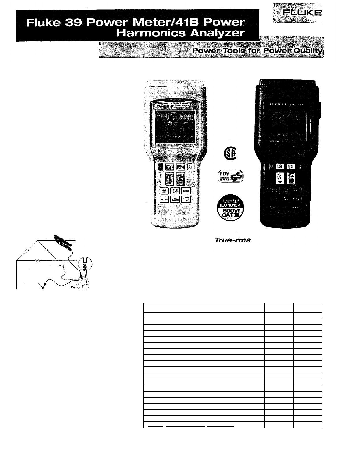
Three-Phase readings
From a simple single-phase
measurement, automatically calculates
three-phase power and power factor
for three-wire balanced loads,
System Critical Data Immediate
readings of Power Factors, KVAR,
Crest Factor, K-Factor
• Display Harmonics individually to
the 31 st
• Min/Max and Average recording
• Data Storage of up to eight complete
measurement sets (Fluke 41B)
*On-line Data Logging with connection to
laptop computer (Fluke 41B(
Safety Conformance
Independently tested and approved
for CSA C22.2 No. 1010-1, TUV to
EN61010 and UL3111 listing. Protected
to IEC 61010-1 Category III 600V
Features
Direct 30 power readouts from simple single-phase measurement
True-rms voltage from 5.OV
True-rms current from 1A
Peak, DC. and Crest Factor
Total harmonic distortion (%THDF and %THDR)
Active power from IOW to 3OOkW (6OOkW
Apparent power (VA) & Reactive Power (VAR)
Total Power factor (PF)
Displacement Power Factor (DPF)
K-factor
Frequency from 6Hz - 99.9Hz(fundamental)
Harmonics to 31st
Phase angle of fundamental and harmonics
Waveform,
text and spectrum displays
Record mode - MIN. MAX and AVG
Zoom mode on harmonics bargraphs
Memory for 8 complete data sets
Data Logging
Optically isolated RS-232 interface
FfukeView
PC software for Windows
to 600V
to SODA (1000A
with optional probe}
with optional probe}
and DOS included
i
46
0
Page 2
Fluke 39 Power
Applications
VOLTS
Display
One cycle of
the fundamental
waveform and
its
frequency.
Instantaneous voltage at cursor position.
Application
Detecting flat-topped voltage caused by
current harmonics, and notching caused
by SCR switching.
AMPS
Display
%-
fundamental
%-rms, rms value,
frequency, and phase
angle of fundamental
or harmonic currents (up to 31st(,
as selected by cursor from bar graph.
Application
Identifying .sources of harmonic currents.
Obtaining data for designing, specifying
or sizing transformers, filters, etc.
WATTS
Display
Watts, volt-amps,
power factor (total)
and displacement
power factor (COS 0)
of single or three-phase power.
Application
Identifying displacement (COS
total power factor. Determining proper
power-factor correction methods.
Using the
included
PlukeView
418 software
you can
upload and
download
measurements
and setups to
a Windows or DOS based PC.
or
i
.
0)
versus
Meter/4113
Harmonics
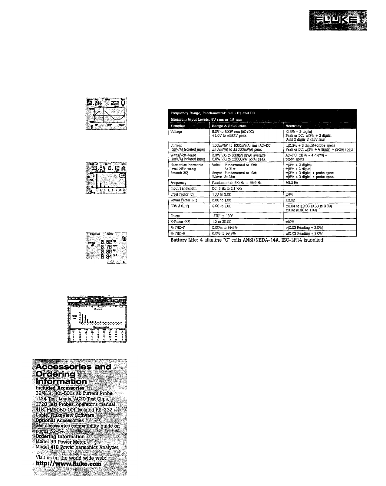
48 hours typical (continuous)
Shock & Vibration: Per MIL-T-28800, Class 3
Case: Drip-Proof and Dust-Proof per IEC, IP 52
Size: 234 mm L x 100 mm W x 134 mm D
Weight: 0.9 kg
One-Year Warranty
39/41B Power Meter Glossary:
DPF
Displacement Power Factor (COS 0). DPF is used to measure the effect o€ inductive
(
motor, transformer( and capacitive loads on the efficiency of an ac distribution system. Such loads
have a reactive component (see VARs) which must be taken into account when sizing system
capacity, but they are still linear loads (current is drawn as a sine wave). DPF therefore does not
include the effect of non-linear harmonic currents, However, a low
demand charges by utilities.
PF
Power Factor or Total Power Factor. Active Power divided by Apparent Power. PF is a
measurement of the efficiency of an ac power transmission and distribution system, including the
effects of harmonics (as well as VARs). Harmonic currents cause PF to be lower than DPF.
%
THD-F
represents the ratio of the harmonic components of voltage lot current) to the voltage (or current)
of the fundamental alone. All measurements are true-rms.
O/oTHD-R
ratio of the harmonic components of voltage (or current) to the total voltage (or current), including
the fundamental and all harmonics. All measurements are true-rns.
(
k)W
electrical power which does work, which by definition includes heat losses. Utility charges are
based on Watts.
(
k)VA
values of voltage and current, It is a measure of the total electrical power capacity of a distribution
system or component equipment. In addition to Watts, it includes the contributions of VARs and
harmonic currents. This term is of interest because utility and facility engineers must size their
system equipment in VA, in effect providing the current-carrying capacity to handle the worstcase situation.
(k)
(
Apparent Power), caused by a phase shift between ac current and voltage in inductors (coils) and
capacitors. In inductors, current lags voltage (in time), while in capacitors, current leads voltage.
VARs are typically first present in a distribution system as a result of inductive loads such as
motors, reactors and transformers. VARs are then used in sizing power factor correction
capacitors, which are used to offset the effects of these inductive loads.
Percent Total Harmonic Distortion-Fundamental reference. This reading
Percent Total Harmonic Distortion-HMS reference. This reading represents the
(
kilo)
Watts. Active power, also known as Real/True Power. Watts measure that portion of
(
kilo) Volt-Amperes. Apparent power. VA is computed by taking the product of the rms
VAR
(
kilo) Volt-Amps Reactive. Reactive Power. VARs are the reactive component of VA
Power
Analyzer
DPF
will often result in extra
 Loading...