

Page 1

2680 Series
Data Acquisition Systems
Technical Data
The Fluke 2680A Data Acquisition
System and Fluke 2686A Data Logging System (the 2680 Series) are
the newest in a long line of Fluke
precision data acquisition products.
Both systems feature:
•
120-channel capacity chassis
designed for small- and largescale precision data acquisition
applications.
•
User-scalability from 20 to 120
universal analog input channels;
can include digital input/output
and alarm contact outputs in a
single chassis.
•
Ethernet TCP/IP protocol
with network interface for
10/100 BaseT.
•
Powerful HMI development
software and OPC server
software available.
Key system features:
•
20 to 120 universal analog inputs per chassis; systems to +2,000
channels
•
Stand-alone data logger operation with the 2686A
•
Large scalable LAN systems using the 2680A with
10BaseT/100BaseT
•
Two types of Universal Input Modules: high-isolation precision
modules or fast scan modules, with 16- to 18-bit resolution
•
Throughput of more than 3,000 channels per-second per chassis
with 2680A-FAI modules
•
Superior thermocouple measurement accuracy (J, K, R, S, T, N, L, U,
C, B)
•
20 digital I/O and 8 form C, 1 Amp relay output modules for direct
control of equipment
•
Up to 300V input isolation, 1600V transient overvoltage protection
(2680A-PAI)
•
Universal input conditioning for any input, on any channel, in any
combination (Vdc, Vac, Ohms, frequency, RTD, thermocouple,
thermistor or current)
•
ATA flash memory card for stand-alone operation—from 16 MB to
1 GB (2686A only)
•
Multiple power sources: 100 to 240 V and 9 V to 45 V dc
•
Includes Fluke DAQ Software which:
•
Controls all 2680 Series functions and data files
•
Provides real-time and historical trending
•
Also communicates with and controls Fluke 2640A,
2645A NetDAQ products
Fluke 2680 Series:
A powerful choice
The Fluke 2680 Series offers the
choice of networked data acquisition, stand-alone data logging, or a
combination of both. Choose from
two basic chassis models:
2680A Data Acquisition
System chassis
The Fluke 2680A Data Acquisition
System is the choice for multichannel applications requiring reliable Ethernet communications. It
features a front-end style data
acquisition system that communicates and distributes data anywhere you need it to go. The
10BaseT and 100BaseT communications interface makes it compatible with both older and newer
network installations.
2686A Data Logging
System chassis
The Fluke 2686A Data Logging
System writes data to a memory
card for easy retrieval and storage,
making it ideal for remote locations
and mobile or non-computer
assisted data logging applications.
Page 2
2686A Active Channels and Memory Card Capacity (Scans)
Memory Card/
Active Channels 20 ch 40 ch 60 ch 80 ch 100 ch 120 ch
16 MB 100,548 66,765 50,074 40,059 33,382 28,613
128 M B 800,000 528,000 400,000 320,000 264,000 224,000
256 MB 1.6 M 1.056 M 800,000 640,000 528,000 448,000
512 MB 3.2 M 2.112 M 1.6 M 1.28 M 1.056 M 896,000
1 GB 6.2 M 4.224 M 3.2 M 2.56 M 2.112 M 1.792 M
2 Fluke Corporation 2680A Series Data Acquisition Systems
2680A-FAI: The speed to
capture dynamic process
changes
The Fluke 2680A-FAI (Fast Analog
Input) is a perfect choice when you
need a lot of information in a hurry
and still need to maintain a high
degree of accuracy for your measurements. The 2680A-FAI module
provides chassis throughput rates
of more than 3,000 channels-persecond. Specially manufactured
field effect transistors (FETs) allow
up to ± 50 V input, and channelto-channel isolation well above
the 15 V industry norm, to give
you more confidence in the
integrity of your measurements.
The system comes with a 16 MB
ATA
memory card, and supports ATA
flash memory cards of up to 1 GB to
provide the memory capacity
you
need. The 2686A is easily configured for stand-alone data logging
operations by simply selecting a
preset configuration from the memory card. It can also be used in networks in tandem with the 2680A
to provide the extra data security of
a memory card.
Scale your system to meet
your needs
With the Fluke 2680A and the
2686A, you can seamlessly expand
your system from 20 to more than
2,000 channels just by adding
modules and chassis. Both models
feature six slots in each chassis
that you can fill with modules as
needed to meet your application
requirements. Five slots in each
chassis are available for any combination of 20-channel analog
input modules available for the
2680 Series. The sixth slot is also
available for a digital I/O relay
module to add control capabilities
to your system. If you don’t need
the sixth slot for control, you can
plug in an additional analog input
module, increasing your input
channel count to 120 in one chassis.
You can also link multiple 120channel systems together seamlessly for the widest possible view
of your data. And, with TCP/IP
connectivity, you can connect to
existing LANs to distribute information wherever it needs to go.
Whether you need speed and
throughput, isolated precision, or
digital I/O and relays, the Fluke
2680 Series can scale up to thousands of channels to meet your
needs. Buy just the modules you
need in the combinations you need
and expand your system as your
requirements grow.
2680A-PAI provides high
precision and high isolation
for the most demanding jobs
The Fluke 2680A-PAI (Precision
Analog Input) 20-channel highprecision, high-isolation module
serves the most demanding jobs
where precision is paramount and
isolation is critical. Some of the
most notable applications for this
module include temperature measurement in semiconductor and
pharmaceutical manufacturing, as
well as nuclear plant performance
monitoring. The 2680A-PAI
module offers 300 V of isolation
on two channels and 150 V on 18
channels, as well as 18-bit resolution and excellent thermocouple
accuracy, all in a scalable system.
Both the 2680A-FAI and the
2680-PAI modules support a wide
range of inputs including dc volts,
ac volts, RTD, Ohms, thermocouple,
thermistor, dc current, ac current,
and frequency. Other sensors and
transducers, such as load cells,
pressure sensors, and displacement sensors can be easily incorporated into your measurement
system.
Analog Input Modules
Page 3

2680A Series Data Acquisition Systems Fluke Corporation 3
2680A-DIO: Digital I/O and
relay outputs add control
For data acquisition systems that
also require control functionality,
the Fluke 2680A-DIO digital I/O
and relay output module provides
20 digital I/O and eight hard-contact 1 Amp form-C relays. This
equips each chassis to respond to
a wide range of alarm or control
situations. The 2680A-DIO also
includes an up/down counter with
preset start count capability, so
you don’t need to begin all counts
at zero.
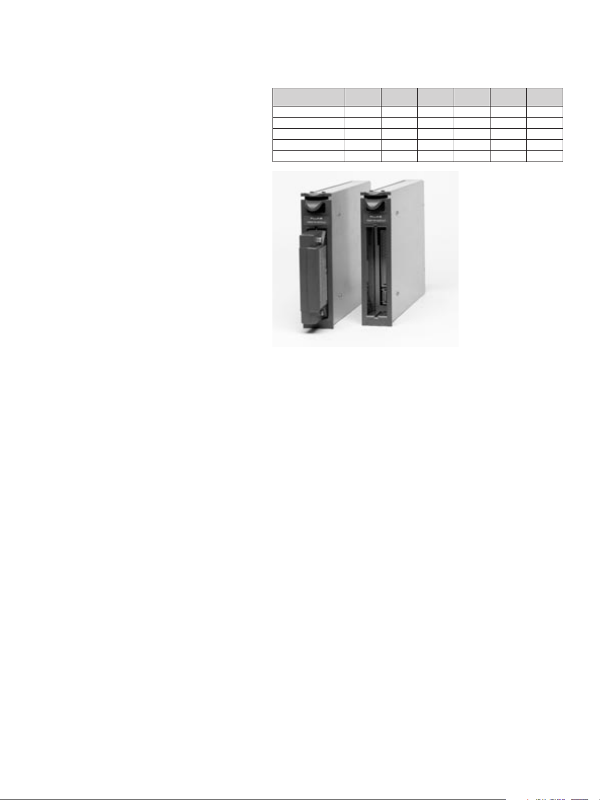
2680A-180: Universal Input
Module requires no external
signal conditioning
Fluke’s patented Universal Input
Module is included with all Fluke
data acquisition products, providing unparalleled thermocouple
accuracy and compatibility with a
broad range of diverse inputs. The
Universal Input Module enables
you to easily measure just about
any electrical or physical parameter without changing hardware or
adding external signal conditioning. You can connect any combination of dc voltage, ac voltage,
thermocouples, current, RTD,
resistance (2- or 4-wire), or frequency measurement inputs
directly to the input module.
Fluke DAQ Software makes
it easy to get the most out of
your data
Each Fluke 2680A and 2686A
comes with our powerful, highlyflexible, yet easy-to-use Fluke DAQ
Configuration Software. Fluke DAQ
allows you to configure the 2680
Series for:
•
Input type
•
Alarms
•
Math functions
•
Totalizer function
•
Digital I/O lines
•
Scan speed
•
Interval
•
Trigger type
You can use Fluke DAQ Software to
set up data files, collect and chart
data in real-time or historical
mode, and manage memory card
files. Using Fluke DAQ, you can
collect data from your system the
way you need to and distribute it
where you want it. And you can
share data with others, anywhere
on your LAN or anywhere around
the world using Web servers.
Fluke DAQ Software also
enables you to integrate Fluke
NetDAQ
®
data acquisition products
(2640A and 2645A) into your
2680 Series system, providing
almost unlimited channels working
together seamlessly.
Optional software extends
system capabilities
Fluke has partnered with industrial
software developer Indusoft to create additional tools to extend the
power of your 2680 Series system.
Optional software tools allow you
to create human machine interfaces and develop custom applications that interact with other
equipment and software packages.
Fluke 2680A-DEVSW:
Development software for
HMI design
The optional 2680A-DEVSW tool is
based on Indusoft Web Studio, an
object oriented development software program that works with
Fluke DAQ Software. This unique
development system allows programmers and non-programmers
to develop modern human
machine interfaces (HMI) which
open graphical windows to your
application.
Fluke DAQ Software: Real time and historical trending
Fluke DAQ Software: Configuration made simple
Universal Input Module
Page 4

4 Fluke Corporation Fluke 2680 Series Data Acquisition Systems
Key features of this powerful
development package include:
•
An extensive graphics library
•
Drag & drop programming
•
More than 140 device drivers
•
OPC client/server compliance
•
Support for DNA, OPC, DDE,
OBDC, XML, SOAP and Active X
Fluke 2680A-OPC: Create
custom applications using
OLE for Process Control
Optional Fluke 2680A-OPC software gives you the freedom to
integrate your 2680 Series into
any OPC-compliant application.
Create custom applications using
2680A-OPC software and just
about any popular industrial software package such as Wonderware,
®
LabVIEW,™Test Point, or
Indusoft Web Studio, as well as
software from Canary Labs, Daisy
Labs, and others. Open, non-proprietary OPC support enables you
to use the software you choose or
the software you create.
Fluke 2680A-DLL library:
For developing or modifying
applications
The 2680A DLL library is designed
for programmers who want to
develop or modify their own
applications for the 2680 Series,
using C++, Visual Basic, and other
languages.
Channel capacity
(2680A or 2686A)
20 to 120 channels per chassis
(6 analog input modules of 20
channels each)
One master alarm (open collector) per chassis
Communications:
10BaseT/100BaseT, TCP/IP via
RJ45 connector, Cat 5
Math functions
In addition to its analog and
digital input channels, each
system supports 60 computed
channels. Calculations include
time & rate, addition, subtraction, multiplication, division,
log, natural log, exponent,
square root, absolute value,
integer function and average.
2680A Series Specifications
Analog to digital converter
2680A-PAI: 18 bit, multi-slope
type
2680A-FAI: 16 bit, multi-slope
type
Common mode rejection
2680A-PAI:
AC: ≥120 dB (50/60 Hz, ±0.1%
max 1 kΩ source imbalance)
DC: ≥120 dB
2680A-FAI:
AC: ≥100 dB (50/60 Hz, ±0.1%
max 1 kΩ source imbalance)
DC: ≥100 dB
Normal mode rejection
50 dB @ 50/60 Hz, ±0.1%
Common mode voltage
maximum
2680A-PAI: 300 VDC or VAC
rms (channels 1.11); 150 VDC
or VAC rms (all other channels)
2680A-FAI: 50 VDC or 30 VAC
rms (all channels)
Measurement speed
(2680A-PAI)
Slow: 6 readings/second
nominal
Medium: 41 (50 Hz), 48 (60
Hz) readings/second nominal
Fast: 143 readings/second
nominal (5 readings/second for
VAC nominal, 140 readings/
second on 300Ω range,
37 readings/second on 3 MΩ
range)
Measurement speed
(2680A-FAI)
Slow: 45 (50 Hz), 54 (60 Hz)
readings/second nominal
Medium: 200 readings/second
nominal
Fast: 1000 readings/second
nominal (5 readings/second for
VAC nominal, 370readings/
second on 300Ω range,
44 readings/second on 3 MΩ
range)
2680A-DEVSW: Powerful HMI development software
•
Automatic language translation
at run-time
•
Internationalization using
Unicode
•
Web display and alarm paging
•
Support for imported graphics
formats
•
The ability to view multiple
clients from one web browser
Page 5

Model 2680A-FAI
DC Voltage Accuracy1, 3
σσ
σσ
σ, ±(%input + V) 18 to 28°C
Range Resolution 90 Day 1 Year
Slow Slow Fast
90 mV 3 µV 0.01%+20 µV 0.013%+23 µV 0.013%+50 µV
300 mV 10 µV 0.01%+40 µV 0.013%+49 µV 0.013%+93 µV
3V 100 µV 0.01%+.3 mV 0.013%+.38 mV 0.013%+.64 mV
30V 1 mV 0.01%+4 mV 0.013%+4.9 mV 0.026%+9.5 mV
150/300V 10 mV 0.01%+30 mV 0.013%+40 mV 0.052%+64 mV
Resistance Accuracy
1,3
(4-wire), 3
σσ
σσ
σ, ± (% input+Ω )
300Ω 10 mΩ 0.02%+60 mΩ 0.02%+.1Ω .02%+.2Ω
3 kΩ 100 mΩ 0.02%+6Ω 0.02%+1Ω .02%+3Ω
30 kΩ 1Ω 0.02%+6Ω 0.02%+10Ω .02%+300Ω
300 kΩ 10Ω 0.5%+80Ω 0.5%+150Ω 1.0%+3 kΩ
3 MΩ 100 Ω 1.3%+1 kΩ 1.3%+2 kΩ 2.0%+200 kΩ
Measurement accuracy
Model 2680A-PAI
Accuracy
1,6
, 3
σσ
σσ
σ, ± °C
Thermocouples
9
18 to 28°C-10 to 60°C
ITS90 90 Day 1 Year 1 Year
Type Temp (°C) Slow Slow Fast Slow Fast
J-100°Cto80°C 0.45 0.5 0.8 0.6 0.8
80°Cto230°C 0.35 0.5 0.7 0.6 0.8
230°Cto760°C 0.4 0.5 0.7 0.8 0.9
K-100°Cto-25°C 0.55 0.6 0.9 0.7 1.0
-25°Cto120°C 0.4 0.5 0.8 0.6 0.9
120°Cto800°C 0.5 0.65 0.9 1.0 1.2
800°Cto1372°C 0.7 1.0 1.3 1. 6 1.9
N-100°Cto-25°C 0.65 0.75 1.2 0.8 1.3
-25°Cto120°C 0.55 0.6 1.0 0.7 1.1
120°Cto1000°C 0.45 0.6 0.9 1.0 1.2
1000°Cto1300°C 0.55 0.75 1.0 1.2 1.5
E-100°Cto-25°C 0.45 0.5 0.8 0.6 0.8
-25°Cto20°C 0.35 0.4 0.6 0.5 0.7
20°Cto600°C 0.3 0.4 0.6 0.5 0.8
600°Cto1000°C 0.4 0.5 0.7 0.9 1.0
T-100°Cto0°C 0.6 0.65 1.0 0.7 1.1
0°Cto150°C 0.4 0.5 0.8 0.6 0.9
150°Cto400°C 0.3 0.4 0.6 0.6 0.8
R 250°Cto600°C 0.9 1.0 2.1 1.2 2.2
600°Cto1500°C 0.8 0.9 1.8 1.3 2.0
1500°Cto1767°C 0.85 0.85 1.9 1.7 2.5
S 250°Cto1000°C 0.95 1.1 2.3 1.3 2.4
1000°Cto1400°C 0.8 1.0 1.9 1.4 2.3
1400°Cto1767°C1.0 1.3 2.2 1.8 2.8
B600°Cto900°C1.2 1.4 3.1 1. 5 3.2
900°Cto1200°C 0.9 1.0 2.2 1.2 2.4
1200°Cto1820°C 0.75 1.0 1.9 1.3 2.2
C0°Cto150°C 0.8 0.9 1.6 1.0 1.7
150°Cto650°C 0.65 0.75 1.4 1.0 1.5
650°Cto1000°C 0.65 0.85 1.4 1.2 1.8
1000°Cto1800°C1.0 1.3 2.1 2.1 2.8
18 00 °Cto2316°C1.6 2.1 3.2 3.4 4.6
L-100°Cto100°C 0.9 1.0 2.0 1.3 2.0
100°Cto800°C 0.5 0.9 1.4 1.2 1.7
800°Cto900°C 0.5 0.7 1.1 1.3 1.5
U-100°Cto0°C1.51.52.6 1.6 3.0
0°Cto600°C 0.6 0.8 1.6 1.1 1.9
Model 2680A-FAI
Accuracy
1,6
, 3
σσ
σσ
σ, ± °C
Thermocouples
9
18 to 28°C-10 to 60°C
ITS90 90 Day 1 Year 1 Year
Type Temp (°C) Slow Slow Fast Slow Fast
J-100°Cto80°C 0.8 0.9 1.6 0.9 1.7
80°Cto230°C 0.7 0.8 1.4 0.9 1.5
230°Cto760°C 0.7 0.8 1.3 1.0 1.5
K-100°Cto-25°C1.01.12.0 1.2 2.1
-25°Cto120°C 0.8 0.9 1.7 1.0 1.8
120 °Cto1000°C 0.9 1.1 1.8 1.5 2.2
1000°Cto1372°C1.2 1.5 2.3 2.0 2.9
N-100°Cto-25°C1.41.52.8 1.5 2.9
-25°Cto120°C1.11.32.3 1.3 2.4
120 °Cto1000°C1.0 1.1 2.0 1.2 2.1
1000°Cto1300°C1.0 1.2 1.9 1.6 2.4
E-100°Cto-25°C 0.8 0.9 1.5 1.0 1.6
-25°Cto20°C 0.7 0.7 1.2 0.8 1.3
20°Cto600°C 0.6 0.7 1.1 0.8 1.2
600°Cto1000°C 0.6 0.8 1.2 1.1 1.5
T-100°Cto0°C1.11.22.2 1.3 2.3
0°Cto150°C 0.9 1.0 1.7 1. 0 1.8
150 °Cto400°C 0.7 0.8 1.4 0.8 1.5
R 250°Cto600°C 2.4 2.7 5.6 2.8 5.7
600°Cto1500°C 2.0 2.3 4.6 2.4 4.8
1500°Cto1767°C 2.0 2.3 4.5 2.8 5.1
S 250°Cto1000°C 2.6 2.8 5.9 2.9 6.0
1000°Cto1400°C 2.0 2.3 4.6 2.6 5.0
1400°Cto1767°C 2.3 2.7 5.3 3.3 5.9
B600°Cto1200°C 3.6 3.9 8.5 4.0 8.6
1200°Cto1550°C2.1 2.4 5.0 2.6 5.2
1550°Cto1820°C 2.0 2.3 4.7 2.7 5.0
C0°Cto150°C1.92.0 4.0 2.1 4.2
150 °Cto650°C1.6 1.7 3.5 1.8 3.6
650°Cto1000°C1.4 1.7 3.2 2.0 3.5
1000°Cto1800°C 2.0 2.5 4.5 3.2 5.3
18 00 °Cto2316°C3.1 3.8 6.8 5.1 8.1
L-100°Cto100°C1.21.32.9 1.6 3.1
100 °Cto800°C 0.9 1.0 2.1 1.2 2.3
800°Cto900°C 0.7 0.8 1.3 1.0 1.5
U-100°Cto0°C 2.0 2.1 4.3 2.2 4.6
0°Cto600°C1.3 1.4 2.5 1.6 2.6
Model 2680A-PAI
DC Voltage Accuracy1, 3
σσ
σσ
σ, ±(%input + V) 18 to 28°C
Range Resolution 90 Day 1 Year
Slow Slow Fast
90 mV .3 µV 0.01%+7 µV 0.013%+8 µV 0.013%+18 µV
300 mV 1 µV 0.01%+15 µV 0.013%+17 µV 0.013%+35 µV
3V 10 µV 0.01%+.1 mV 0.013%+.15 mV 0.013%+.2 mV
30V 100 µV 0.01%+1.5 mV 0.013%+1.7 mV 0.026%+3.5 mV
150/300V 1 mV 0.01%+15 mV 0.013%+17 mV 0.052%+35 mV
Resistance Accuracy
1,3
(4-wire), 3
σσ
σσ
σ, ± (% input+Ω )
300Ω 1 mΩ 0.015%+20 mΩ 0.02%+30 mΩ 0.02%+120 mΩ
3 kΩ 10 mΩ 0.02%+.3Ω 0.02%+.5Ω 0.02%+.1.2Ω
30 kΩ 100 mΩ 0.03%+3Ω 0.03%+5Ω 0.04%+15Ω
300 kΩ 1Ω 0.1%+40Ω 0.1%+60Ω 0.2%+150Ω
3 MΩ 10 Ω 0.25%+800Ω 0.25%+1 kΩ 0.5%+1.5 k
Fluke 2680 Series Data Acquisition Systems Fluke Corporation 5
Page 6

6 Fluke Corporation Fluke 2680 Series Data Acquisition Systems
1
Total instrument accuracy for the indicated time period and ambient temperature
range. Includes A/D errors, linearization conformity, initial calibration error,
isothermality errors, reference junction conformity and power line voltage effects
within the range from 100VAC to 264VAC.
2
Sine wave inputs >2000 counts (slow), >200 counts (fast). Accuracies for crest
factor ≤2.0.
3
For two-wire measurements add 5Ω to basic accuracy (does not include leadwire resistances).
4
For two-wire measurements add 700-1000Ω to basic accuracy (does not include
lead-wire resistances). Ohms varies due to the resistance of the solid state
switches.
5
DIN/IEC 751 only, assumes no lead-wire resistance errors.
6
Resolution is 0.02°C or 0.04°F over the useful range of base metal thermocouples
(J, K, T, E, N, L, U) and 0.1°C or 0.2°F resolution for types R, S, B, and C with
slow scan.
7
Resolution is 0.2°C or 0.4°F over the useful range of base metal thermocouples (J,
K, T, E, N, L, U) and 1.0°C or 2.0°F resolution for types R, S, B, and C with slow
scan.
8
Accuracy for both slow and fast scan speeds.
9
Open thermocouple detection is performed on each thermocouple channel unless
defeated by computer command.
10
Using Stein hart – Hart thermistor polynomial: T = A+B (InR) + C (InR)
3
T = temp in °K
A, B and C = fitting constants
R = resistance of thermistor in Ω.
Measurement accuracy cont.
Model 2680A-PAI
AC Voltage
Range Resolution Frequency Accuracy
1,2
,3
σσ
σσ
σ,± (% input+counts)
Slow Fast
300 mV 1 µV 20 Hz-50 Hz 3.0%+25 6.0%+50
50 Hz-20 kHz 0.4%+25 1.0%+50
20 kHz-50 kHz 2.0%+30 3.0%+50
50 kHz-100 kHz 5.0%+50 5.0%+100
3V 100 µV Same frequencies, similar accuracies as above
30V 1 mV Same frequencies, similar accuracies as above
150/300V 10 mV Same frequencies, similar accuracies as above
RTD (Pt 100) Accuracy
1,5
, 3
σσ
σσ
σ, ± °C (4-wire)
Temperature Resolution 90 Day, 1 Year,
°C °C18 to 28°C18 to 28°C
Slow Slow Slow
-200 0.003 0.06 0.09
0 0.003 0.09 0.13
10 0 0.003 0.10 0.16
300 0.003 0.14 0.21
600 0.003 0.19 0.30
Thermistor10 2 k to 100 kΩ
-40 °C to 150 °C 0.003 0.3 0.4
Frequency Measurement Accuracy
1,8
, -20 to 60°C
Range Resolution Accuracy, 3
σσ
σσ
σ,± (% input +Hz)
Slow Fast Slow Fast
15 Hz-900 Hz 0.01 Hz 0.1 Hz 0.05%+0.02 Hz 0.05%+0.2 Hz
900 Hz-9 kHz 0.1 Hz 1 Hz 0.05%+0.1 Hz 0.05%+1 Hz
9 kHz-90 kHz 1 Hz 10 Hz 0.05%+1 Hz 0.05%+10 Hz
90 kHz-900 kHz 10 Hz 100 Hz 0.05%+10 Hz 0.05%+100 Hz
1 MHz 100 Hz 1 kHz 0.05%+100 Hz 0.05%+1 kHz
Frequency Measurement Sensitivity (sine wave)
Frequency Minimum Signal Maximum Signal
15 Hz - 200 Hz 100 mV rms 150/300V rms
200 Hz - 70 kHz 100 mV rms 30V rms
70 kHz - 100 kHz 100 mV rms 20V rms
100 kHz - 200 kHz 150 mV rms 10V rms
200 kHz - 300 kHz 150 mV rms 7V rms
300 kHz - 1 MHz linearly increasing from linearly decreasing from
150 mV rms at 300 kHz to 7V rms at 300 kHz to
2V rms at 1 MHz 2V rms at 1 MHz
Model 2680A-FAI
AC Voltage
Range Resolution Frequency Accuracy
1,2
,3
σσ
σσ
σ,± (% input+counts)
Slow Fast
300mV 10 µV 20 Hz-50 Hz 3.0%+25 6.0%+50
50 Hz-20 kHz 0.4%+25 1.0%+50
20 kHz-50 kHz 2.0%+30 3.0%+50
50 kHz-100 kHz 5.0%+50 5.0%+100
3V 100 µV Same frequencies, similar accuracies as above
30V 1 mV Same frequencies, similar accuracies as above
RTD (Pt 100) Accuracy
1,5
, 3
σσ
σσ
σ, ± °C (4-wire)
Temperature Resolution 90 Day, 1 Year,
°C °C18 to 28°C18 to 28°C
Slow Slow Slow
-200 0.03 0.16 0.25
0 0.03 0.20 0.31
10 0 0.03 0.23 0.34
300 0.03 0.30 0.41
600 0.03 0.53 0.63
Thermistor 10 k to 100 kΩ
-40 °C to 150 °C 0.03 0.4 0.5
Frequency Measurement Accuracy
1,8
, -20 to 60°C
Range Resolution Accuracy, 3
σσ
σσ
σ,± (% input +Hz)
Slow Fast Slow Fast
15 Hz-900 Hz 0.01 Hz 0.1 Hz 0.05%+0.02 Hz 0.05%+0.2 Hz
900 Hz-9 kHz 0.1 Hz 1 Hz 0.05%+0.1 Hz 0.05%+1 Hz
9 kHz-90 kHz 1 Hz 10 Hz 0.05%+1 Hz 0.05%+10 Hz
90 kHz-900 kHz 10 Hz 100 Hz 0.05%+10 Hz 0.05%+100 Hz
1 MHz 100 Hz 1 kHz 0.05%+100 Hz 0.05%+1 kHz
Frequency Measurement Sensitivity (sine wave)
Frequency Minimum Signal Maximum Signal
15 Hz - 200 Hz 100 mV rms 30V rms
200 Hz - 70 kHz 100 mV rms 30V rms
70 kHz - 100 kHz 100 mV rms 20V rms
100 kHz - 200 kHz 150 mV rms 10V rms
200 kHz - 300 kHz 150 mV rms 7V rms
300 kHz - 1 MHz linearly increasing from linearly decreasing from
150 mV rms at 300 kHz to 7V rms at 300 kHz to
2V rms at 1 MHz 2V rms at 1 M
Page 7
Fluke 2680 Series Data Acquisition Systems Fluke Corporation 7
2680A-DIO
Totalizing input
Pre-settable starting count
up/down counter
DC coupled, non-isolated, max
+30V, min -4V
Max count: 4,294,967,295
Minimum signal: 2V peak
Threshold: 1.4V
Rate: 0-5 kHz (debounce off)
Hysteresis: 500 mV
Input debouncing: None or
1.66 ms
Digital inputs/outputs: 20
Threshold: 1.4V
Hysteresis: 500 mV
Maximum input: +30V,
min -4V; non-isolated
Logical “zero” output:
0.8V max |out = -1.0 mA
(1 LSTTL load equivalent)
1.8V max |out = -20 mA
3.25V max |out = -50 mA
Logical “one” output:
Output voltage depends on
external load
3.8V min|out = 0.05 mA
(1 LSTTL load equivalent)
Relays
Quantity: 8
Type: Form C; DPST
Current: 1 amp, non-inductive
Operation time: 75 ms
Alarm associations
Each Digital I/O may be randomly assigned as a digital
input, status output, or alarm
output (associated with any
input channel or channels)
Trigger input
Minimum pulse: 5 µs
Minimum latency: 100 ms
Input “High”: 2.0V min,
7.0V max
Input “Low”: -0.6V min, 0.8V
max non-isolated, contact
closure and TTL compatible
Clock
Accurate to within 1 minute/
month for 0°C to 50°C range
General Specifications
Power
100 to 240 VAC, 50 or 60 Hz
100 VA max, or 9 to 45 VDC
(50W DC) (if both sources are
applied simultaneously, the
greater of AC or DC is used.),
at 120 VAC the equivalent DC
voltage ~14.5V
Temperature, humidity
(non-condensing)
Operating: -20°C to 28°C,
≤90% RH; 28°C to 40°C, ≤75%
RH; 40°C to 60°C, ≤50% RH
Storage: -40°C to 70°C, 5% to
95% RH
Altitude
Operating: 2000m
Storage: 12,200m
Standards
All inputs: IEC Overvoltage
rating Category II
Product conforms to the following safety and emisssion
standards:
EN50082-2
EN55022-1
EN55011 class A
EN610000-4-2,3,4,6,8
EN61326
EN61010 -1, CAT II
CSA C22.2 No. 1010.1
Operating temperature
-20°C to 60°C (-4°F to +140°F)
Storage temperature
-40°C to 70°C (-40°F to +158°F)
Size
18.6˝ x 17˝ x 9.3˝
(473 mm x 423 mm x 237 mm)
Weight
2680A/2686A chassis only:
18.86 lbs. (8.47 kg)
2680A-FAI: 1.74 lbs. (0.79 kg)
2680A-PAI: 2.66 lbs. (1.21 kg)
2680A-DIO: 1.75 lbs. (0.80 kg)
Interfaces
Ethernet: Conforms to IEEE
802.3 Ethernet standard,
compatible with 100BaseT and
10BaseT standards, uses
TCP/IP protocol
RS-232C: For calibration only
System Requirements
System Requirements:
IBM compatible, Pentium II
processor, 333 MHz
Microsoft Windows
NT/98/2000/XP
64 MB RAM
150 MB free hard disk space
VGA or SVGA display, 100%
IBM compatible with 2 MB
Video RAM (VRAM)
CD-ROM Drive
Microsoft Internet Explorer 4.0
or later
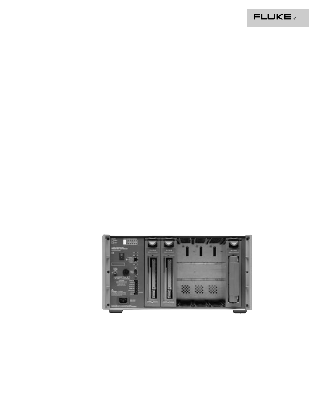
Easy access to expansion slots and rear panel
Page 8

Fluke Corporation
PO Box 9090, Everett, WA USA 98206
Fluke Europe B.V.
PO Box 1186, 5602 BD
Eindhoven, The Netherlands
For more information call:
In the U.S.A. (800) 443-5853 or
Fax (425) 446-5116
In Europe/M-East/Africa (31 40) 2 675 200 or
Fax (31 40) 2 675 222
In Canada (800)-36-FLUKE or
Fax (905) 890-6866
From other countries +1 (425) 446-5500 or
Fax +1 (425) 446-5116
Web access: http://www.fluke.com/
©2002 Fluke Corporation. All rights reserved.
Trademarks are the property of their respective owners.
Specifications subject to change without notice.
Printed in U.S.A. 3/2002 1638781 D-ENG-N Rev B
Fluke. Keeping your world
up and running.
Models
Model # Description
2680A Data Acquisition System Chassis
6 slots
2686A Data Logging System Chassis
6 slots
ATA Flash memory drive
Includes 16 MB memory card
2680A-FAI* Fast Analog Input Module
20 universal channels
50 V max isolation
16-bit resolution
1000 ch/sec scan rate
2680A-PAI* Precision Analog Input Module
20 universal channels
300 V Max isolation
18-bit resolution
140 ch/sec scan rate
2680A-DIO* Digital I/O and relay module (one per chassis),
20 digital input/outputs, 8 1-Amp contacts, 1 totalizer
*Includes universal input module or DIO connector module as appropriate
Software
Model # Description
Fluke DAQ Configuration software for Fluke 2680 Series and NetDAQ
Series.
(Included with purchase of 2680A, 2686A system chassis)
2680A-DEVSW Indusoft Web Studio development software for Fluke DAQ
2680A-DLL DLL Library for Fluke 2680 Series
2680A-OPC OPC software for Fluke 2680 Series
Accessories
Model # Description
2680A-180 Universal Input Module, extra connector
2680A-102 2680A-DIO connector module, extra connector
2620A-101 Shunt resistor set (12 ea), 10 ohm, .1%
2686A-800 16 MB ATA Flash memory card for Fluke 2686A
2686A-801 128 MB ATA Flash memory card for 2686A
2686A-802 256 MB ATA Flash memory card for 2686A
2686A-805 512 MB ATA Flash memory card for 2686A
2686A-810 1 GB ATA Flash memory card for 2686A
Y2680 19-inch rack mount kit for Fluke 2680 Series
Sample Order:
The following is a sample order for a data logger with 40 channels of analog
input and a digital output module.
Model # Description Quantity
2686A Fluke 2686A Data Logging System Chassis 1
with 16 MB memory card
2680A-PAI Precision Analog Input Module for Fluke 2680 1
Series, 20 channels
2680A-FAI Fast Analog Input Module for Fluke 2680 Series, 1
20 channels
2680A-DIO Digital output and relay alarm card for Fluke 1
2680 Series
Ordering Information
Calibration
Each analog input module comes
with a serialized Statement of
Calibration Practices and calibration
seal. Placement of modules between
chassis slots or between chassis
does not affect module calibration.
The chassis and 2680A-DIO do not
require calibration.
Sealed calibration is performed
via RS-232 port on the chassis.
Recommended 1-year calibration
cycle.
 Loading...