

Page 1
Electric and Magnetic Field Measurement
5 Hz to 32 kHz
EFA-300 Field Analyzer
For Isotropic Measurement of Magnetic and Electric Fields
Evaluation of Field Exposure Compared to ♦
Major Standards and Guidances (selectable)
Shaped Time Domain (STD) – an innovative ♦
technique for signal-shape-independent
field measurements
Fast Fourier Transform (FFT) Spectral Analysis ♦
Peak Value Measurement with Proper Phase ♦
Large-Capacity Data Storage ♦
Remote Control ♦
Applications
The EFA-300 is an ideal field analyzer for measuring magnetic and electric fields in
the workplace and in public spaces. It is designed for professional users in the power
industry, at municipal utilities, by insurers, and for health and safety professionals in
industry. In the low frequency range, it handles virtually any required measurement,
simply and precisely. This instrument provides field analysis using an FFT computation in addition to measuring magnetic and electric fields. The innovative STD mode
opens up further application areas. With this new mode the measurement results for
magnetic and electric field strength are displayed as a Percent of Standard, regardless
of the signal shape. This mode enables fast and reliable measurement and evaluation of the typical fields where complex, non-sinusoidal signals are common, e.g., in
industrial applications that use resistance welding. Resistance welding issues surface
in the traditional 50/60 Hz systems as well as in the newer medium-frequency switching units.
Basic Operation
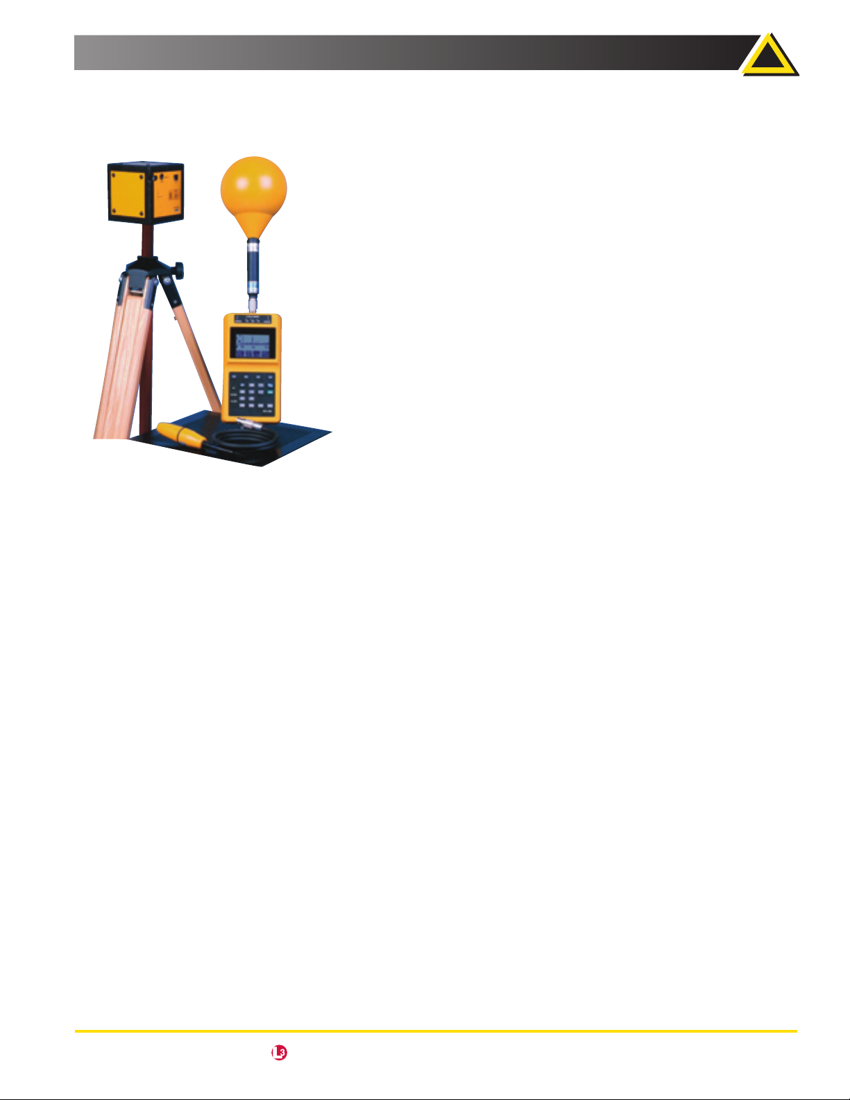
The EFA-300 has a built-in, isotropic, magnetic field probe. Optional external probes
can be used to handle other applications. For example, an isotropic B-field probe with
high sensitivity and a large (100 cm2) cross-sectional area is available for the standardized measurement of dissimilar magnetic fields.
For measurements in hard-to-reach places, a miniature 3 cm diameter B-field “sniffer”
probe is available.
The EFA-300 includes a cubic-shaped, isotropic, E-field module. This E-field module
contains both the sensor and circuitry that allows it to be operated independent of
the base unit. The base instrument, or a computer with the EFA-TS remote software,
can be used to read results in real-time and control the functions of the module. In the
data-logging mode, the E-field module can be operated independently. Stored data
can be read and analyzed at a later date using a computer and the EFA-TS software.
The major advantage of operating the E-field module remotely is that it greatly reduces the influence of the human body on the electric field you are trying to measure.
narda Safety Test Solutions an communications company USA • Germany • Italy
USA TEL: (1) 631 231-1700 • FAX: (1) 631 231-1711 • E-MAIL: NardaSTS@L-3COM.com • www.narda-sts.us
29
Page 2
Electric and Magnetic Field Measurement
EFA-300 Field Analyzer
Operating Modes
Various standards and guidances take into account the fact
that signal shape plays a major role in determining the workplace limit. For example, in Germany the employer’s liability
insurance association guideline on “Electromagnetic Fields”
specifies different evaluation guidelines for different field
shapes. Stationary sinusoidal and pulsed fields are differentiated. Occasionally both the RMS value and the peak value,
(with proper phase) are critical for assessing exposure in the
low-frequency range.
This new generation of equipment greatly simplifies the
measurement process. Besides measuring the RMS and peak
values with the classic filter technique, the EFA-300 includes
the highly innovative mode known as STD (Shaped Time
Domain). With this new mode, both instruments achieve a
new standard in simple but reliable measurement, even in
very complex environments. A standard’s variation with
frequency can be automatically taken into account and
normalized. Field strength results are provided in a “Percent
of Standard.” Knowledge about the signal shape, frequency,
or frequency-dependent limits is no longer needed.
For individual frequency and field strength analysis, a very
fast FFT (Fast Fourier Transform) mode, which includes evaluation of harmonics, is available as an option.
Field Strength Mode
Selective and Broadband Field Strength Measurements
In many practical applications, such as proximity to highvoltage lines and transformer stations, this measurement is
simple and produces accurate results. If the field under test
has essentially a single frequency component, the broadband mode is the best choice. A broadband measurement of
the magnetic field in the frequency range from 5 Hz to 32 kHz
is made using the built-in isotropic probe. The Model EFA-300
can also be used to measure the electric field with the external, cube-shaped E-field module.
For more precise analysis or multi-frequency fields, band pass
and band reject filters are available in the frequency range of
15 Hz to 2 kHz with user-editable filter lists. Operation is configured to allow fast switching between common settings,
e.g., broadband and bandpass filter.
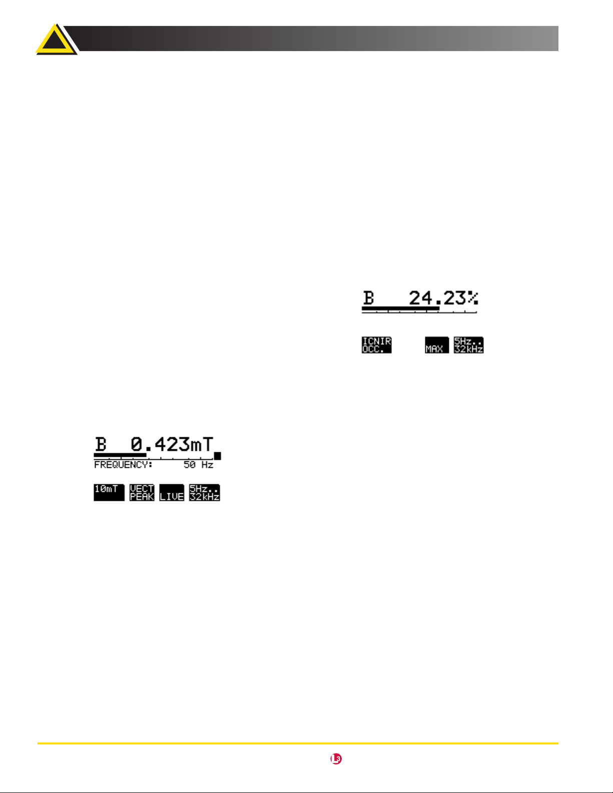
In broadband mode, the large, backlit display provides measurement and frequency results simultaneously.
Two plug-in, B-field, probes extend the range of possibilities.
The small “sniffer” probe has a 3 cm diameter while the larger,
more sensitive probe, has a 100 cm
Users can choose between RMS and peak value measurement
from less than 1 nT to 31.6 mT. The EFA-300 can also measure
the E-field from less than 1 V/m to 100 kV/m.
2
cross-sectional area.
STD (Shaped Time Domain) Evaluation Mode
Innovative Technique for
Signal-Shape-Independent Field Measurements
In many situations, detailed knowledge of the field, test
equipment and other auxiliary conditions are necessary to
obtain insight into the degree of exposure when using traditional measurement equipment. Standardized evaluation
entails complicated analysis. However, the new and innovative “Shaped Time Domain” technique simplifies the process.
The frequency dependency of standards is automatically
incorporated when using shaped-frequency-response measurements. Suitable detectors are provided for measuring
the RMS and peak values. The analysis takes into account the
phase of the individual components.
The B- or E-field is measured over the entire frequency
range up to 32 kHz in real time and displayed as a Percent of
Standard.
STD analysis is not limited to specific signal shapes. Signals
with one or more frequencies and pulsed signals are no
problem. Pulsed signal measurements are possible since the
time-domain limits (e.g., those specified for selected pulsed
signals) can be directly converted into frequency-domain limits. Proper evaluation in a personal safety context is achieved
quickly and reliably using the STD technique.
To evaluate the field, six limit curves (standards) are stored
in the device. A simple download procedure can be used to
update the instrument to cover new standards.
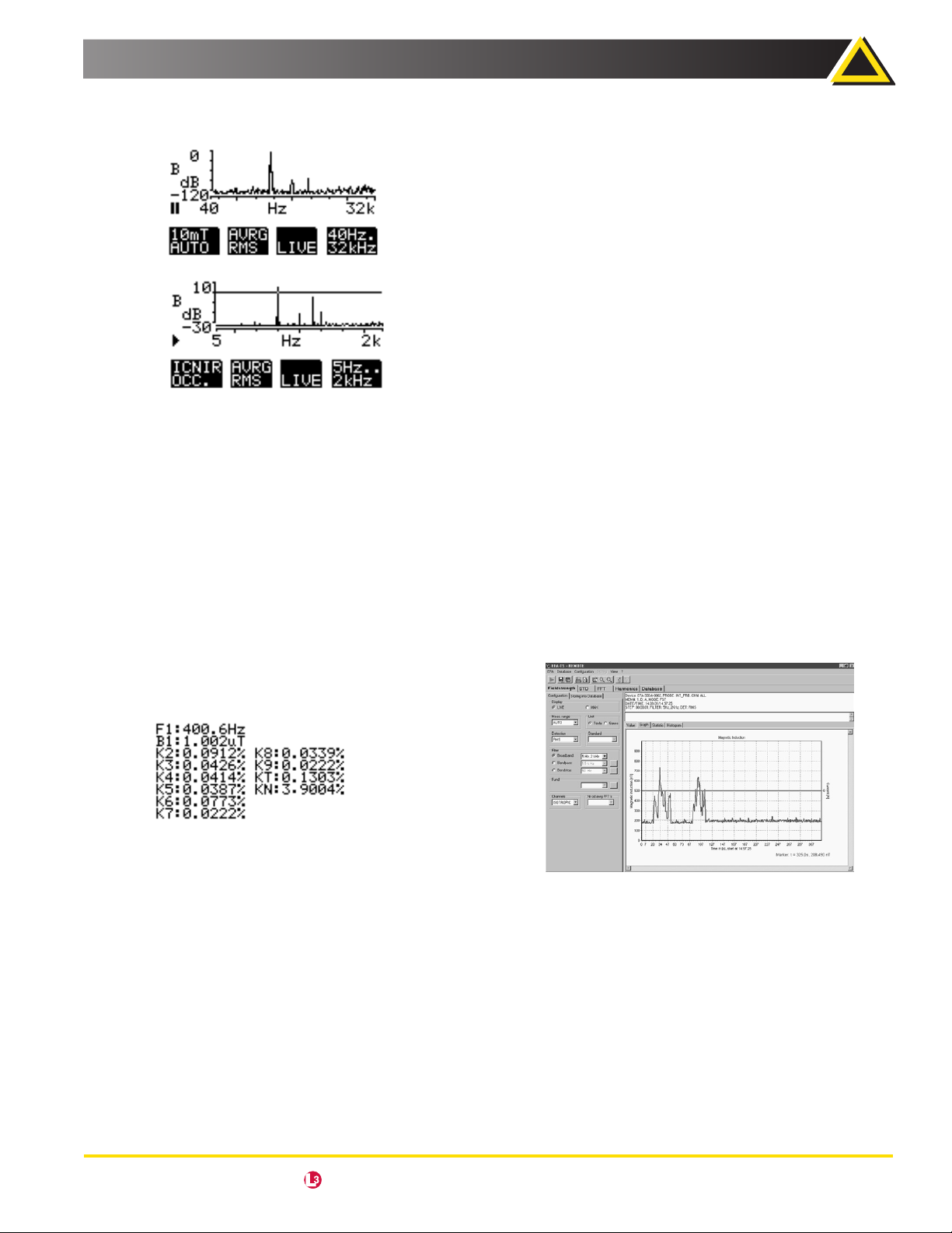
Spectrum FFT Mode (Optional)
Spectrum analysis considerably simplifies the process of
quickly evaluating multi-frequency signals up to 32 kHz. All
spectral components are evaluated at once.
To provide a spectrum, the signal curve versus time is recorded via the probe and converted into the frequency domain
using a mathematical procedure known as “Fast Fourier
Transform.”
30
narda Safety Test Solutions an communications company USA • Germany • Italy
USA TEL: (1) 631 231-1700 • FAX: (1) 631 231-1711 • E-MAIL: NardaSTS@L-3COM.com • www.narda-sts.us
Page 3
Electric and Magnetic Field Measurement
The EFA-300 is so powerful that even transient events ranging
up to 2 kHz can be analyzed in real time.
Evaluation is supported by graphics to clearly show the frequency spectrum and by cursor functions with frequency
and level indications. The RMS and peak values of the nine
most significant frequency components are easy to read.
You can also use this mode to normalize the display to a given
standard. The measured value is then displayed relative to its
associated standard. In visual terms, the frequency-dependent standard becomes a straight line. This makes it easy to
determine the relevancy of each spectral component.
EFA-300 Field Analyzer
Analyze the data and provide a graphic representation of •
the results to support the user in the preparation of measurement reports
FEATURES
Windows® interface to configure the instrument and/or to •
control it remotely.
Graphic representation of data stored in the internal mem-•
ory of the instrument or in a file:
Line diagrams show field strength or Percent of −
Standard versus time. Can be used in real time.
Display of spectrum −
−
Bar graph of harmonics
2D-views with import possibility: background maps −
for Matrix-data sets
Graphic tools – zoom, marker, set-up for scale, color/ −
thickness of lines, etc.
Additional Analysis Functions: •
Statistics – mean and maximum values, histogram, −
and number of values over a defined threshold
Peak list for spectrums −
Export Functions•
Data sets as ASCII-files −
Graphic screen into the clipboard −
Harmonic Analysis Mode
(Included with Spectrum FFT Mode)
This mode enables fast, convenient evaluation of the harmonic spectrum. A table lists the field strengths of the measured
fundamental frequency along with up to 8 harmonics.
This feature is very useful for a “hands-off” verification of power quality (“Quality of Service”) in addition to occupational
safety applications.
Remote And Data Analysis
Software EFA-TS
This optional software is used to:
Provide remote control of the field analyzer •
and data readout
Download the data stored in the device•
Save acquired data on the computer •
MINIMUM SYSTEM REQUIREMENTS
Microsoft® Windows® 95 or Higher −
Windows NT® 4.0 or Higher −
Pentium Processor −
Min. 4 MB RAM −
Graphic card VGA 640/480, 256 colors −
CD-ROM
−
narda Safety Test Solutions an communications company USA • Germany • Italy
USA TEL: (1) 631 231-1700 • FAX: (1) 631 231-1711 • E-MAIL: NardaSTS@L-3COM.com • www.narda-sts.us
31
Page 4

Electric and Magnetic Field Measurement
8000 mT • Hz
Frequency
( ) • √ 2
40000 mT • Hz
Frequency
( ) • √ 2
EFA-300 Field Analyzer
Specifications
MAGNETIC B FIELD
ELECTRIC E FIELD
100 cm Probe Internal Probe 3 cm Probe
Sensor System Coil (internal or external) Plate Electrode
Measurement Axis, selectable Tri-Axial (Isotropic) or Single Axis
FIELD STRENGTH MODE
Broadband (+0/-3 dB),
Frequency
Range
selectable
Band Pass / Band Reject
Filter, adjustable
Detection, selectable
Measurement
Range
Nominal 100 nT to 32 mT 100 nT to 32 mT 100 nT to 32 mT 10 V/m to 100 kV/m
Damage Level (Peak) 91 mT
Damage Level
(Peak)
Damage Level (Peak)
For magnetic field
a
@ ≤125 Hz 91 mTa @ ≤625 Hz 91 mTa @ ≤625 Hz 280 kV/m
a
5 Hz to 2 kHz, 30 Hz to 2 kHz, 5 Hz to 32 kHz or 30 Hz to 32 kHz
15 Hz to 2 kHz (resolution 0.1 Hz)
RMS (averaging time 1 sec.)
Peak Value (proper phase)
probes depending on
frequency
32
Broadband,
30 Hz to 2 kHz
Noise Level
(RSM), typical
Broadband,
5 Hz to 32 kHz
Band Pass Filter,
50 Hz to 400 Hz
Broadband,
Uncertainty,
b
typical
5 Hz to 2 kHz
Broadband,
5 Hz to 32 kHz
Band Pass Filter, 50 Hz
to 400 Hz
a
The upper limit decreases linearly with increasing frequency above the mentioned frequency.
Overload limit for 100 cm² Probe =
Overload limit for 3 cm and internal Probe 100 cm² Probe =
b
Uncertainty includes all partial uncertainties (absolute, linearity, frequency response, and isotropy) as well as temperature and humidity related deviations.
Signal sinusoidal, level >10% of selected measurement range; additional uncertainties apply with the steep frequency band limits.
4 nT 100 nT 20 nT 0.7 V/m
10 nT 200 nT 50 nT 4.5 V/m
0.8 nT 25 nT 5 nT 0.14 V/m
±3% @ ≥40 nT ±5% @ ≥1µT ±4% @ ≥200 nT ±3% @ ≥5 V/m
±3% @ ≥80 nT ±8% @ ≥2 µT ±5% @ ≥400 nT ±3% @ ≥40 V/m
±3% @ ≥10 nT ±5% @ ≥250 nT ±4% @ ≥50 nT ±3% @ ≥1 V/m
narda Safety Test Solutions an communications company USA • Germany • Italy
USA TEL: (1) 631 231-1700 • FAX: (1) 631 231-1711 • E-MAIL: NardaSTS@L-3COM.com • www.narda-sts.us
Page 5

Electric and Magnetic Field Measurement
EFA-300 Field Analyzer
MAGNETIC B FIELD
ELECTRIC E FIELD
100 cm Probe Internal Probe 3 cm Probe
EXPOSURE STD MODE
Frequency Range (+0/-3 dB) 5 Hz to 32 kHz
Exposure Evaluation Compared to Standards Stored in Meter
c
Measurement Range / Overload Limit 200% 200% 200% 200%
d
Noise Level, typical
(for ICNIRP Occupational)
Uncertainty, typical (percent of reading)
b
<0.4% <2% <1% <5%
±4% ±9% ±6% ±4%
SPECTRUM FFT / HARMONICS MODE (Optional)
Frequency Range
Fundamental Range
(HARMONICS only)
Resolution
by Marker:
Frequency
Scale,
selectable:
2 kHz Range 0.01 Hz
32 kHz Range 0.1 Hz
2 kHz Range Full-Scale Logarithmic or 100 Hz Wide Linear Span
32 kHz Range Full-Scale Logarithmic or 1000 Hz Wide Linear Span
Detection, selectable
10 Hz to 10 kHz (Option, FFT 5 Hz-32 kHz)
RMS, RMS Average, Peak Value or Vector Peak Value
(at each single frequency, proper phase)
5 Hz to 2 kHz
40 Hz to 32 kHz
10 Hz to 400 Hz
Measurement Range See FIELD STRENGTH MODE
Noise/ Spurious Level (RSM), typical See Table 1 (on next page)
Uncertainty, by marker
b
See FIELD STRENGTH MODE
Results Scale, selectable 20 dB to 120 dB (logarithmic)
Data Acquisition,
(start/stop)
2 kHz Range Continuous and Overlapping / Seamless
32 kHz Range Continuous
Window Length: 2 kHz Range 1.0 second
32 kHz Range 0.1 second
Result
Averaging,
selectable
Graphical Display, selectable
(SPECTRUM FFT only)
Result List, tabular
(HARMONICS only)
2 kHz Range 1, 2, 4, or 8 seconds
32 kHz Range 4, 8, 16, or 32 Spectra
Result: Absolute or Normalized to Reference Limit of Selected Standard;
Marker Displays 9 Highest Peaks within Selected Frequency Range
nd
Result of 2
to 9th Harmonice and Total Distortion (with/within noise),
Referenced to the Level of Fundamental Frequency
MEASUREMENT DATA MEMORY (individual in B- and E- Field unit)
Capacity, typical (dependent on setting) 3600 Single Values or 22 Spectral Analyses
Control: Field Strength &
Exposure STD Modes
Spectrum FFT &
Harmonics Modes
Manual or Sequence Timer or Sequence Spatial-Assigned
Manual Only
b
Uncertainty includes all partial uncertainties (absolute, linearity, frequency response, and isotropy) as well as temperature and humidity related deviations.
Signal sinusoidal, level >10% of selected measurement range; additional uncertainties apply with the steep frequency band limits.
c
Stored standards can be updated by software: e.g. ICNIRP: occupational, general public; BGV B11: Exp. (2 h/d), Exp. 1, Exp. 2; VDE 0848: draft
d
Dependent on selected standard.
e
Limited by selected frequency range
narda Safety Test Solutions an communications company USA • Germany • Italy
USA TEL: (1) 631 231-1700 • FAX: (1) 631 231-1711 • E-MAIL: NardaSTS@L-3COM.com • www.narda-sts.us
33
Page 6

Electric and Magnetic Field Measurement
EFA-300 Field Analyzer
General Specifications
B-FIELD UNIT E-FIELD MODULE
Display LCD Dot Matrix 128x64 Pixel with Backlight Via B-Field Unit
Alarm, Adjustable Threshold Acoustical, Optical Via B-Field Unit
Current Documentation
(Specific Modes Only)
Interface (Remote Control, Data Memory) Optical, Serial (RS-232)
Operating Temperature Range 0°C to +50°C
Humidity <95% or <29 g/m³ Occasional Brief Condensation Tolerable
Continuous
Operating
Interval, typical
Calibration Interval, recommended 24 Months
Battery NiMH Batteries (5x C-cell), exchangeable NiMH Batteries, built in
Measurement
Programmed
Sequence Time
Input of Prevailing and Reference Current Value;
Storage with Measurement Value of Field
10 Hours
24 Hours
N/A
Dimensions, approximate
Weight, approximate 2.2 lbs. (1000 g) 2.2 lbs. (1000 g)
4.3 x 7.9 x 2.4 inches
(110 x 200 x 60 mm)
4.1 x 4.1 x 4.1 inches
(105 x 105 x 105 mm)
Table 1: Spectrum FFT Sensitivity (Noise / Spurious)
2 kHz Range
32 kHz Range
MAGNETIC B FIELD
100 cm2 Probe Internal Probe 3 cm Probe
<45 nT @
<4 nT @ >48 Hz
<0.05 nT @ noise floor
<2 nT @ <200 Hz
<0.3 nT @ 200 Hz to 20 kHz
<0.6 nT @ >20 kHz
<0.07 nT @ noise floor
≤48 Hz
<400 nT @≤48 Hz
<42 nT @ >48 Hz
<2 nT @ noise floor
<22 nT @ <200 Hz
<11 nT @ 200 Hz to 20 kHz
<11 nT @ >20 kHz
<1.5 nT @ noise floor
<260 nT @≤48 Hz
<23 nT @ >48 Hz
<0.2 nT @ noise floor
<10 nT @ <200 Hz
<2 nT @ 200 Hz to 20 kHz
<3 nT @ >20 kHz
<0.3 nT @ noise floor
ELECTRIC E FIELD
<0.3 V/m @≤48 Hz
<0.1 V/m @ >48 Hz
<0.02 V/m @ noise floor
<0.1 V/m @
<3 V/m @ >20 kHz
<0.05V/m @ noise floor
≤20 kHz
34
narda Safety Test Solutions an communications company USA • Germany • Italy
USA TEL: (1) 631 231-1700 • FAX: (1) 631 231-1711 • E-MAIL: NardaSTS@L-3COM.com • www.narda-sts.us
Page 7

Electric and Magnetic Field Measurement
EFA-300 Field Analyzer
Ordering Information
EFA300 ELECTRIC AND MAGNETIC FIELD ANALYZER Part Number
Basic Unit (EFA-300, EM Field Analyzer System, 5 Hz-32 kHz), Calibrated
Mode: FIELD STRENGTH, EXPOSURE STD, HARMONIC ANALYSIS
Hard case for EFA-300, O/E Converter ORSD-9 Universal Cable, Fiber Optic Duplex (1000 µm), 2m
Software, EFA-300 Tools, Power Supply 9 VDC, 100 V-240 VAC, all Plugs
Operating Manual EFA--300
PROBE, ELECTRIC FIELD, FOR EFA300
E-Field-Probe 5 Hz-32 kHz for EFA-300, Calibrated
Power Supply 9VDC, 100 V-240 VAC, all Plugs, Cable, Fiber Optic Duplex (1000 µm), 10m
Tripod, Non-Conductive, 1.65 m with Carrying Bag
SET
EFA-300, EM Field Analyzer Set (2245/301 with Electrical Field Probe 2245/302) 2245/30
EFA-300, EM Field Analyzer Set (with Electrical Field Probe) and Option FFT 32 kHz 2245/30/FFT-32
EFA-300 with Option FFT 32 kHz 2245/301/FFT32
Probe, Electric Field for EFA-300 with Option FFT 32 kHz 2245/302/FFT32
OPTIONS Part Number
Option, FFT 5 Hz-32 kHz
- Please provide S/N of EFA-300 and Probe
Option, FFT 2 kHz-32 kHz
- Please provide S/N of EFA-300 and Probe, only with Option, FFT 5 Hz-2 kHz
OPTIONAL PROBES
Probe, B-Field, A=100 cm² 2245/90.10
Probe, B-Field, D=30 mm 2245/90.20
PC SOFTWARE
Software, EFA-TS, Remote and Data Analysis Software 2245/93.56
ACCESSORIES
Cable, Probe Extension 1.25 m 2244/90.35
Tripod, Non-Conductive, 1.65 m with Carrying Bag 2244/90.31
Tripod Extension, 0.50m, Non-Conductive 2244/90.45
Cable, Fiber Optic Duplex F-SMA, 10 m 2260/90.42
Cable, Fiber Optic Duplex F-SMA, 30 m 2260/90.44
Cable, Fiber Optic Duplex F-SMA, 50 m 2260/90.46
Cable, Fiber Optic Duplex F-SMA, 100 m 2260/90.48
Cable, Adapter USB 2.0 - RS232, 0.8 m 2260/90.53
2245/301
2245/302
2245/95.15
2245/95.19
narda Safety Test Solutions an communications company USA • Germany • Italy
USA TEL: (1) 631 231-1700 • FAX: (1) 631 231-1711 • E-MAIL: NardaSTS@L-3COM.com • www.narda-sts.us
35
 Loading...