

Page 1

KeyTek ECAT
®
Expert Computer-Aided Testing
for pulsed EMI immunity
The KeyTek ECAT®is a modular, full capability
EMC test system for measuring and analyzing the
vulnerability of telecom, electronic, and electrical
equipment/ components to pulsed EMI hazards,
including EFT, Surge & PQF™(Power Quality Failure).
A powerful design and production tool, the KeyTek
ECAT is the premier EMC test system to meet
Telcordia, UL and FCC standards. It features a totally
integrated modular architecture that enables
manufacturers and designers to easily and rapidly
test for all pulsed EMI threats including
pre-compliance, production sampling and
final compliance.
It’s the only EMC test system you’ll ever need.
Technical Specifications
Tests for pulsed EMI hazards:
EFT, Surge, PQF
Ideal test system to address
most applicable EMC &
Telecom standards, including
CE Mark/IEC standards
Easy-to-use Windows-based
application software for quick
implementation of international
& national test routines
Virtual Front Panel™retains key
operating parameters during
set up & testing
Multi-level system interlock
architecture provides
maximum safety
Single output port/instant
mode switching
AC Mains current monitoring
™
Technical Specifications
®
KeyTek ECA T
Virtual Front Panel™control 8 x 40 character keyboard entry & LCD display - allows operator to see
FiberCom™fiber-optic Uses KeyTek ECAT software for full computer control of ECAT test equip-
interface & control system ment (user-supplied PC running Windows, 8 MB RAM, one serial port)
Module Bay For one full-width plug-in module or two half-width modules. Up to five
Surge V & I monitor ports For waveform monitoring with an external (user-supplied) oscilloscope at
Input voltage 100V to 240VAC, 50/60 Hz
Typical input current 3.5A @ 100V; 1.5A @ 240V
Operating temperature 15° to 35° C
Operating humidity 10% to 75% non-condensing
Options E103-S - adds oscilloscope trigger for installed surge modules
AC input connectors are available for most national and international standards.
Model E103 Series Control Center
Computer-driven control center and power units required for the operation of any KeyTek ECAT test system
vital test parameters without list scrolling
additional bays (for a total of six) and/or S-ECAT for floor-standing
system available (required for more than three docking bays)
1kV/V and 200A/V;V & I signals supplied from optional AC coupler/
decoupler or KeyTek ECAT modules/options
Accurate automatic report
generation
Flexible, economically
upgradable architecture
Analyze • Detect • Measure • Control
TM
Page 2
TRUE-EFT™SIMULATOR MODULES
KeyTek ECAT
ELECTRICAL
Burst Polarity Positive, negative, alternating
Burst Voltage 200V to 4.4kV
Burst Voltage Resolution 5V
Burst Voltage Tolerance ±10% of setting with no load ÷ 2 with 50Ω load;
Burst Frequency Adjustable from 1kHz to 1MHz up to 4.4kV
Burst Duration 1.0ms to 20ms; 1.0ms resolution or 1 to 200 pulses
Period Between Bursts Adjustable from 300ms to 5s; 1ms resolution
Burst Test Length 1 to 360 sec.; 1 sec. resolution
Wait Time Between Tests 1 to 360 sec.; 1 sec. resolution
Voltage Monitor Built-in; 150MHz bandwidth
Minimum System Requirements E100 Series control center with blank
Coupler/decoupler Model E455X
®
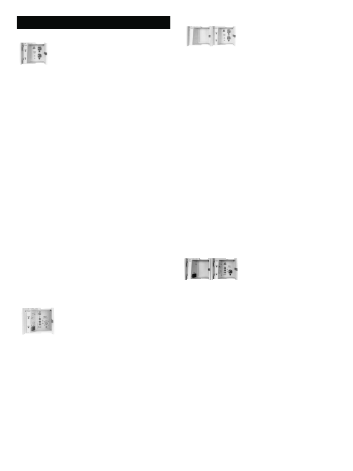
Model E411
EFT/Noise Burst simulator for testing in accordance
with IEC 61000-4-4 Edition 2 to 4.4kV.
±20% of setting
1 to 240 min.; 1 min. resolution
1 to 24 hours; 1 hour resolution
1 to 240 min.; 1 min. resolution
1 to 24 hours; 1 hour resolution
plug-in module (if no other half-width
module is ordered)
KeyTek ECAT Model E421
EFT/Noise™Burst Simulator for IEC 61000-4-4 Edition 2
to 8kV
ELECTRICAL
Burst Polarity Positive, negative, alternating
Burst Voltage 200V to 8.0kV, ±10%; 5V resolution
Burst Frequency Adjustable from 1kHz to 1MHz up to 4.4kV;
1kHz to 250kHz from 4.4kV to 8.0kV
Burst Duration 1.0ms to 20ms; 1.0ms resolution
Period Between Bursts Adjustable from 300ms to 5s; 1ms resolution
Burst Test Length 1 to 360 sec.; 1 sec. resolution
1 to 240 min.; 1 min. resolution
1 to 24 hours; 1 hour resolution
Wait Time Between Tests 1 to 360 sec.; 1 sec. resolution
1 to 240 min.; 1 min. resolution
1 to 24 hours; 1 hour resolution
Voltage Monitor Built-in; 150MHz bandwidth
Minimum System Requirements E100 series control center
Coupler/decoupler See Model E455X
Options E421-2MHz - increases EFT burst frequency to
2MHz @ </= 3kV
E421-CH - adds Chirp
CCL4/S - capacitive coupling clamp per IEC 61000-4-4
Note: For any combination of frequency, duration and period, the number of pulses can
not exceed 600 per second and 200 per burst.
Note: For any combination of frequency, duration and period, the number of pulses cannot
exceed 600 per second and 200 per burst.
Options E411-2MHz - increases EFT burst frequency to
2MHz @ </= 3kV
E411-CH - adds Chirp
CCL4/S - capacitive coupling clamp per IEC 61000-4-4
KeyTek ECAT®Model E412
EFT/Noise Burst simulator with built-in, single phase AC mains
coupler/decoupler for testing in accordance with IEC 61000-4-4
Edition 2 to 4.4kV
Model E412 features all Specifications and Options
noted in Model E411 (please see above)
PLUS:
COUPLER/DECOUPLER
Coupling Capacitors 33nf per line
Voltage 0-277/250* AC rms or DC
Current 16A continuous*
Coupling Modes Software selectable
Line Sync Software selectable 0-360°
Line Sync Accuracy ±15°
KeyTek ECAT Model E422
EFT/Noise™ Burst Simulator with built-in, single phase
AC mains coupler/decoupler for IEC 61000-4-4 Edition
2 to 8kV
Model E422 features all Specifications and Options noted in Model E421 (please
see above)
PLUS:
COUPLER/DECOUPLER
Coupling Capacitors 33nf per line
Voltage 0-250 V DC or AC rms
Current 16A continuous (actual AC line current capability
may be reduced if a connector style having a lower
current rating is chosen)
Coupling Modes Software selectable
Line Sync Software selectable 0-360°
Line Sync Accuracy ±15°
Minimum System Requirements E100 series control center
Minimum System Requirements E100 Series control center with blank
plug-in module (if no other half-width
module is ordered)
*The actual AC mains voltage and current limit is based on the mains connector selected.
Page 3
SURGE SIMULATOR MODULES
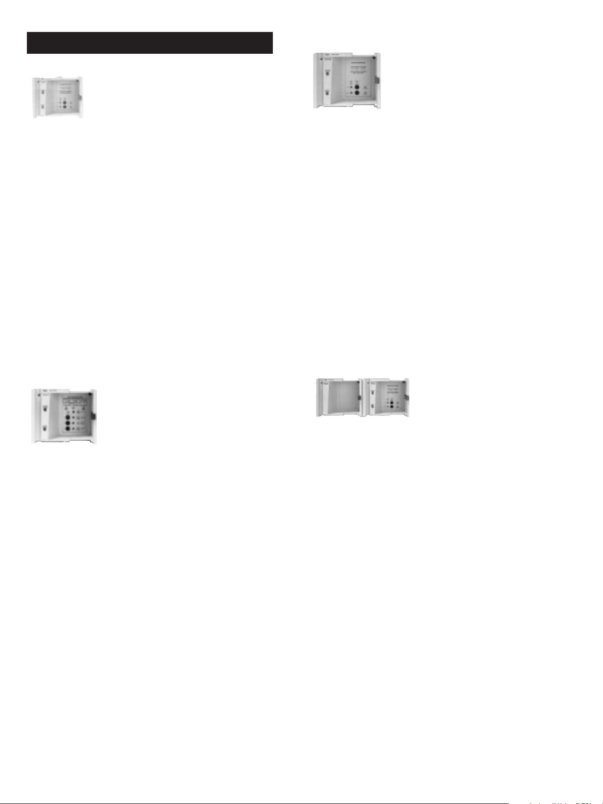
KeyTek ECAT®Model E501B
Plug-in combination wave surge simulator to produce the
combination waves required by IEC 6100-4-5, ANSI/IEEE
C62.41 Cat. B and UL 1449 (8/98) at 3kA
KeyTek ECAT®Model E503
Plug-in module to produce the ring waves specified by
ANSI/IEEE C62.41 Cat. A and B, and various UL standards,
including UL 864
ELECTRICAL
Open-Circuit Voltage 1.2/50µs, 200V - 6.6kV -5 +10% in 1 volt steps
Short-Circuit Current 8/20µs, 100A - 3.3kA -0 +10% with 2 ohm effective
source impedance. With a 12 ohm effective
source impedance, the peak short-circuit current =
open-circuit voltage ÷ 12
Rise Time Tolerance ±30% for voltage; ±20% for current
Duration Tolerance ±20%
Note: When used with a three-phase coupler/decoupler, the voltage waveform durations
may be reduced when coupling with multiple lines to PE.
Surge Repetition Rate 1 shot/12 seconds
Line Sync Accuracy ±15° with optional coupler/decoupler
Minimum System Requirements E100 Series control center with blank
plug-in module (if no other half-width
module is ordered)
Options E501B-VI - adds voltage and current monitoring
KeyTek ECAT®Model E502B
Plug-in module to produce the telecommunications surge wave
required by IEC 61000-4-5, FCC Part 68 and ITU Rec K.17, K.20,
and K.21 (formerly CCITT)
WAVEFORMS
Voltage Rise Time 0.5µs ±30%
Ringing Frequency 100kHz ±20%,
40% decay per peak
Open-Circuit Voltage 200V - 6.6kV ± 10%
Short-Circuit Current Selectable at 200A max. or 500A max., when the
open-circuit voltage is set to 6.0kV. (Actual shortcircuit current at other voltage settings will be
open-circuit voltage ÷ 30 when 200A is selected
and open-circuit voltage ÷ 12 when 500A is selected.)
Surge Repetition Rate 1 shot/9 seconds
Line Sync accuracy ±15º with optional coupler/decoupler
Minimum System Requirements E100 Series control center with blank
plug-in module (if no other half-width
module is ordered)
Options E503-VI - adds voltage and current monitoring
KeyTek ECAT®Model E504A
Plug-in module to produce the combination wave
required by UL 1449 (some devices must also be tested
using the E501A surge module)
ELECTRICAL
Open-Circuit Voltage 10/700µs and 0.5/700µs, 200V - 6.6kV ±10% in 1
volt steps.10/700µs waveform meets both IEC
and FCC Part 68 9/720µs requirements. Tighter
tolerances for front time and duration ensure
compliance with both requirements
Short-Circuit Current Open-circuit voltage ÷ 15 with 0 ohm effective
source impedance; open-circuit voltage ÷ 40 with
25 ohm effective source impedance. Tolerance is
-0/+10%
Front time tolerance Voltage: 7.0µs to 11.7µs
Current: 5.0µs ±30%
Duration Voltage: 576µs to 840µs
Current: 320µs ±20%
Surge Repetition Rate 1 shot/18 seconds
Minimum System Requirements E100 Series control center with blank
plug-in module (if no other half-width
module is ordered)
Options E502B-VI - adds voltage and current monitoring
WAVEFORMS
Open-Circuit Voltage 1.2/50µs, 0 - 6.6kV ±5% in 1 volt steps
Short-Circuit Current 8/20ms, selectable at 125A, 500A and 750A ±10%
when the open-circuit voltage is set to 6.0kV.
(Actual short-circuit current = open-circuit voltage ÷
48 when 125A is selected; open-circuit voltage ÷ 12
when 500A is selected, and open-circuit voltage = 8
when 750A is selected.)
Front Time Tolerance ±30% for voltage; ±20% for current
Duration Tolerance ±20% (Note: When used with an AC mains coupler
/decoupler, open-circuit voltage wave durations may
be significantly reduced when certain coupling
modes are selected.)
Surge Repetition Rate 1 shot/12 seconds
Line Sync Accuracy ±15º with optional AC mains: coupler/decoupler
Minimum System Requirements E100 series control center
Options E504A-VI - adds voltage and current monitoring
Page 4

KeyTek ECAT®Model E505A
Plug-in module that produces the lightning surge
waveforms required by FCC Part 68
KeyTek ECAT®Model E508 and E508-12P
ELECTRICAL
Waveforms <10/>160µs, 50-1650V ±10%; peak short-circuit
current is 200A, -0% +10% when the open-circuit
voltage is set to 1500V
<10/>560µs, 50-880V ±10%; peak short-circuit
current is 100A, -0% +10% when the open-circuit
voltage is set to 800V
<2/>10µs, 100-2750V ±10%; peak short-circuit
current is 1000A, -0% +10% when the open-circuit
voltage is set to 2500V
Note: All voltage and current specifications are
minimum values in accordance with FCC Part 68
Surge Repetition Rate 1 shot/18 seconds for all waves except <2/>10µs
which is 1 shot/24 seconds
Line Sync Accuracy ±15º with optional coupler/decoupler
Minimum System Requirements E100 series control center
Options E505A-VI - adds voltage and current monitoring
KeyTek ECAT®Model E506-4W
Plug-in module to produce the 2/10µs surges required by
Telcordia GR-1089 CORE for up to five-wire (four terminal)
testing
Plug-in modules to produce the 10/360µs surges required by Telcordia GR-1089 CORE
E508 WAVEFORMS
Open-Circuit Voltage 10/360µs, 50-1100V, -0/+15% in 1 volt steps.
Tip and ring outputs independent and isolated to
ensure true, three-terminal simultaneous testing of
up to 12 pair. Waveforms as defined by Telcordia
GR-1089-CORE
Short-Circuit Current 100A/side -0/+15% at a voltage setting of 1.0kV
Front Time Tolerance -30/+0% for voltage and current
Duration Tolerance -0/+30%
Surge Repetition Rate 1 shot/50 seconds
E508-12P WAVEFORMS
Open-Circuit Voltage 10/360µs, 50-1100V, -0/+15% in 1 volt steps.
Tip and ring outputs independent and isolated to
insure true, three-terminal simultaneous testing of
up to 12 pair. Waveforms as defined by Telcordia
GR-1089-CORE.
Short-Circuit Current 25A/side -0/+15% at a voltage setting of 1.0kV
Front Time Tolerance -25%/+0 for voltage; -30%/+0 for current
Duration Tolerance -0/+30%
Surge Repetition Rate 1 shot/150 seconds
ELECTRICAL
Waveforms <2/>10µs, 50-800V, 100A/terminal with 800V open-
circuit voltage
<2/>10µs, 50-1500V, 100A/terminal with 1500V
open-circuit voltage
<2/>10µs, 100-2500V, 500A/terminal with 2500V
open-circuit voltage
<2/>10µs, 200-5000V, 500A/terminal with 5000V
open-circuit voltage
Tolerances All peak open-circuit voltages and short-circuit
currents are -0%/+20%
Outputs Front panel terminals for connection to T1, R1, T2,
R2 and Ground
Surge Repetition Rate: 1 shot/16 seconds
Minimum System Requirements E100 series control center
Options E506-4W-VI - adds voltage and current monitoring
Minimum System Requirements E100 series control center
Options E508-VI - adds voltage and current monitoring
Page 5

KeyTek ECAT®Model E510A
Plug-in module to produce combination wave specified
by ANSI/IEEE C62.41 Cat. B and IEC 61000 4-5 to 10kV
and 5kA
Electrical Open-Circuit Voltage 1.2/50µs, 0-10.1kV ±10% in 1 volt steps
KeyTek ECAT®Model E513
Plug-in module to produce voltage ramps for testing surge protection components such as gas tube arrestors; meets surge
simulator requirements of UL 864
Short-Circuit Current 8/20µs, 0-5.05kA with 2 ohm effective source
impedance, ±10%
With the additional 10 ohm resistor, the peak short-circuit current = open-circuit voltage
÷12, ±10%. (The short-circuit current waveform is modified by the additional resistance.)
Front Time Tolerance ±30% for voltage
±20% for current
Duration Tolerance ±20% voltage and current
Surge Repetition Rate 1 shot/18 seconds
Line Sync Accuracy +15º with optional coupler/decoupler
Compatible Powerline E455x-kV, E4555, E4556
Coupler/Decouplers
Minimum System Requirements E100 series control center
Options E510A-VI - adds voltage and current monitoring
KeyTek ECAT®Model E511
Plug-in module to provide combination waves to 6 kV and 5kA,
as required by British Telecom standards
ELECTRICAL
Open-Circuit Voltage 1.2/50µs, 200V to 6.6kV ±5% in 1 volt steps
WAVEFORMS
Voltage Ramps 0.1kV/µs, 0.5kV/µs, 1.0kV/µs, 5.0kV/µs, 10kV/µs,
0.1kV/µs is linear to 2.5kV; all other ramps linear to
3.0kV
Note: Specified ramp rates are obtained with an open-circuit voltage setting of 3.0kV.
Voltage Durations ~65µs for 0.1kV/µs; ~40µs for 0.5kV/µs and 1kV/µs;
~5µs for 5kV/µs and 10kV/µs
Current Durations ~45µs at 0.1kV/µs; ~40µs at 0.5kV/µs and 1.0kV/µs;
~5µs at 5kV/µs and 10kV/µs
Open-Circuit Voltage 0-3000V; ±5% in 1 volt steps
Short-Circuit Current 50A, ±10% when the peak open-circuit
voltage is set to 3.0kV
Minimum System Requirements E100 series control center
Options E513-VI - adds voltage and current monitoring
NOTE: To obtain linear fronts, waves are quasi-square waves with 20-25% initial
overshoots beyond peak open-circuit voltages, except for the 0.1kV/µs which is roughly
triangular. Undershoots range from 5 to 25%
KeyTek ECAT®Model E514
Surge simulator for 10/1000µs current waves
Short-Circuit Current 8/20µs, 170A to 5.5kA with 1.2 ohm effective
source impedance, ±10%
Front Time Tolerance ±30% for voltage
±20% for current
Duration Tolerance ±20% voltage and current
Surge Repetition Rate: 1 shot/12 seconds
Line Sync Accuracy ±15º with optional coupler/decoupler
Minimum System Requirements E100 Series control center with blank
plug-in module (if no other half-width
module is ordered)
Options E511-VI - adds voltage and current monitoring
WAVEFORMS
Open-Circuit Open-circuit voltage waveforms
Voltage Vary according to the peak
short-circuit current level selected:
Peak I Open-Circuit V
15A 10/1000µs, 50-1650V ±10%
60A 1kV/µs linear ramp, 50-1650V
100A 10/1000µs, 50-1000V
250A 1kV/µs linear ramp, 50-1650V ±10%
Short-Circuit Current 10/1000µs; software selectable at 15A,
60A, 100A, and 250A, ±10%
Rise Time Tolerance ±30%
Duration Tolerance ±20%
Surge Repetition Rate 15A, 60A - 1 shot/21 seconds
100A, 250A - 1 shot/59 seconds
Minimum System Requirements E100 series control center
Options E514-VI: Provides monitoring of the peak surge
voltages and currents at the output of the E514
module. All measurements are logged by software
for diagnostic evaluation or Go/No-Go testing.
Note: If a KeyTek ECAT coupler/decoupler is
included, waveform monitoring is available at the
output of the coupler/decoupler without the addition
of KeyTek E514-VI option
Page 6

KeyTek ECAT®Model E515
Module to produce the 10/250µs surges required by
Telcordia GR-1089-CORE
ELECTRICAL
Waveform <10/>250µs, 200-4000V -0/+16% peak open-circuit
voltage; 100-2000A
-0/+16% peak short circuit-current.
Front Time Tolerance -60%/+0 for voltage;
-30%/+0 for current
Duration Tolerance -0/+60% for voltage;
-0/+20% for current
Surge Repetition Rate 1 shot/126 seconds 0 to 4kV range
1 shot/63 seconds 0 to 2kV range
Minimum System Requirements E100 series control center
Options E515-VI - adds voltage and current monitoring
KeyTek ECAT®Models E521 and E522
Surge systems that produce the high voltage, high current combination
waves required by ANSI standards for service entrance and outside
connected electronics; meets requirements of IEC 61000-4-5 for all exposure categories. ECAT Model E521includes built-in AC coupler/decoupler
for single-phase lines to 480V, 32A; ECAT Model E522includes built-in AC
coupler/decoupler for three-phase lines to 480V, 32A/phase (actual AC
mains current per AC line connector limits).
ELECTRICAL
Open-Circuit Voltage 1.2/50µs, 200V to 20.2kV ±10%
Short-Circuit Current 8/20µs, 100A to 10.1kA ±10%, with 2 ohm
effective source impedance. With a 12 ohm
effective source impedance, the peak short-circuit
current = open-circuit voltage ÷ 12
Rise Time Tolerance ±30% for voltage;
±20% for current
Duration Tolerance ±20% for voltage and current
Surge Repetition Rate 1 shot/30 seconds @ <=10kV
1 shot/minute @ >10kV
Line Sync Accuracy: ±5°
KeyTek ECAT®Model E518
Plug-in module to produce the 10/1000µs waveform to 2000V as
required by Telcordia GR-1089-CORE for Protection Coordination.
Includes HB-ECAT.
ELECTRICAL
Waveforms 10/1000µs, 50-600V -0/+15% peak open-circuit
voltage; 100A/side
-0/+15% peak short-circuit current
10/1000µs, 50-1000V -0/+15% peak open-circuit
voltage; 100A/side
-0/+15% peak short-circuit current
10/1000µs, 50-2000V -0/+15% peak open-circuit
voltage; 100A/side @ 1kV; 200A/side @ 2kV
-0/+15% peak short-circuit current
NOTE: All voltage and current specifications are minimum values, in accordance with
Telcordia GR-1089-CORE
Outputs are all true three-terminal outputs for testing either two or three-terminal devices
or inputs. Outputs can be connected in parallel to double the available peak short-circuit
current when testing two-terminal devices.
Front time tolerance -30%/+0%
Duration tolerance -0/+50%
Surge repetition rate 1 shot/40 seconds at 600V and 1kV; longer charging
times at higher voltages
Minimum System Requirements: E100 series control center
Options E518-VI - adds voltage and current monitoring
Minimum System Requirements: E100 series control center
Options E521-VI - adds 3-wire VI monitoring plus automatic
software selection to Model E521
E522-VI - adds 5-wire VI monitoring plus automatic
software selection to Model E522
SURGE COUPLER/DECOUPLERS
KeyTek ECAT®Model E551
A single-phase AC line (power lines) coupler/decoupler for surge waves,
as specified by IEC 61000-4-5.
ELECTRICAL
Voltage 250V rms AC, single-phase
Current 16A continuous with appropriate connectors (i.e.
Schuko or other) 15A continuous with NEMA 5-15
style connector used in the U.S.A.
Coupling Mode Selection Coupling mode selection is programmable -
manually from the control center, or automatically
using KeyTek SurgeWare
Monitoring Monitoring and peak detection of surge voltage
across any two manually-selected lines. Monitoring
can be at the EUT or at the front panel of the
coupler/decoupler.
Monitoring and peak detection of surge current in
either High or Neutral, selected by the ECAT Control
Center or the computer, measured without including
back-filter surge current.
Minimum System Requirements: E100 series control center
Options E551-DC - allows use of surge coupler/decouplers
on DC power mains
™
software.
Page 7

COMBINED SURGE & EFT COUPLER/DECOUPLERS
PQF™(POWER QUALITY FAILURE) MODULES
KeyTek ECAT®Model E455x
Single and three-phase AC line coupler/decouplers for EFT
and Surge waves, as specified by IEC 61000-4-4 and IEC
61000-4-5
ELECTRICAL
Model Single or Three-phase Voltage Current** per phase
E4551A/E4551kV* Single-phase 250V rms 15/16A***
E4552A/E4552kV* Single-phase 277V rms 32A
E4553A/E4553kV* Three-phase 480V rms 16A
E4554A/E4554kV* Three-phase 480V rms 32A
E4555 Three-phase 600V rms 50A
E4556 Three-phase 600V rms 100A
* kV version is required for operation with surge modules greater than 7kV, such as the
E510A. All standard coupler/decoupler options apply
** Actual current capability may be limited by the AC line connectors selected
*** Depends on connector selected. Typically 15A with U.S. NEMA connector; 16A with
appropriate European style connectors
Coupling Mode Coupling mode selection is controlled manually from the control
Selection center, or automatically using KeyTek SurgeWare™ or
BurstWare™software. Coupling is allowed from any line to any
other line or combination of lines.
Monitoring Monitoring and peak detection of surge voltage across any two
manually-selected lines. Monitoring can be at the EUT or at the
front panel of the coupler/decoupler.
Monitoring and peak detection of surge current in either High or Neutral, selected by the
ECAT Control Center or the computer, measured without including back-filter surge current.
Minimum E100 series control center EFT or mains - coupled surge module
Requirements
Options
E455x-DC Allows the E455x coupler/decoupler to be used with DC as well as
AC mains. The DC current ratings for essentially resistive loads are:
to 48V to 110 V to 220V
E4551A/E4551kV 15A 5A 0.8A
E4552A/E4552kV 15A 5A 0.8A
E4553A/E4553kV 20A 8A 1.2A
E4554A/E4554kV 25A 8A 1.2A
E4555 50A 50A (120V) 30A
E4556 100A 50A (120V) 30A
E455x-VI Enhanced V and I monitoring. Adds monitoring and peak detection of
Surge voltage and current. Upper and lower limits can be placed on
surge peaks. Monitoring of 3 wires is provided in single-phase
systems, 5 wires in three-phase systems. Selection of the V and I
inputs is performed from the control center or can be made
automatically with SurgeWare control software
E455x-HV Increases the AC mains voltage rating from 277V to 480V rms in the
E4552, and from 480V to 600V rms in the E4553 and E4554. The HV
option is not available in the E4551, E4555 and E4556.
Physical Physical size of module varies depending on model number
KeyTek ECAT Models EP61 and EP62
Plug-in modules provide swells, dips and interrupts on AC
power mains in compliance with, and exceeding the
requirements of IEC 61000-4-11 Edition 2. Model EP61 for
single-phase AC lines to 240 RMS, 16A; Model EP62 for
single-phase AC lines to 240 RMS, 32A
AC INPUTS/OUTPUTS
Input Voltage for 100% 50 to 240V at 50Hz and to 277V at 60Hz
Output Voltages on 0% (open or short), 40%, 50%, 70%,
the Selected Phase 80%, 90%, 100%, 110%, 120% and 150%
EP61 Output Current 16A at 250V; 20A at 125V*
EP62 Output Current 32A at 250V; 30A at 125V*
*The actual AC mains voltage and current limit is based on the mains connector selected.
Inrush Current >250A at 120V; >500A at 220-240V
Event Duration from 0.03 cycle (10°) to 500 minutes;
maximum 12 events per cycle
Switching Times 1-5µs into a 100 ohm load
Overshoot <5%
Undershoot <5%
MEASUREMENTS
rms Voltage 0-300V, 0.5% of range + 1% of reading
rms Current 0-40A, 0.5% of range + 1% of reading
Peak Current 0-1000A, 1% of range + 5% of reading
Inrush Current Qualification Internal, built-in circuit according to
IEC 61000-4-11. Automatically measures peak
inrush current at 90° and 270°. Peak values are
reported via the control software.
Minimum System Requirements: E100 series control center
Page 8

Single Source, Total EMC Test Solutions
Experience the many benefits of working with recognized experts in the field of EMC (Electromagnetic Compatibility)
testing. Our commitment to the discipline is wide ranging; we actively participate on global standards committees, and
have helped define test methodologies to achieve regulatory standards such as CE Mark requirements, as well as
company and market-driven product quality objectives,.
Our goal is to support you with lifelong service — from applications support, calibration services and preventative
maintenance scheduling to full tactical field support.
Thermo can help you reach the next level of success.
For KeyTek ECAT bundled test systems designed to fully address Telecordia GR-1089-CORE (Telecom & Broadband),
UL1449 (Transient Voltage Surge Suppressors), UL864 & others (Product Safety), and FCC Part 68 standards, please
refer to the KeyTek ECAT Bundled Test Systems brochure.
Please also see the KeyTek EMC Test System Options & Accessories data sheet for additional KeyTek ECAT test
system options and accessories.
Specialists who understand the challenges you face. Innovative ideas. Leading technologies. Breadth of EMC test equipment.
Thermo–your EMC test solutions partner. Contact us today for details.
This sheet is for informational purpose only and is subject to change without notice.
© 2004 Thermo Electron Corporation. All rights reserved. Thermo Electron Corporation, Question everything, and Analyze. Detect. Measure. Control.
are trademarks of Thermo Electron Corporation.
Control Technologies Division One Lowell Research Center (978) 275-0800 www.thermo.com/esd
Lowell, MA, 01852 (978) 275-0850 fax
Formerly doing business as Thermo KeyTek
 Loading...