

Page 1

DSP-100/2000
LAN CableMeter®/Cable Analyzer
®
PN 642964
January 1997
© 1997 Fluke Corporation. All rights reserved. Printed in U.S.A.
All product names are trademarks of their respective companies.
Users Manual
Page 2

LIMITED WARRANTY & LIMITATI O N OF LIABILITY
Each Fluke product is warranted to be free from defects in material and workmanship under normal use and
service. The warranty period is one year and begins on t he date of shipment. Parts, product repai rs and
services are warranted for 90 days. This warranty extends only to the original buyer or end-user customer of a
Fluke authorized reseller, and does not apply to fuses, disposable batteries or to any product which, in Fluke’s
opinion, has been misused, altered, negl ected or damaged by accident or abnormal conditions of operation or
handling. Fluke warrants that software will operat e substantially in accordance with it s functional specifications
for 90 days and that it has been properly recorded on non-def ective media. Fluke does not warrant that software
will be error free or operate without interruption.
Fluke authorized resellers shall extend this warranty on new and unused products to end-user customers onl y
but have no authority to extend a greater or di f ferent warranty on behalf of Fluke. Warrant y support is available if
product is purchased through a Fluke authorized sales out l et or Buyer has paid the applicable internati onal pri ce.
Fluke reserves the right to invoice Buyer f or i m portation costs of repair/replacement part s when product
purchased in one country is submitted f or repai r i n another country.
Fluke’s warranty obligation is l i mited, at Fluke’s option, t o refund of the purchase price, free of charge repair, or
replacement of a defective product which is returned to a Fluke authorized service center within the warranty
period.
To obtain warranty service, contact your nearest Fl uke aut hori zed servi ce center or send the product, with a
description of the difficult y, postage and insurance prepaid (FOB Destination), t o the nearest Fluke authorized
service center. Fluke ass umes no risk for damage in transit. Following warranty repair, the product will be
returned to Buyer, transportation prepaid (FOB Destination). If Fluke determ i nes that the failure was caused by
misuse, alteration, accident or abnormal condition of operation or handling, Fluke will provide an estimate of
repair costs and obtain authorization bef ore c ommencing the work. Following repair, the product will be returned
to the Buyer transportation prepaid and the Buyer will be billed for the repair and return transportation charges
(FOB Shipping Point).
THIS WARRANTY IS BUYER’S SOLE AND EXCLUSIVE REMEDY AND IS IN LIEU OF ALL OTHER
WARRANTIES, EXPRESS OR IMPLIED, INCLUDING BUT NOT LIMITED TO ANY IMPLIED WARRANTY OF
MERCHANTABILITY OR FITNESS FOR A PARTICULAR PURPOSE. FLUKE SHALL NOT BE LIABLE FOR
ANY SPECIAL, INDIRECT, INCIDENTAL OR CONSEQUENTIAL DAMAGES OR LOSSES, INCLUDING LOSS
OF DATA, WHETHER ARISING FROM BREACH OF WARRANTY OR BASED ON CONTRACT, TORT,
RELIANCE OR ANY OTHER THEORY.
Since some countries or states do not allow limitation of the term of an implied warranty, or exclusion or
limitation of incidental or consequential damages, the limitat i ons and exclusions of this warranty m ay not apply to
every buyer. If any provision of t hi s Warranty is held invalid or unenforceable by a court of competent
jurisdiction, such holding will not affect the validity or enforceability of any other provision.
Fluke Corporation Fluke Europe B.V.
P.O. Box 9090 P.O. Box 1186
Everett, WA 98206-9090 5602 BD Eindhoven
U.S.A. The Netherlands
5/94
Page 3

Table of Contents
Chapter Page
1 Introduction...................................................................................... 1-1
Overview of Features...................................................................................... 1-1
Standard Accessories ...................................................................................... 1-3
Using This Manual.......................................................................................... 1-5
2 Getting Started................................................................................. 2-1
W Safety and Operational Information.......................................................... 2-1
Quick Start....................................................................................................... 2-3
Quick Configuration........................................................................................ 2-4
Results within Accuracy Range...................................................................... 2-6
Autotest on Twisted Pair Cable ...................................................................... 2-7
Autotest on Coaxial Cable .............................................................................. 2-10
Main Unit Features.......................................................................................... 2-12
Remote Features.............................................................................................. 2-14
Strap and Bail.................................................................................................. 2-16
Rotary Switch.................................................................................................. 2-16
Turning On the Test Tool................................................................................ 2-20
Configuring the Test Tool............................................................................... 2-22
Remote Lights, Messages, and Audible Tones............................................... 2-29
Remote End Testing........................................................................................ 2-30
Remote Communication Error........................................................................ 2-31
Battery Status.................................................................................................. 2-31
3 Autotest............................................................................................ 3-1
Autotest Softkeys............................................................................................ 3-1
Autotest on Twisted Pair Cable ...................................................................... 3-2
Link Performance Grade Result (Headroom)................................................. 3-4
Automatic Diagnostics (Model DSP-2000).................................................... 3-4
Autotest Results for Twisted Pair Cable......................................................... 3-6
i
Page 4

DSP-100/2000
Users Manual
Autotest on Coaxial Cable.............................................................................. 3-19
Autotest Results for Coaxial Cable ................................................................ 3-21
Saving Autotest Results.................................................................................. 3-23
The Autotest Report........................................................................................ 3-25
4 Running Individual Tests ................................................................ 4-1
Single Tests for Twisted Pair Cable............................................................... 4-1
Scanning Function.......................................................................................... 4-2
When to Use a Remote Unit........................................................................... 4-2
The TDX Analyzer ......................................................................................... 4-6
The TDR Test ................................................................................................. 4-9
Single Test Results for Twisted Pair Cable.................................................... 4-12
Single Tests for Coaxial Cable....................................................................... 4-14
Monitoring Network Activity......................................................................... 4-16
Identifying Hub Port Connections.................................................................. 4-20
Monitoring Impulse Noise.............................................................................. 4-20
Determining Hub Port Capabilities (Model DSP-2000)................................. 4-23
Using the Tone Generator (Model DSP-2000)............................................... 4-24
5 Viewing and Printing Saved Reports.............................................. 5-1
Printing Test Reports...................................................................................... 5-1
Viewing, Renaming, and Deleting Test Reports............................................ 5-6
6 Calibrations and Custom Test Standards...................................... 6-1
Calibrating the Test Tool................................................................................ 6-1
NVP Calibration ............................................................................................. 6-3
Configuring a Custom Cable.......................................................................... 6-4
7 Basic Cable Testing......................................................................... 7-1
LAN Cable Construction................................................................................ 7-1
Attenuation ..................................................................................................... 7-5
Noise .............................................................................................................. 7-6
Characteristic Impedance................................................................................ 7-7
Crosstalk and Near-End Crosstalk (NEXT) ................................................... 7-9
Nominal Velocity of Propagation (NVP)....................................................... 7-14
Time Domain Reflectometry (TDR)............................................................... 7-15
ACR .............................................................................................................. 7-19
RL .............................................................................................................. 7-20
Troubleshooting Basics .................................................................................. 7-21
8 Maintenance and Specifications..................................................... 8-1
Maintenance.................................................................................................... 8-1
If the Test Tool Fails ...................................................................................... 8-4
Specifications.................................................................................................. 8-7
ii
Page 5

Contents
(continued)
Appendices
A Using DSP-LINK ................................................................................. A-1
B Glossary................................................................................................ B-1
C Tests Run per Test Standard During an Autotest................................. C-1
Index
iii
Page 6

DSP-100/2000
Users Manual
iv
Page 7

List of Tables
Table Page
2-1. International Electrical Symbols................................................................. 2-1
2-2. Key Functions for the Menu System .......................................................... 2-3
2-3. Quick Configuration Settings..................................................................... 2-4
2-4. Main Unit Features ..................................................................................... 2-13
2-5. Remote Connectors and Features ............................................................... 2-15
2-6. Status Indications from Remotes................................................................ 2-29
2-7. Battery Status Messages ............................................................................. 2-31
3-1. Wire Map Displays..................................................................................... 3-6
3-2. Items on the Attenuation Results Screen.................................................... 3-10
3-3. Items on the Attenuation Plot Screen ......................................................... 3-11
3-4. Items on the NEXT Results Screen ............................................................ 3-12
3-5. Items on the NEXT Plot Screen.................................................................. 3-13
3-6. Items on the ACR Results Screen............................................................... 3-15
3-7. Items on the ACR Plot Screen.................................................................... 3-16
3-8. Items on the RL Results Screen.................................................................. 3-17
3-9. Items on the RL Plot Screen....................................................................... 3-18
3-10. Items on the Autotest Save Screen.............................................................. 3-24
4-1. Remote Requirements for Cable Tests....................................................... 4-3
4-2. Items on the TDX Analyzer Results Screen............................................... 4-7
4-3. Items on a TDX Analyzer Plot.................................................................... 4-8
4-4. Effects of Termination on TDR Results..................................................... 4-9
4-5. Items on the TDR Results Screen (Twisted Pair Results).......................... 4-11
4-6. Items on the TDR Plot (Twisted Pair Results) ........................................... 4-12
4-7. Items on the Traffic Monitor Screen........................................................... 4-19
4-8. Items on the Noise Monitor Screen ............................................................ 4-23
7-1. Identifying Cable Faults.............................................................................. 7-22
8-1. Troubleshooting the Test Tool.................................................................... 8-5
8-2. Replacement Parts....................................................................................... 8-6
8-3. Characteristic Impedance Test Specifications............................................ 8-8
8-4. Length Test Specifications ......................................................................... 8-9
8-5. Length Test Specifications ......................................................................... 8-9
v
Page 8

DSP-100/2000
Users Manual
8-6. Distance Specifications for TDR Test........................................................ 8-11
8-7. PC Interface Cable Connections................................................................. 8-13
8-8. 9-to 25-pin Adapter.................................................................................... 8-13
8-9. Certifications.............................................................................................. 8-16
A-1. Summary of DSP-LINK Functions ............................................................ A-5
A-2. Special Terms Used in DSP-LINK............................................................. A-6
A-3. Formats for Uploaded Reports................................................................... A-7
C-1. Tests Run per Test Standard During an Autotest....................................... C-2
vi
Page 9

List of Figures
Figure Page
1-1. Standard Accessories.................................................................................. 1-4
2-1. The Asterisk and Test Tool Accuracy ........................................................ 2-6
2-2. Autotest Connections for Twisted Pair Cable (Channel) ........................... 2-8
2-3. Autotest Connections for Coaxial Cable .................................................... 2-11
2-4. Main Unit Features ..................................................................................... 2-12
2-5. Standard and Smart Remote Features......................................................... 2-14
2-6. Attaching the Strap and Opening the Bail.................................................. 2-16
3-1. Autotest Connections for Twisted Pair Cable (Basic Link)....................... 3-2
3-2. Examples of Automatic Diagnostics Displays............................................ 3-5
3-3. The Attenuation Plot Screen....................................................................... 3-11
3-4. The NEXT Plot Screen ............................................................................... 3-13
3-5. The ACR Plot Screen.................................................................................. 3-16
3-6. The RL Plot Screen..................................................................................... 3-18
3-7. Autotest Connections for Coaxial Cable .................................................... 3-21
3-8. Screen for Saving Autotest Results ............................................................ 3-24
3-9. Part of an Autotest Report for Twisted Pair ............................................... 3-26
3-10. Autotest Report for Coaxial Cable ............................................................. 3-27
3-11. Autotest Report Summary........................................................................... 3-27
4-1. Single Test Connections for Twisted Pair Cable........................................ 4-4
4-3. Example of a TDX Analyzer Plot for a Good Twisted Pair Cable Run..... 4-8
4-3. Example of a TDR Plot (Twisted Pair Results).......................................... 4-12
4-4. Single Test Connections for Coaxial Cable................................................ 4-15
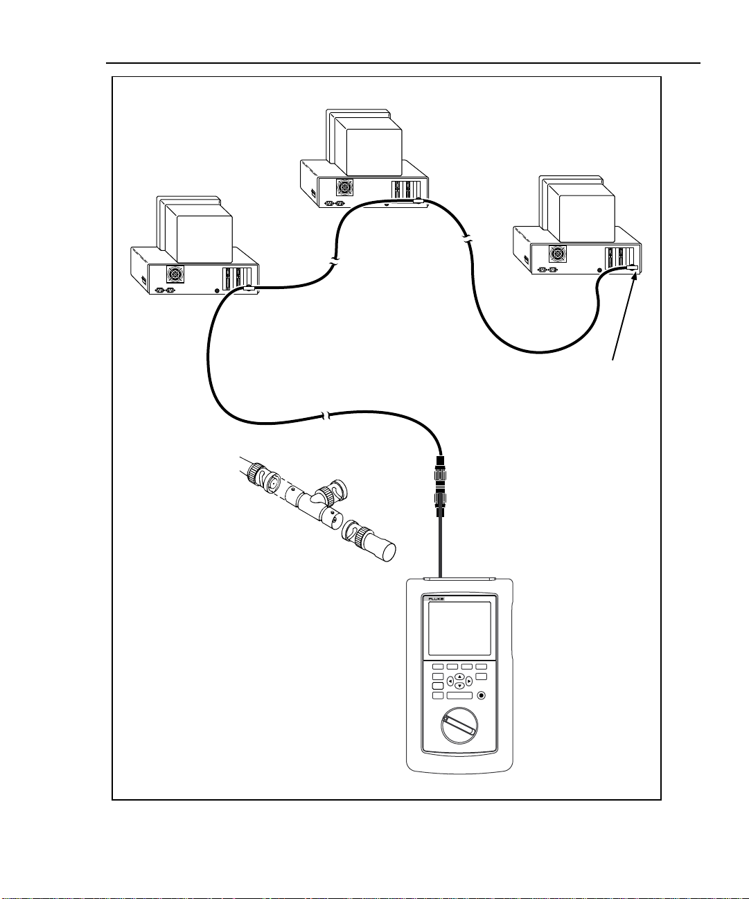
4-5. Connections for Monitoring Network Traffic ............................................ 4-17
4-6. Connections for Monitoring Impulse Noise............................................... 4-21
5-1. Connections for Printing Test Reports ....................................................... 5-3
6-1. Connections for Self-Calibration (Smart Remote Shown)......................... 6-2
7-1. Twisted Pair Cable Construction................................................................ 7-2
7-2. EIA/TIA RJ45 Connections........................................................................ 7-3
7-3. Coaxial Cable Construction........................................................................ 7-4
7-4. Attenuation of a Signal............................................................................... 7-5
7-5. Sources of Electrical Noise......................................................................... 7-6
vii
Page 10

DSP-100/2000
Users Manual
7-6. A TDX Analyzer Plot................................................................................. 7-10
7-7. Split Pair Wiring......................................................................................... 7-12
7-8. How NVP is Calculated ............................................................................. 7-14
7-9. Signals Reflected from an Open, Shorted, and Terminated Cable............. 7-16
7-10. Example of a TDR Plot.............................................................................. 7-18
7-11. A Plot of NEXT, Attenuation, and the Resulting ACR ............................. 7-20
8-1. Removing the Battery in the Standard Remote.......................................... 8-2
8-2. Removing the NiCad Battery Pack............................................................. 8-3
8-3. Operating Environment Specifications ...................................................... 8-15
A-1. Connecting the Test Tool to a PC .............................................................. A-3
viii
Page 11

Chapter 1 provides the following information:
• Features of the DSP-100 and DSP-2000 test tools.
• A list of equipment included with the test tools.
• A guide to using this manual.
Overview of Features
The Fluke DSP-100 LAN CableMeter® and DSP-2000 LAN Cable Analyzer test
tools (hereafter referred to collectively as “the test tool”) are hand-held
instruments used to certify cable and to test and troubleshoot coaxial and twisted
pair cable in local area network (LAN) installations. The test tool features new
measurement technology that combines test pulses with digital signal processing
to provide fast, accurate results and advanced testing capabilities.
Chapter 1
Introduction
The test tool includes the following features:
• Checks LAN cable performance against IEEE, ANSI, TIA, and ISO/IEC
standards.
• Presents test options and results in a simple menu system.
• Presents displays and printed reports in English, German, French, Spanish, or
Italian.
• Runs all critical tests automatically.
1-1
Page 12

DSP-100/2000
Users Manual
• Produces 2-way Autotest results in approximately 20 seconds.
• Includes a stored library of common test standards and cable types.
• Allows for configuration of up to 4 custom test standards.
• Time Domain Crosstalk (TDX) analyzer locates the position of crosstalk
(NEXT) problems on a cable.
• Tests for return loss (RL).
• Produces plots of NEXT, attenuation, ACR, and RL. Shows NEXT, ACR, and
attenuation results up to 155 MHz.
• Stores at least 500 cable test results in nonvolatile memory.
• Monitors impulse noise and network traffic on Ethernet systems. Hub port
locator helps you identify port connections.
• Sends stored test reports to a host computer or directly to a serial printer.
• Flash EPROM accepts test standard and software upgrades.
• Tests fiber optic cable when used with a Fluke DSP Fiber Optic Meter.
Model DSP-2000 includes the following additional features:
• Monitors 100BaseTX network traffic.
• Diagnostic routine provides specific information about the location and cause
of an Autotest failure.
• Tests for remote return loss (RL@REMOTE) and power sum NEXT
(PSNEXT).
• Determines which standards are supported by a hub port connection.
• Tone generator lets you use an inductive pickup device to identify cables in a
LAN installation.
1-2
Page 13

Standard Accessories
The test tool comes with the following accessories, which are shown in Figure
1-1. If the test tool is damaged or something is missing, contact the place of
purchase immediately.
1 AC/adapter/charger (2 with smart remote package) 120V (US only) or universal
adapter/charger and line cord (outside North America)
2 RJ45 2m (6.6 ft), 100Ω, straight-through patch cables
1 RJ45 15 cm (6”), 100Ω, straight-through patch cable
1 50Ω BNC coaxial cable
1 RJ45 to BNC adapter (Model DSP-2000 only)
1 PC serial interface (EIA-232C) cable
1 Carrying strap (2 with smart remote package)
1 3.5” DSP-LINK utility diskette
1 Users manual (not shown)
1 Warranty registration card (not shown)
1 Soft carrying case for Model DSP-100 (2 with smart remote package, not shown.
Discard loose foam pieces.)
1 Smart remote unit with Model DSP-2000 (not shown)
1 Hard carrying case with Model DSP-2000 (not shown)
Introduction
Standard Accessories
1
1-3
Page 14

DSP-100/2000
Users Manual
Straight Through
15 cm (1)
RJ45
Patch
2m (2)
RS-232 Cable
Strap
Coaxial
Cable
RJ45 to BNC Adapter
(DSP-2000 Only)
DSP-Link Software
3.5-Inch Floppy Disk
BP7217
Nickel-Cadmium
Battery Pack
1-4
AC Adapter/Charger
or
gc01f.eps
Figure 1-1. Standard Accessories
Page 15

Using This Manual
Before using the test tool, careful ly read "Safety and
Operational Information" at the beginning of Chapter 2.
If you are familiar with the general features, functions, and operation of LAN
cable testers and want to start testing cables immediately, proceed as follows:
1. Read “Quick Start” in Chapter 2 to prepare the test tool for operation, access
the test tool’s functions, and run an Autotest.
2. Refer to the test and setup features listed under “Rotary Switch” in Chapter 2
to locate functions in the test tool’s menu structure.
3. Refer to Appendix B, “Glossary,” to find definitions for unfamiliar terms.
If you have never used a LAN cable tester, but want to start testing cables
immediately and learn as you work, proceed as follows:
1. Read “Quick Start” in Chapter 2 to prepare the test tool for operation, access
the test tool’s functions, and run an Autotest.
2. Refer to Appendix B, “Glossary,” to find definitions for unfamiliar terms.
WWarning
Introduction
Using This Manual
1
3. Refer to the test and setup features listed under “Rotary Switch” in Chapter 2
to locate functions in the test tool’s menu structure.
4. Refer to Chapter 3, “Autotest,” to find more detailed information about cable
tests and test results.”
5. Read Chapter 4, “Running Individual Tests,” to learn how to run individual
tests and monitor network traffic and impulse noise.
6. Read Chapter 7, “Basic Cable Testing,” to add to your cable testing and
troubleshooting knowledge.
1-5
Page 16

DSP-100/2000
Users Manual
If you have never used a LAN cable tester and want to learn about cable testing
and troubleshooting before you use the test tool, proceed as follows:
1. Read Chapter 7, “Basic Cable Testing,” to learn the basics of LAN cable
characteristics, testing, and interpreting test results.
2. Read “Features” in Chapter 2 to familiarize yourself with the test tool.
3. Read “Getting Started” in Chapter 2 to learn how to prepare the test tool for
use.
4. Read Chapter 3, “Autotest,” to learn how to run the most commonly used
cable test and interpret the test results.
5. Read Chapter 4, “Running Individual Tests,” to learn how to run individual
tests and monitor network traffic and impulse noise.
6. Refer to the test and setup features listed under “Rotary Switch” in Chapter 2
to locate functions in the test tool’s menu structure.
7. Refer to Appendix B, “Glossary,” to find definitions for unfamiliar terms.
1-6
Page 17

Chapter 2
Getting Started
Chapter 2 provides the following information:
• Safety and cautions to observe when using the test tool.
• Instructions for getting started quickly with the test tool.
• Detailed information on the test tool’s features.
• Detailed instructions on configuring the test tool.
Safety and Operational Information
The international electrical symbols used on the instrument or in this manual are
described in Table 2-1.
Table 2-1. International Electrical Symbols
Warning: Risk of electric shock.
Warning or Caution: Risk of damage or destruction to equipment or software. See
explanations in the manual.
Equipment is protected by double insulation or reinforced insulation to protect the user
against electric shock.
Do not connect this terminal to public communications networks, such as telephone
systems.
Battery should be recycled. Refer to "R eplacing the NiCad Battery Pack" in Chapter 8.
2-1
Page 18

DSP-100/2000
Users Manual
XWarning
To avoid possible fire or electric shock w hen chargi ng t he
battery or powering the test tool w ith ac power, use only
the ac adapter/charger provided with the test t ool.
WCaution
Never connect the test tool to telephone l ines of any type,
including ISDN lines. Doing so can damage the test tool.
• Always turn on the test tool before connecting it to a cable. Turning the test
tool on activates the tool’s input protection circuitry.
• Except when monitoring network activity, never connect the test tool to an
active network. Doing so may disrupt network operation.
• When using a coaxial T-connector to connect the test tool to a network, never
allow the T-connector to touch a conductive surface. Such contact may disrupt
network operation.
• Never attempt to insert any connector other than an RJ45 connector into the
RJ45 jack. Inserting other connectors, such as RJ11 (telephone) connectors,
can permanently damage the jack.
• Never attempt to send data from a PC to the test tool while running a cable
test. Doing so may cause erroneous test results.
• Never operate portable transmitting devices during a cable test. Doing so may
cause erroneous test results.
• Never run tests with cables connected to both test connectors. Doing so may
cause erroneous test results.
• To ensure maximum accuracy of test results, perform the self-calibration
procedure as described in “Calibrating the Test Tool” in Chapter 6.
2-2
Page 19

Quick Start
This section is for users who want to start using the test tool immediately with
minimal instruction. For suggestions on additional reading that may be helpful to
you, see “Using this Manual” in Chapter 1.
Powering the Test Tool
Before powering the test tool or smart remote with the NiCad battery pack, charge
the battery for about 3 hours. To charge the battery, connect the ac adapter/charger
to the test tool or smart remote and to ac line power. You can operate the unit on
ac power while the battery charges. A fully-charged battery typically lasts 10-12
hours. See “Battery Status” on page 2-31 for information on battery status
messages.
The ac adapter/charger will not power the test tool when the battery
pack is removed.
The standard remote unit is powered by a 9V alkaline battery. The test tool
monitors the remote unit and alerts you when the battery voltage is low.
Note
Getting Started
Quick Start
2
Using the Menus
The test tool’s setup configuration, test selections, and test results are presented in
a menu system. Table 2-2 shows the keys used to select items and move between
screens in the menu system.
Table 2-2. Key Functions for the Menu System
Key Function
U D L R
E Selects the highlighted item.
T Starts the highlighted test.
e Exits the current screen.
!@
#$
Allow up, down, left, and right movement on the display.
Softkeys select the function displayed on the screen area above the key. Softkey
functions depend on the screen displayed.
2-3
Page 20

DSP-100/2000
Users Manual
Quick Configuration
The settings listed in Table 2-3 affect either the display format or the accuracy of
your test results. Following the table are instructions for changing the settings. For
a complete list of the test tool’s adjustable settings, refer to the later section
“Setup.”
SETUP Setting Description
Table 2-3. Quick Configuration Settings
Test Standard and
Cable Type
Average Cable
Temperature
Conduit Setting The conduit setting is not applicable to all test standards.
Remote End
Testing
Length Units Select meters or feet as the unit for length measurements.
Numeric Format Select a format (0.00 or 0,00) for display of decimal fractions.
Display and Report
Language
Power Line Noise
Filter Frequency
Select the test standard and cable type you are using. Your selection
determines which test specifications are used and which tests are run during
cable testing. Fiber optic cable testing requires a Fluke DSP Fiber Optic
Meter.
Select the cable temperature range that includes the average temperature
where the cable is installed. Cable temperature is not applicable to all test
standards.
Enables execution of the REMOTE tests. Select Disable or Auto Detect when
using a standard remote.
Select English, German, French, Spanish, or Italian.
Select the frequency of the ac power in your area. The test tool filters out 50
or 60 Hz noise from measurements.
2-4
Page 21

Getting Started
Quick Configuration
To change any of the settings shown in Table 2-3, proceed as follows:
1. Turn the rotary switch to SETUP.
2. If the setting you want to change is not on the first Setup screen, press
$Page Down to see additional Setup screens.
3. Use D U to highlight the setting you want to change.
4. Press ! Choice.
5. Use D U to highlight the setting you want.
6. Press E to store the highlighted setting.
7. Repeat steps 2 through 6 to change additional settings.
2
2-5
Page 22

DSP-100/2000
Users Manual
Results within Accuracy Range
An asterisk following a test result value indicates that the value is within the test
tool’s range of accuracy, as shown in Figure 2-1. All tests except the wire map test
may produce results with an asterisk when the asterisk is required by the selected
test standard.
The asterisk appears on displayed and printed test results, but does not appear in
comma separated variable (CSV) data uploaded to a PC.
Pass
*
Pass Region
Fail
*
Fail Region
Limit
Accuracy
Range of
Test Tool
2-6
gc02f.eps
Figure 2-1. The Asterisk and Test Tool Accuracy
Page 23

Autotest on Twisted Pair Cable
Autotest performs all of the tests necessary to determine if the cable you are
testing meets the test standards specified for your LAN installation.
The following tests apply to twisted pair cable:
• Wire Map
• Resistance
• Length
• Propagation Delay
• Delay Skew
• Impedance
• NEXT (Near-end Crosstalk)
• Attenuation
• ACR (Attenuation to Crosstalk Ratio)
• RL (Return Loss)
• PSNEXT (Power Sum NEXT; Model DSP-2000 only)
Some test standards require a NEXT measurement from both ends of the cable. If
you are using another main unit (Model DSP-100 only) or a smart remote as the
remote unit, and you enable remote end testing on the main unit, the Autotest runs
the REMOTE tests supported by the test tool if those tests apply to the selected
test standard.
Getting Started
Autotest on Twisted Pair Cable
2
To Autotest twisted pair cable, refer to Figure 2-2 on the next page and proceed as
follows:
Note
Standard remote units do not support remote end testing.
Note
If the calibration message appears after you start the Autotest, refer
to “Calibrating the Test Tool” in Chapter 6 for complete calibration
instructions.
2-7
Page 24

DSP-100/2000
Users Manual
DSP-2000
CABLE ANALYZER
Horizontal
Cross Connect Blocks
2 Meters
RJ45
Jacks
Test Tool
Transition
Connector
34
2
1
TEST
FAULT
INFO
EXIT
AUTO
TEST
OFF
SAVE
ENTER
WAKE UP
MONITOR
SINGLE
SETUP
TEST
PRINT
SPECIAL
FUNCTIONS
SMART
REMOTE
Wall
Outlet
2 Meters
DSP-2000SR
PASS
TESTING
FAIL
LOW BATTERY
SMART REMOTE
Smart
Remote
ON
OFF
gc03f.eps
Figure 2-2. Autotest Connections for Twisted Pair Cable (Channel Configuration and Model
DSP-2000 Shown)
2-8
Page 25

Getting Started
Autotest on Twisted Pair Cable
1. If you are using a DSP-100 main unit as the remote, turn the remote unit’s
rotary switch to SMART REMOTE. If you are using a smart remote unit, turn
its rotary switch to ON.
2. Use a 2m patch cable of the correct impedance to connect the remote to the far
end of the cable link.
3. On Model DSP-100, remove any cable connected to the test tool’s BNC
connector.
4. Turn the rotary switch on the main unit to AUTOTEST.
5. Verify that the settings displayed are correct. You can change these settings in
the SETUP mode.
6. Use a 2m patch cable of the correct impedance to connect the test tool to the
near end of the cable link. On Model DSP-2000, connect to the CABLE TEST
jack.
7. Press T to start the Autotest.
2
2-9
Page 26

DSP-100/2000
Users Manual
Autotest on Coaxial Cable
The following tests are run during an Autotest on coaxial cable:
• Impedance
• Resistance
• Length
• Anomaly detection (Results shown only if anomalies are detected.)
To run an Autotest on coaxial cable, refer to Figure 2-3 and proceed as follows:
1. Turn off any PC nodes connected to the cable you are testing.
2. If you want the Autotest to report cable length, remove the terminator from the
far end of the cable.
3. Turn the rotary switch to AUTOTEST.
4. Verify that the test standard and cable type displayed are correct. You can
change these settings in the SETUP mode.
5. Remove any cable connected to the test tool’s unused RJ45 connector.
6. Remove the terminator from the near end of the coaxial cable and connect the
cable to the BNC connector on the test tool. On Model DSP-2000, use the
RJ45 to BNC adapter to connect the cable to the CABLE TEST jack.
2-10
7. Press T to start the Autotest.
Page 27
PC
Getting Started
Autotest on Coaxial Cable
2
PC
12345678
PC
12345678
12345678
For Length Test,
remove far-end
Terminator
BNC “T”
Connector
CABLE ANALYZER
DSP-2000
34
2
1
Test Tool
TEST
FAULT
INFO
EXIT
AUTO
TEST
OFF
SAVE
ENTER
MONITOR
SINGLE
SETUP
TEST
PRINT
SPECIAL
FUNCTIONS
SMART
REMOTE
Figure 2-3. Autotest Connections for Coaxial Cable (Model DSP-2000 Shown)
gc04f.epc
2-11
Page 28

DSP-100/2000
Users Manual
Main Unit Features
Figure 2-4 shows the features on the main unit and Table 2-4 explains their
functions. Features shown in light gray are found on Model DSP-100 only.
DSP-100 DSP-2000
14
DSP-2000
CABLE ANALYZER
TEST
15
11
14
MONITORCABLE
14
6
12
7
34
2
5
4
3
2
1
TEST
FAULT
INFO
EXIT
AUTO
TEST
OFF
SINGLE
TEST
ENTER
MONITOR
SETUP
SAVE
WAKE UP
PRINT
SPECIAL
FUNCTIONS
SMART
REMOTE
8
9
10
13
2-12
gc05f.eps
Figure 2-4. Main Unit Features
Page 29

Table 2-4. Main Unit Features
Item Feature Description
1 Rotary Switch Selects the test tool’s modes.
2
3
4
5
6
7
8
9
0
f
g
h
i
j
e
F
T
! @
#$
Display A LCD display with backlight and adjustable contrast.
L R U D
S
E
C
WAKE UP
RS-232C serial
port
AC adapter/
charger jack
AC power
indicator
RJ45
connector(s)
BNC connector Model DSP-100 only. A connector for coaxial cable.
Exits the current screen.
Model DSP-2000 only. Automatically provides more specific information on
the cause of an Autotest failure.
Starts the highlighted test or restarts the test last run.
Provide functions related to the concurrent display. Softkey functions are
shown in the display area above the keys.
Allow left, right, up, and down movement on the display. Increase or
decrease the numerical values of user-definable parameters.
Saves Autotest results and parameter changes in memory.
Selects the highlighted item from a menu.
Controls the display backlight. Pressing for 1 second allows adjustment of
the display contrast. Reactivates the test tool when the tool is in power
down mode.
A 9-pin connector for interfacing with a printer or host computer via a
standard IBM-AT EIA RS-232C serial cable.
Connection for the ac adapter/charger supplied with the test tool.
LED Style 1: A green LED that turns on when the test tool is powered with
the ac adapter/charger.
LED Style 2: A multicolor LED with four states:
Off: AC adapter/charger is not connected, or is connected without the
battery pack installed.
Blinking Red: The ac adapter/charger is trickle charging the battery in
preparation for fast charging. This mode indicates an extremely low
battery voltage. The test tool may not operate.
Steady Red: The ac adapter/charger is fast charging the battery.
Steady Green: Fast charging is complete. The ac adapter/charger
continues to trickle charge the battery.
A shielded 8-pin jack for shielded and unshielded twisted pair cable. On
Model DSP-2000, this jack is labeled CABLE TEST. Model DSP-2000 has
an additional RJ45 jack labeled MONITOR, which is used for
10/100BaseTX traffic and hub tests.
Getting Started
Main Unit Features
2
2-13
Page 30
DSP-100/2000
Users Manual
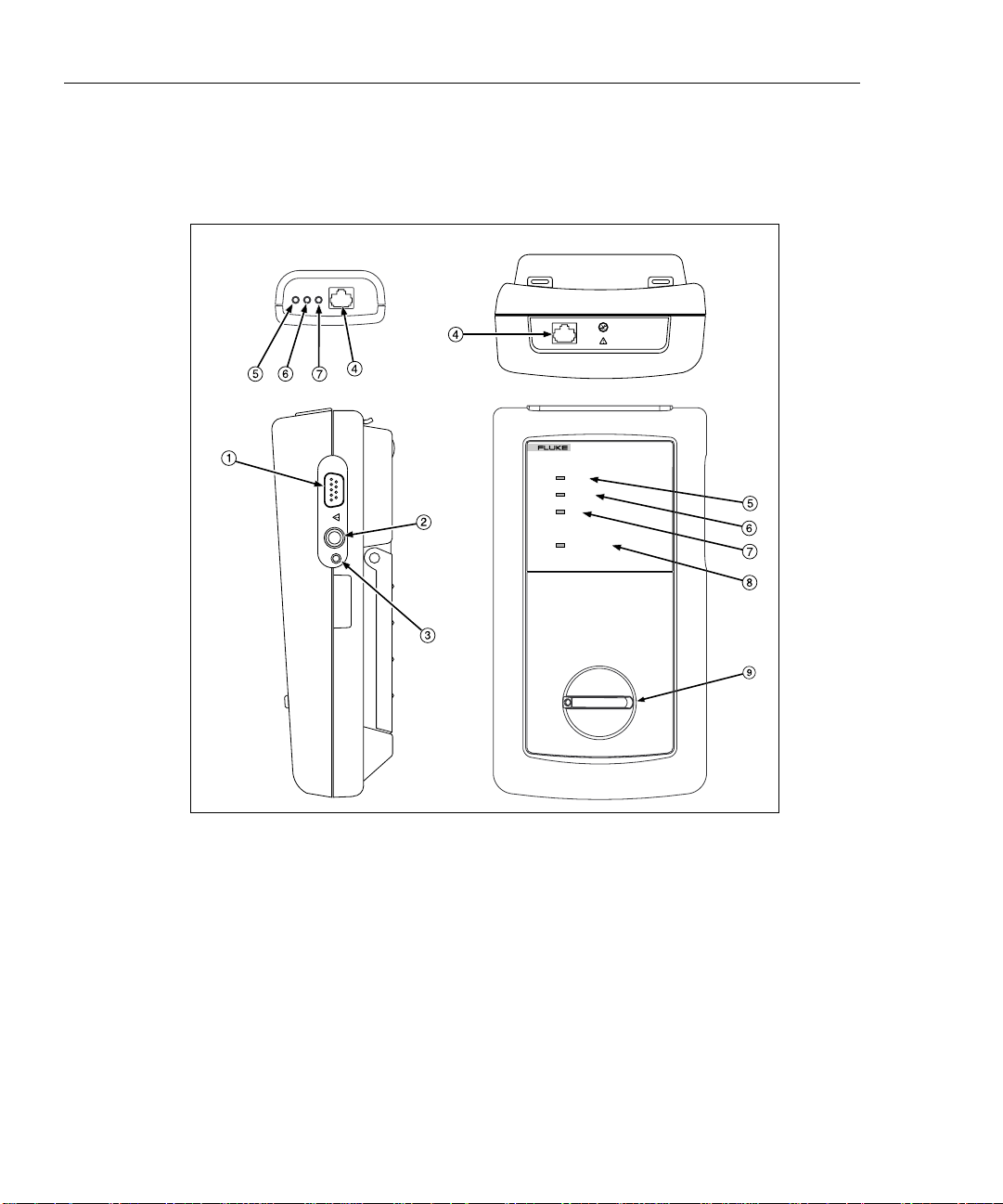
Remote Features
Figure 2-5 shows the features on the standard and smart remote units. Table 2-5
explains the functions of these items.
Standard Remote
PASS
TEST
FAIL
Smart Remote
SMART REMOTE
DSP-2000SR
PASS
TESTING
FAIL
LOW BATTERY
ON
OFF
2-14
gc06f.eps
Figure 2-5. Standard and Smart Remote Features
Page 31

Table 2-5. Remote Connectors and Features
Item Feature Description
Getting Started
Remote Features
2
1
2
3
4
5
6
7
RS-232C serial
port
AC adapter/
charger jack
AC power
indicator
RJ45 connector A shielded 8-pin jack for shielded and unshielded twisted pair cable.
Pass LED A green LED that turns on at the end of a test if no faults were
Test LED A yellow LED that turns on when a test is in progress.
Fail LED A red LED that turns on at the end of a test if one or more faults were
A DB9P connector for loading software updates.
Connection for the ac adapter/charger supplied with the test tool.
LED Style 1: A green LED that turns on when the test tool is powered
with the ac adapter/charger.
LED Style 2: A multicolor LED with four states:
Off: AC adapter/charger is not connected, or is connected without
the battery pack installed.
Blinking Red: The ac adapter/charger is trickle charging the battery
in preparation for fast charging. This mode indicates an extremely
low battery voltage. The test tool may not operate.
Steady Red: The ac adapter/charger is fast charging the battery.
Steady Green: Fast charging is complete. The ac adapter/charger
continues to trickle charge the battery.
detected.
detected.
8
9
Low-battery LED A LED that turns on when the smart remote battery voltage is low.
Rotary switch On/off switch for smart remote.
2-15
Page 32

DSP-100/2000
Users Manual
Strap and Bail
The test tool and the smart remote have a strap and a bail. Figure 2-6 shows how
to attach the strap and open the bail.
Figure 2-6. Attaching the Strap and Opening the Bail
Rotary Switch
The following paragraphs summarize the modes you can select with the rotary switch on
the main unit.
Off
Turns the test tool off. Setup information and test results that were saved via the
SAVE key are stored in nonvolatile memory.
2-16
gc07f.eps
Page 33

Autotest
Autotest is the most frequently used function in LAN cable testing. Autotest
performs all of the tests necessary to qualify the cable you are testing. When the
Autotest is complete, the tests that were run are listed with the overall result for
each test. You can also view detailed results for each test. Results from at least
500 Autotests can be saved for printing or transmission to a host computer.
The following tests apply to twisted pair cable:
• Wire Map: Tests for opens, shorts, crossed pairs, reversed wires, and split
• NEXT: Tests twisted pair cable for near-end crosstalk (NEXT).
• Length: Displays the length of twisted pairs in feet or meters.
• Propagation Delay: Measures the times taken for a signal to travel the length
• Delay Skew: Calculates the differences in propagation delays between the
• Impedance: Measures the impedance of each cable pair. If impedance
• Attenuation: Measures the attenuation of each cable pair.
• Resistance: Measures the loop resistance of each cable pair.
• ACR: Calculates the ratio of attenuation to crosstalk for all combinations of
• RL (Return Loss): Measures signal loss due to signal reflections in the cable.
• PSNEXT (Power Sum Next; Model DSP-2000 only): For each cable pair,
Getting Started
Rotary Switch
Note
The tests run during an Autotest on twisted pair cable depend on the
test standard selected. Tests not applicable to the selected test
standard are not run or displayed. For a list of tests applicable to
various test standards, see Table C-1 in Appendix C.
pairs.
of each cable pair.
cable pairs.
anomalies are detected, the test reports the largest anomaly detected on each
cable pair.
cable pairs.
PSNEXT is calculated as the sum of the NEXT from all other pairs.
2
2-17
Page 34

DSP-100/2000
Users Manual
Single Test
Monitor
The following tests apply to coaxial cable:
• Impedance: Measures the impedance of the cable.
• Resistance: Measures the loop resistance of the cable, shield, and terminator.
• Length: Measures the length of unterminated cables.
• Anomaly Detection: During a coaxial cable test, the test tool also detects and
reports the position of the largest impedance anomaly (if any are present) on
the cable.
The SINGLE TEST mode provides access to the individual tests defined by the
selected test standard, except for the ACR test. This mode also allows execution
of TDR and TDX analyzer tests. A scanning function, which continuously
repeats the test, is available for the wire map, resistance, TDR, and TDX analyzer
tests.
The MONITOR mode allows you to continuously monitor impulse noise on
network cables or network activity on Ethernet systems. Network activity is
monitored for collisions, jabber, and percentage of system utilization.
2-18
The MONITOR mode also includes a hub port locator, which helps you determine
port connections at a hub. Model DSP-2000 includes a hub port capabilities
feature that determines the standards supported by a port.
Page 35

Setup
Getting Started
Rotary Switch
Allows you to do the following:
• Select a test standard and cable type.
• Select an average cable temperature when temperature is required by the
selected test standard.
• Set the test tool to test cable installed in conduit when a conduit setting is
required by the selected test standard.
• Enable remote testing or automatic remote detection when you use a second
main unit or a smart remote as a remote unit.
• Set the cable identification number to increment automatically each time you
save Autotest results.
• Set the backlight timer to turn off the backlight after a specified period of
inactivity.
• Set the power-down timer to switch the test tool to a low-power mode after a
specified period of inactivity.
• Set the fault threshold for the impulse noise test.
• Select interface parameters for the serial port.
2
• Enable or disable the test tool’s beeper.
• Set the date and time.
• Select a format for the date and time.
• Select a unit for length measurements.
• Select a format for displaying decimal fractions.
• Select a language for the display and printed reports.
• Select a frequency for the power line noise filter.
• Enable or disable the shield continuity test.
• Modify test standards for custom cable configurations.
• Select 100 MHz or 155 MHz as the maximum frequency for NEXT, ACR, and
attenuation tests.
2-19
Page 36

DSP-100/2000
Users Manual
Allows you to send saved reports or report summaries to a serial printer. You can
print the results from previously stored Autotests. Also allows editing of the report
identification information.
Special Functions
Allows you to do the following:
• View or delete test reports saved in memory.
• Generate a tone to use with an inductive pickup to identify cable runs (Model
• Determine the cable NVP to ensure maximum accuracy of length and
• View the status of the NiCad battery in the main unit or smart remote.
• Calibrate the test tool to work with a new remote unit.
• Run a self-test to verify proper operation of the test tool and the remote.
DSP-2000 only).
resistance results.
Smart Remote (Model DSP-100)
The SMART REMOTE mode causes the test tool to function as a smart remote. In
the SMART REMOTE mode, when remote testing is enabled on the main unit, the
remote unit sends results from REMOTE tests to the main unit.
Turning On the Test Tool
To turn on the test tool, turn the rotary switch from OFF to any one of the
available modes. The power-up screen, which appears for about 3 seconds, shows
the software, hardware, and test standards versions for your main and remote
units.
During this time, the test tool also performs a self-test. If a fault is detected during
the self-test, the following message appears:
INTERNAL FAULT DETECTED. REFER TO MANUAL. For
information, see “If the Test Tool Fails” in Chapter 8.
2-20
Page 37

Selecting a Language for Displays and Reports
The test tool displays results and prints reports in English, German, French,
Spanish, and Italian.
To select a language for displays and reports, proceed as follows:
1. Turn the rotary switch to SETUP.
2. Press $Page Down four times.
3. Use D to highlight the currently selected language.
4. Press ! Choice.
5. Use D U to highlight the language you want.
6. Press E to accept the highlighted language. The test tool’s display now
appears in the selected language.
Performing a Self-Test
The self-test verifies that the test tool and the remote are operating properly. To
run the self-test, proceed as follows:
1. Turn the rotary switch to SPECIAL FUNCTIONS.
Getting Started
Turning On the Test Tool
2
2. Use D to highlight Self Test.
3. Press E.
4. Use the 2m Cat5 patch cable provided to connect the test tool to the remote as
described on the display.
5. Press T to start the self-test.
6. When the self-test is complete, you can either return to the main Special
Functions menu by pressing e or start a new operation by turning the
rotary switch to a new position.
If the self-test fails, refer to “If the Test Tool Fails” in Chapter 8.
2-21
Page 38

DSP-100/2000
Users Manual
Overvoltage Test
The test tool periodically checks for dc voltages on the cable connected to the
RJ45 jack. A dc voltage means that the test tool is connected to an active
telephone cable or other power source. If voltage is detected, the following
message appears:
WARNING! EXCESSIVE VOLTAGE DETECTED AT INPUT.
Voltage on the cable can damage the test tool or cause errors in measurements.
Voltage must be removed before you can run any tests.
Noise Test
The test tool periodically checks for excessive electrical noise on the cable under
test. If excessive noise is detected, the following message appears:
WARNING Excessive noise detected.
Measurement accuracy may be degraded. To continue the test,
press E. If you continue the test and then save the test results, the test
report will include the warning given above.
To stop the test and return to the first screen of the selected test mode, press e.
Configuring the Test Tool
Controlling the Backlight
To turn on the display backlight, press C on the keypad. Press the key again to
turn off the backlight. On Model DSP-2000, the backlight key toggles the
backlight between two levels of brightness.
You can set the backlight timer to automatically turn off the backlight after a
specified period of inactivity. You can also disable the backlight timer.
To set the backlight timer or disable the timer, proceed as follows:
1. Turn the rotary switch to SETUP.
2. Press $Page Down once.
3. Use D to highlight the backlight time-out setting.
4. Press ! Choice.
5. Use D U to highlight the desired time-out period or the disable status.
6. Press E to accept the highlighted selection.
2-22
Page 39

When the backlight time-out is enabled, the backlight timer starts counting down
after all tests are complete or after the last key entry or movement of the rotary
switch. To restart the backlight timer while the backlight is on, press any key
(except the backlight key) or turn the rotary switch to a new mode.
Adjusting the Display Contrast
To adjust the display contrast, hold down C for 1 second or longer. The
following message appears: USE D U KEYS TO ADJUST CONTRAST.
Adjust the contrast to the desired level then press E to accept the new
level. The display contrast setting is saved in memory when you turn off the test
tool.
Selecting a Power Line Filter Frequency
The test tool has a noise filter to keep ac noise (50 or 60 Hz) from affecting
resistance measurements.
To set the frequency of the noise filter to the frequency of your ac power, proceed
as follows:
1. Turn the rotary switch to SETUP.
Getting Started
Configuring the Test Tool
2
2. Press $Page Down four times.
3. Use D to highlight the power line frequency.
4. Press ! Choice.
5. Use D U to highlight the frequency you want.
6. Press E to accept the highlighted frequency.
2-23
Page 40

DSP-100/2000
Users Manual
Selecting a Test Standard and Cable Type
The test standard and cable type you select determine which standards are used
and which tests are run during cable testing. The test tool is equipped with
information for all the common test standards and cable types.
Several of the test standards for twisted pair cable are defined for both a channel
and a basic link configuration. The test limits for a channel are looser than those
for a basic link because the channel limits allow for the effects of two connections
at a horizontal cross-connect and a transition connector near the
telecommunications outlet in the work area. Figure 2-2 shows the connections
involved in a channel; Figure 3-1 shows the connections involved in a basic link.
To select a test standard and cable type, proceed as follows:
1. Turn the rotary switch to SETUP.
2. Press ! Choice.
3. Use D U to highlight the test standard you want.
4. Press E to accept the highlighted test standard. The test tool displays a
menu of the cable types that are valid for the selected test standard.
5. Use D U to select the cable type you want; then press E.
If you select a shielded cable type, you can enable or disable the shield continuity
test on page 6 of the SETUP screens.
You can test cables for NEXT, attenuation, and ACR up to 100 MHz or 155 MHz.
Because no industry standards specify cable performance beyond 100 MHz, there
are no test limits for these measurements.
The maximum frequency selection is on page 6 of the SETUP screens.
Selecting an Average Cable Temperature
Some test standards require you to select an average temperature for the cable you
are testing. The selected temperature appears on the display when you turn the
rotary switch to AUTOTEST. If the test standard has no temperature-dependent
limits, N/A is displayed.
If you select a test standard that has temperature-dependent limits, the test tool
uses a default value of below 21°C (69°F) for the average cable temperature.
2-24
Page 41

An increase in cable temperature causes an increase in attenuation. To compensate
for this increase, the test tool uses the temperature you select to modify the
attenuation test limits. To avoid passing faulty cables or failing good cables, select
the temperature that is closest to the cable’s average temperature.
To select an average cable temperature, proceed as follows:
1. Turn the rotary switch to SETUP.
2. Use D to highlight the average cable temperature.
3. Press ! Choice.
4. Use D U to highlight the temperature range you want.
5. Press E to select the highlighted temperature range.
Selecting a Conduit Setting
Some test standards require you to specify whether or not the cable is installed
inside conduit. If the test standard requires a conduit setting, the current setting
(yes or no) appears on the display when you turn the rotary switch to
AUTOTEST. If the test standard does not require a conduit setting, N/A is
displayed.
Getting Started
Configuring the Test Tool
2
Metal conduit slightly increases a cable’s attenuation. To compensate for this
increase, the test tool’s attenuation test limits are raised when the conduit setting
is set to “yes.”
To change the conduit setting, proceed as follows:
1. Turn the rotary switch to SETUP.
2. Use D to highlight the conduit setting.
3. Press ! Choice.
4. Use D U to highlight the setting you want.
5. Press E to accept the highlighted setting.
2-25
Page 42

DSP-100/2000
Users Manual
Selecting a Length Unit
The test tool displays length measurements in meters or feet.
To change the unit of measurement, proceed as follows:
1. Turn the rotary switch to SETUP.
2. Press $Page Down four times.
3. Press ! Choice.
4. Use D U to highlight the desired unit.
5. Press E to accept the highlighted unit.
Selecting a Numeric Format
The test tool displays decimal fractions with a decimal point separator (0.00) or a
comma separator (0,00).
To change the numeric format, proceed as follows:
1. Turn the rotary switch to SETUP.
2. Press $Page Down four times.
2-26
3. Use D to highlight the numeric format.
4. Press ! Choice.
5. Use D U to highlight the desired format.
6. Press E to accept the highlighted format.
Page 43

Setting the Date and Time
The test tool has a clock that records the date and time for saved test results.
To change the date or time or the format for the date or time, proceed as follows:
1. Turn the rotary switch to SETUP.
2. Press $Page Down three times.
3. Use D to highlight the date or time parameter you want to change.
4. Press ! Choice. The display you see next depends on which parameter
you are changing.
If you are changing the date or time, use $INC or #DEC to
increment or decrement the highlighted number. Use L R to move the
highlighted area from one number to another number.
If you are changing the date or time format, use D U to highlight the format
you want.
5. Press E to accept the highlighted date, time, or format.
Getting Started
Configuring the Test Tool
2
2-27
Page 44

DSP-100/2000
Users Manual
Setting the Power-Down Timer
To extend battery life, you can set the power-down timer to automatically switch
the test tool to a low-power mode after a selected period of inactivity. You can
also disable the power-down timer.
When the test tool switches to low-power mode, the display goes blank. To
reactivate the display, press C.
To set the power-down timer or enable/disable the timer, proceed as follows:
1. Turn the rotary switch to SETUP.
2. Press $Page Down once.
3. Use D to highlight the power-down timer status.
4. Press ! Choice.
5. Use D U to highlight the desired time-out period or the enable/disable
status.
6. Press E to accept your selection.
Model DSP-2000 turns itself off if not used for 30 minutes after power-down.
When this happens, pressing C turns on the test tool. The test tool then goes
through its power-on sequence as though it were turned on with the rotary switch.
Enabling or Disabling the Audible Tones
To enable or disable the test tool’s audible tones, proceed as follows:
1. Turn the rotary switch to SETUP.
2. Press $Page Down twice.
3. Use D to highlight the audible tone status.
4. Press ! Choice.
5. Use D U to highlight the desired enable or disable status.
6. Press E to accept your selection.
2-28
Page 45

Remote Lights, Messages, and Audible Tones
Remote Lights, Messages, and Audible Tones
The standard and smart remotes indicate various states by flashing light-emitting
diodes (LEDs) and emitting audible tones, as described in Table 2-6.
Table 2-6. Status Indications from Remotes
Status Standard Remote Indications Smart Remote Indications
Getting Started
2
Power on self-test passed. The unit beeps and all LEDs
flash in sequence.
Power on self-test failed. The unit beeps and the fail LED
flashes continuously.
Main unit is running a test. Test LED is on. Pass and fail
LEDs flash as tests pass or fail.
Previous test passed. Pass LED turns on for 15
seconds.
Previous test failed. Fail LED turns on for 15
seconds.
Battery voltage is low. Message appears on main unit. The unit beeps and the low-
Battery voltage is too low to
operate.
Overvoltage condition detected
on cable under test.
Message appears on main unit. The unit beeps and the low-
Message appears on main unit. The unit beeps and all LEDs
The unit beeps and all LEDs
flash in sequence.
The unit beeps and the fail LED
flashes continuously.
Testing LED is on. Pass and
fail LEDs flash as tests pass or
fail.
Pass LED turns on for 15
seconds.
Fail LED turns on for 15
seconds.
battery LED flashes
continuously.
battery LED is on continuously.
flash continuously.
2-29
Page 46

DSP-100/2000
Users Manual
Remote End Testing
If you have a second test tool or a smart remote, you can perform remote end
testing. The remote end testing feature allows you to run the near-end crosstalk
(NEXT) test at the far end of the cable and get the attenuation to crosstalk ratio
(ACR) from the far end of the cable without switching the positions of the main
and remote units.
When you enable remote testing the NEXT@REMOTE and ACR@REMOTE
tests appear in the AUTOTEST and SINGLE TEST modes if the selected test
standard requires the tests. Model DSP-2000 also includes RL@REMOTE and
PSNEXT@REMOTE tests.
Selecting Auto Detect allows the test tool to identify the remote as a standard or
smart remote and run the REMOTE tests as appropriate.
To enable remote end testing, proceed as follows:
1. Turn the rotary switch on the main unit to SETUP.
2. Use D to highlight the remote end testing status.
3. Press ! Choice.
4. Use U to highlight Enable or Auto Detect; then press E
2-30
If you use a DSP-100 unit as a remote, the remote unit displays the following
status messages:
SMART REMOTE READY: The remote unit is waiting for the main unit to
start a test.
SMART REMOTE TESTING: The main unit is running a test.
SMART REMOTE PASS or FAIL: Pass or fail is the overall result of the test
just completed. This message is displayed for about 3 seconds after a test is
completed.
SMART REMOTE READY
PREVIOUS TEST: PASS or PREVIOUS TEST: FAIL: The remote is
waiting for the main unit to start another test. Pass or fail is the overall result of
the previous test.
Page 47
Remote Communication Error
If you are running the NEXT@REMOTE or RL@REMOTE test, and the main
unit detects a communication problem with the remote, the following message
appears on the main unit: REMOTE communication error. This
message means that the REMOTE data cannot be transmitted to the main unit,
usually because the cable is defective. To verify proper remote operation, run a
self-test as described in the earlier section “Performing a Self-Test.”
Battery Status
The test tool displays a message when its battery voltage or the remote battery
voltage is low. Table 2-7 shows the battery status messages and what you should
do if a battery message appears.
Note
To ensure continued operation while charging the battery, always
connect the ac adapter/charger when the message
WARNING RECHARGEABLE BATTERY VOLTAGE IS
LOW appears.
Getting Started
Remote Communication Error
2
Table 2-7. Battery Status Messages
Message Displayed What You Should Do
WARNING RECHARGEABLE BATTERY VO
LTAGE IS LOW.
RECHARGEABLE BATTERY VOLTAGE IS
TOO LOW TO OPERATE.
WARNING REMOTE BATTERY VOLTAGE
IS LOW.
WARNING REMOTE BATTERY VOLTAGE
IS TOO LOW TO OPERATE.
INTERNAL DATA STORAGE BATTERY VO
LTAGE IS LOW.
Connect the ac adapter/charger.
Turn the test tool off and connect the ac
adapter/charger. If the tool does not operate
when you turn it on, turn it off again and allow
the battery to charge for about 30 minutes.
For a standard remote, have a 9V alkaline
battery available. For a smart remote or second
main unit, connect the ac adapter/charger.
Replace the alkaline battery in standard remote.
Charge the NiCad battery in a second main unit
or smart remote.
Have the lithium battery replaced at a Fluke
Service Center.
2-31
Page 48

DSP-100/2000
Users Manual
Battery Status Display
To see the charge level of the main unit’s NiCad battery, turn the rotary switch to
SPECIAL FUNCTIONS; then select Battery Status. To see the charge
level of the smart remote’s battery, connect the smart remote to the main unit (use
the CABLE TEST jack on Model DSP-2000); then use ! to toggle the display.
Connecting the battery charger can change the readings displayed
on the battery status screen. These changes are due to the charger’s
effect on the test tool’s charging circuit.
Note
2-32
Page 49

Chapter 3 provides the following information:
• Instructions and test result descriptions for an Autotest on twisted pair cable.
• Instructions and test result descriptions for an Autotest on coaxial cable.
• Instructions for saving Autotest results.
Autotest Softkeys
The following softkey functions are active on the Autotest screens noted. The
PSNEXT screen is available on Model DSP-2000 only.
! or @ View Result: ! shows the results of the last Autotest run.
Active on the first Autotest screen. @ shows detailed test results regarding the
highlighted cable pair or pairs. Active on the first screens for the NEXT,
attenuation, ACR, RL, and PSNEXT tests.
Chapter 3
Autotest
@ View Plot: Press to see a frequency response plot of the test results.
Active on the first screen and the results screen for the NEXT, attenuation, ACR,
RL, and PSNEXT tests.
@ Next Pair, @ Next Pairs: Press to see the detailed results or
the plot for the next cable pair or pairs tested. Active on the results and plot
screens for the NEXT, attenuation, ACR, and RL tests.
! 155 MHz: Press to see NEXT, ACR, or attenuation results plotted up to
155 MHz. This key is available only if the frequency option under SETUP is set to
155 MHz.
3-1
Page 50

DSP-100/2000
Users Manual
Autotest on Twisted Pair Cable
The procedures for an Autotest on shielded and unshielded twisted pair cable are
the same. When shielded cable is selected, the test tool performs an additional test
for shield continuity if the shield test is enabled in SETUP.
To run the Autotest on twisted pair cable, refer to Figure 3-1 and proceed as
follows:
RJ45
Jack
CABLE ANALYZER
DSP-2000
2 Meters
Wall Outlet
2 Meters
34
2
1
TEST
FAULT
INFO
EXIT
AUTO
TEST
OFF
SAVE
ENTER
WAKE UP
MONITOR
SINGLE
SETUP
TEST
PRINT
SPECIAL
FUNCTIONS
SMART
REMOTE
Test Tool
Patch Panel
Smart
Remote
ON
OFF
Figure 3-1. Autotest Connections for Twisted Pair Cable (Basic Link Configuration and DSP-
2000 Shown)
3-2
DSP-2000SR
PASS
TESTING
FAIL
LOW BATTERY
SMART REMOTE
gc08f.eps
Page 51

Autotest
Autotest on Twisted Pair Cable
Note
The REMOTE tests will run only if the remote is a smart remote or a
DSP-100 with the SMART REMOTE mode selected.
1. If you are using a DSP-100 main unit as the remote, turn the remote unit’s
rotary switch to SMART REMOTE. If you are using a smart remote unit, turn
its rotary switch to ON.
2. Use a 2m patch cable of the correct impedance to connect the remote to the far
end of the cable link.
3. On Model DSP-100, remove any cable connected to the test tool’s BNC
connector.
4. Turn the rotary switch on the main unit to AUTOTEST.
5. Verify that the settings displayed are correct. You can change these settings in
the SETUP mode.
6. Use a 2m patch cable of the correct impedance to connect the test tool to the
near end of the cable link. On Model DSP-2000, connect to the CABLE TEST
jack.
7. Press T to start the Autotest.
3
Notes
Pressing T when the previous Autotest was not saved causes the
test tool to display a warning message. In this case, you can either
save the results of the previous test by pressing S or delete the
results and start a new Autotest by pressing T.
If a remote is not connected, the test tool displays the message
SCANNING FOR REMOTE and does not run the Autotest until a
remote is connected.
If the calibration message appears, refer to “Calibrating the Test
Tool” in Chapter 6 for complete calibration instructions.
3-3
Page 52

DSP-100/2000
Users Manual
Link Performance Grade Result (Headroom)
When an Autotest is complete, the display shows the overall result (pass or fail)
and the worst-case NEXT margin, or headroom. Headroom is the smallest
difference found between the measured NEXT value and the limit. This number
serves as a figure of merit that reflects the overall performance of the link.
Automatic Diagnostics (Model DSP-2000)
If an Autotest fails, you can press the FAULT INFO key to see more specific
information on the cause of the failure. Figure 3-2 shows examples of automatic
diagnostics displays for a NEXT failure and an open pin failure.
The arrow in the diagram at the top of the display shows the location of the
failure. The bottom half of the display describes the failure and suggests ways to
fix the fault. When appropriate, softkeys let you see the plot or plots relevant to
the failure. If more than one fault was found, you can use the
$Next Fault and #Prev Fault softkeys to scroll through the
diagnostics displays.
3-4
Page 53

Automatic Diagnostics (Model DSP-2000)
Figure 3-2. Examples of Automatic Diagnostics Displays
Autotest
3
gc09c.eps
3-5
Page 54

DSP-100/2000
Users Manual
Autotest Results for Twisted Pair Cable
To see detailed results from a test, use D U to highlight the test on the main
Autotest menu; then press E.
Note
The tests run during an Autotest on twisted pair cable depend on the
test standard selected. Tests not applicable to the selected test
standard are not run or displayed. For a list of tests applicable to
various test standards, see Table C-1 in Appendix C.
Wire Map Test
The wire map test tests and displays the wire connections between the near and far
ends of the cable on all four pairs. Shield continuity is also tested if a shielded
cable type is selected and you have not disabled shield testing in SETUP. The
pairs tested are those defined by the selected test standard. Table 3-1 shows
examples of wire map displays.
If the wire map test passes, the Autotest continues. You can view the wire map
test results when the Autotest is complete. If the wire map test fails, the Autotest
halts and the wire map screen appears with the word FAIL. You can then save
the wire map results by pressing
$Continue Test.
S. To continue the Autotest, press
Correct wiring
(Top row
represents nearend connector.)
3-6
Wire Map
Condition
Table 3-1. Wire Map Displays
Display Schematic
(only affected pairs
shown)
1
2
3
6
4
5
7
gc42i.eps
8
gc43i.eps
Description
1
Cable wiring is
2
correct. Shield (S)
3
shown only if
6
required by
4
selected test
5
7
standard.
8
Page 55

Autotest Results for Twisted Pair Cable
Table 3-1. Wire Map Displays (continued)
Autotest
3
Wire Map
Condition
Crossed wires
Reversed pairs
Crossed pairs
Short
Display Schematic
(only affected pairs
shown)
1
2
3
6
gc44i.eps
1
2
gc46i.eps
1
2
3
6
gc48i.eps
1
2
3
6
gc45i.eps
gc47i.eps
gc49i.eps
Description
1
A wire in the 1,2
2
pair is crossed with
3
a wire in the 3,6
6
pair. Wiring does
not form a
recognizable
circuit.
Wires 1 and 2 are
crossed.
1
2
Pairs 1,2 and 3,6
1
are crossed.
2
3
6
Wires 1 and 3 are
1
shorted. You can
2
use the TDR test
3
to locate the short.
6
Open
Split pair
gc50i.eps
gc52i.eps
gc54i.eps
gc51i.eps
Wire 1 is open.
1
2
You can use the
1
2
TDR test to locate
the open.
gc53i.eps
1
2
3
6
A wire in the 1,2
1
pair is twisted with
2
a wire in the 3,6
3
pair. You can use
6
the TDX analyzer
to locate the split
pair.
gc55i.eps
3-7
Page 56

DSP-100/2000
Users Manual
Resistance
The resistance test measures the dc loop resistance for each cable pair. The
resistance results screen displays the resistance, limit, and pass/fail result for each
cable pair. A PASS result means that the measured resistance is less than the
limit. A FAIL result means that the measured resistance exceeds the limit.
Length
The length test measures the length of each cable pair tested. The main Autotest
results screen shows the length of the cable pair having the shortest electrical
delay. Length is displayed in meters or feet. The length results screen displays the
length, limit, and pass/fail result for each cable pair. You can change the length
units in the SETUP mode, as described in “Selecting a Length Unit” in Chapter 2.
A 2 to 5 percent difference in measured length between twisted pairs
is typical. This difference is due to differences in the number of
twists in the cable pairs.
Differences between measured and actual values of cable length can
be caused by variations in the cable’s NVP value. To ensure
maximum accuracy of length measurements, perform an NVP
calibration as described in Chapter 6.
Notes
3-8
The length test limits include an extra 10% to account for variations
in NVP.
A PASS result means that the measured length is within the specified limit for the
selected test standard. A FAIL result means that the measured length exceeds the
limit.
Page 57

Propagation Delay and Delay Skew
Propagation delays are the times taken in nanoseconds for a test pulse to travel the
length of each cable pair.
Delay skews are the differences in propagation delays between the shortest delay,
which is displayed as 0 ns, and the delays of the other cable pairs.
The propagation delay and delay skew results show a limit if the test is required
by the selected test standard. If the test is not required, the results always show
PASS.
Characteristic Impedance
The characteristic impedance test determines the approximate characteristic
impedance of each cable pair.
Note
Impedance measurements require a cable at least 5m (16 ft) long.
Cables shorter than this length will always pass the impedance test.
A PASS result means that the measured impedance is within the specified limit
for the selected test standard. A FAIL result means that the measured impedance
exceeds the specified limit, or an impedance anomaly is detected.
Autotest
Autotest Results for Twisted Pair Cable
3
A Warning result means that the measured impedance exceeds test limits, but
the characteristic impedance test is not required by the selected test standard. The
warning result causes a warning to appear as the test summary result in printed
reports.
If an impedance anomaly is detected on a cable pair, the display shows the
distance to the anomaly (in meters or feet) and the result is displayed as FAIL.
The test tool reports an anomaly if 15% or more of the test signal is reflected. If
more than one anomaly is detected on a cable pair, the distance to the largest
anomaly is displayed. You can use the TDR test to plot the locations and sizes of
impedance anomalies on the cable.
3-9
Page 58

DSP-100/2000
Users Manual
Attenuation
Incorrect conduit or temperature settings can cause false
attenuation results. You can change these settings in the SETUP
mode, as described in “Configuring the Test Tool” in Chapter 2.
The attenuation test measures the loss of signal strength over the length of the
cable.
The first attenuation results screen shows the cable pairs tested, the worst-case
attenuation margin found, and a PASS or FAIL result for each pair.
To see detailed results for the cable pairs, use D U to highlight a cable pair, then
press @ View Result. Table 3-2 describes the items on the attenuation
results screen.
Item Description
Note
Table 3-2. Items on the Attenuation Results Screen
Pair
Result
Attenuation If the test passed, this value is the highest measured attenuation. If the test
Frequency
Limit
Margin
The cable pair relevant to the results.
The overall result for the test. A PASS result means that measured
attenuation is lower than the specified limit for the selected test standard. A
FAIL result means that the measured attenuation is higher than the
specified limit.
failed, this value is the highest measured attenuation that exceeds the test
limits.
If the test passed, this frequency is where the highest measured attenuation
occurred. If the test failed, this is where the highest failing value of
attenuation occurred.
The highest attenuation value acceptable at the frequency shown. This value
is based on the maximum allowable cable length.
The difference between the worst-case attenuation and the limit. A positive
number means that the measured attenuation value is lower than the limit. A
negative number means that the attenuation is higher than the limit.
3-10
Page 59

Autotest
Autotest Results for Twisted Pair Cable
Pressing @ View Plot produces the attenuation plot screen. Figure 3-3
shows an example of the screen and Table 3-3 describes the items on the screen.
1
6
2
5
4
3
gc10c.eps
Figure 3-3. The Attenuation Plot Screen
Table 3-3. Items on the Attenuation Plot Screen
3
Item Description
The cable pair relevant to the plot.
1
Frequency range in MHz of the attenuation test.
2
Margin is the difference between the limit and measured values plotted at the cursor’s
3
position. Use L R to move the cursor left or right. If you move the cursor beyond the highest
test frequency specified by the selected test standard, the readout shows the attenuation
value at the cursor’s position.
The measured attenuation for the cable pair.
4
The attenuation limits, as defined by the selected test standard. A crosshair is shown if the
5
limit is defined for only one frequency.
Decibels of attenuation.
6
3-11
Page 60

DSP-100/2000
Users Manual
NEXT Test
The NEXT test measures the crosstalk between cable pairs. This crosstalk value is
expressed as the difference in amplitude (in dB) between the test signal and the
crosstalk signal. NEXT is measured from the main-unit end of the cable over a
frequency range defined by the selected test standard.
If the NEXT test fails, you can use the TDX analyzer to locate the source of the
crosstalk on the cable.
The first NEXT screen displays the cable pairs tested, the worst-case NEXT
margin, and the test result for each set of pairs.
To see detailed results for the cable pairs, use D U to highlight the pairs; then
press @ View Result. Table 3-4 describes the items on the NEXT results
screen.
Table 3-4. Items on the NEXT Results Screen
Item Description
Pairs
Result
NEXT
Frequency
Limit
Margin
The cable pairs relevant to the results.
The overall result for the NEXT test. A PASS result indicates that the NEXT
between the cable pairs was higher than the specified NEXT for the selected test
standard. A FAIL result indicates that the NEXT was lower than specifications.
The worst-case NEXT. Worst-case NEXT is the measured NEXT value that is
closest to falling below specifications. If the NEXT falls below specifications, the
value displayed is the value that falls the farthest below specifications.
The frequency where the worst-case NEXT value is measured.
The lowest NEXT value acceptable for the worst-case frequency.
The difference between the worst-case NEXT value and the limit. A positive number
means that the measured NEXT value is higher than the limit (PASS). A negative
number means that the NEXT is lower than the limit (FAIL).
3-12
Page 61

Autotest
Autotest Results for Twisted Pair Cable
Pressing @ View Plot produces the NEXT plot screen. Figure 3-4 shows
an example of the screen and Table 3-5 describes the items on the screen.
1
6
3
5
4
3
Figure 3-4. The NEXT Plot Screen
Table 3-5. Items on the NEXT Plot Screen
Item Description
The cable pairs relevant to the plot.
1
Frequency range in MHz of the NEXT test.
2
Margin is the difference between the limit and measured values plotted at the cursor’s
3
position. Use L R to move the cursor left or right. If you move the cursor beyond the highest
test frequency specified by the selected test standard, the readout shows the NEXT value at
the cursor’s position.
The limits for NEXT, as defined by the selected test standard. A crosshair is shown if the
4
limit is defined for only one frequency.
2
gc11c.eps
Decibels of crosstalk attenuation (NEXT) between the cable pairs.
5
The measured NEXT for the cable pairs.
6
3-13
Page 62

DSP-100/2000
Users Manual
NEXT@REMOTE Results
The NEXT@REMOTE test and its results are identical to the NEXT test
described above, except that the NEXT@REMOTE measurements are taken from
the remote end of the cable and sent to the main unit.
ACR
The ACR test calculates the ratio of attenuation to crosstalk (ACR) for each
combination of cable pairs. ACR is expressed as the difference (in dB) between
the measured NEXT and attenuation values. ACR is calculated using values
obtained from the NEXT and attenuation tests.
ACR Results
The first ACR results screen shows the NEXT pairs and attenuation pair used to
calculate the ACR result, the worst-case ACR margin, and a PASS or FAIL
result for each set of pairs.
To see detailed results for the cable pairs, use D U to highlight the pairs; then
press @ View Result. Table 3-6 describes the items on the ACR results
screen.
3-14
Page 63

Autotest Results for Twisted Pair Cable
Table 3-6. Items on the ACR Results Screen
Item Description
Autotest
3
NEXT Pairs
Atten. Pair
Result
ACR (dB)
Frequency
Limit
Margin
The pairs that produced the crosstalk value used in calculating the ACR result.
The pair that produced the attenuation value used in calculating the ACR result.
The overall result for the ACR test. A PASS result means that the calculated ACR
is higher than the value specified for the selected test standard. A FAIL result
means that the calculated ACR is lower than the specified value.
The worst-case ACR. Worst-case ACR is the calculated ACR value that is closest
to exceeding specifications. If the ACR exceeded specifications, the value
displayed is the ACR value that exceeded specifications by the greatest amount.
The frequency where the worst-case ACR value is calculated.
The specified limit for the ACR at the worst-case frequency. The limit is defined by
the test standard selected.
The difference between the worst-case ACR and the limit. A positive number
means that the worst-case ACR is higher than the limit. A negative number means
that the worst-case ACR is lower than the limit.
3-15
Page 64

DSP-100/2000
Users Manual
Pressing @ View Plot produces the ACR plot screen. Figure 3-5 shows an
example of the screen and Table 3-7 describes the items on the screen.
6
5
4
3
Figure 3-5. The ACR Plot Screen
Table 3-7. Items on the ACR Plot Screen
Item Description
1
2
gc12c.eps
3-16
The cable pairs relevant to the plot.
1
Frequency range in MHz of the ACR test.
2
Margin is the difference between the limit and measured values plotted at the cursor’s
3
position. Use L R to move the cursor left or right. If you move the cursor beyond the highest
test frequency specified by the selected test standard, the readout shows the ACR value at
the cursor’s position.
The ACR limits, as defined by the selected test standard.
4
Decibels of ACR for the cable pair.
5
The measured ACR for the cable pairs.
6
Page 65

ACR@REMOTE
The ACR@REMOTE test is identical to the ACR test, except that the ACR values
are calculated using NEXT@REMOTE values.
Return Loss (RL)
The RL test measures the difference between a test signal’s amplitude and the
amplitude of signal reflections returned by the cable. The results of the RL test
indicate how well the cable’s characteristic impedance matches its rated
impedance over a range of frequencies.
The first RL results screen shows the cable pairs tested, the worst-case RL margin,
and a PASS or FAIL result for each pair. To see detailed results for the cable
pairs, use D U to highlight a pair; then press @ View Result. Table 3-8
describes the items on the RL results screen.
Table 3-8. Items on the RL Results Screen
Item Description
Autotest
Autotest Results for Twisted Pair Cable
3
Pair
Result
RL
Frequency
Limit
Margin
The cable pair relevant to the results.
The overall result for the RL test. A PASS result means that the measured RL is
lower than the specified limit for the selected test standard. A FAIL result means
that the measured RL is higher than specified limit.
The worst-case return loss. Worst-case RL is the measured RL value that is closest
to exceeding specifications. If the RL exceeds specifications, the value displayed is
the value that exceeds specifications by the greatest amount.
The frequency where the worst-case RL occurred.
The specified limit for RL at the worst-case frequency. The limit is defined by the
test standard selected.
The difference between the worst-case RL and the Limit. A positive number means
that the worst-case RL is better than the limit. A negative number means that the
worst-case RL exceeds the limit.
3-17
Page 66

DSP-100/2000
Users Manual
Pressing @ View Plot produces the RL plot screen. Figure 3-6 shows an
example of the screen and Table 3-9 describes the items on the screen.
1
6
5
4
3
Figure 3-6. The RL Plot Screen
Table 3-9. Items on the RL Plot Screen
Item Description
The cable pair relevant to the plot.
1
Frequency range in MHz of the RL test.
2
Margin is the difference between the limit and measured values plotted at the cursor’s
3
position. Use L R to move the cursor left or right. If you move the cursor beyond the highest
test frequency specified by the selected test standard, the readout shows the RL value at
the cursor’s position.
The limits for RL, as defined by the selected test standard.
4
2
gc13c.eps
Decibels of RL for the cable pair.
5
The measured RL for the cable pair.
6
RL@REMOTE (Model DSP-2000)
The RL@REMOTE test is identical to the RL test, except that the RL values are
measured from the remote end of the cable.
3-18
Page 67

PSNEXT (Power Sum NEXT; Model DSP-2000)
The PSNEXT results show how much each cable pair is affected by the combined
NEXT from the other pairs. PSNEXT is expressed as the difference in amplitude
(in dB) between the crosstalk received on a cable pair and a test signal transmitted
on the other pairs.
PSNEXT is calculated from NEXT values. The descriptions of the results are the
same as for NEXT results, except that they show the sum effect of NEXT on a
cable pair.
Autotest on Coaxial Cable
To run an Autotest on coaxial cable, refer to Figure 3-7 and proceed as follows:
Autotest
Autotest on Coaxial Cable
3
3-19
Page 68

DSP-100/2000
Users Manual
PC
PC
12345678
PC
12345678
12345678
For Length Test,
remove far-end
Terminator
BNC “T”
Connector
3-20
CABLE ANALYZER
DSP-2000
34
2
1
Test Tool
TEST
FAULT
INFO
EXIT
AUTO
TEST
OFF
SAVE
ENTER
MONITOR
SINGLE
SETUP
TEST
PRINT
SPECIAL
FUNCTIONS
SMART
REMOTE
Figure 3-7. Autotest Connections for Coaxial Cable (Model DSP-2000 Shown)
gc04f.eps
Page 69

1. Turn off any PC nodes connected to the cable you are testing.
2. If you want the Autotest to report cable length, remove the terminator from the
far end of the cable.
3. Turn the rotary switch to AUTOTEST.
4. Verify that the test standard and cable type displayed are correct. You can
change these settings in the SETUP mode.
5. On Model DSP-100, remove any cable connected to the test tool’s RJ45
connector.
6. Remove the terminator from the near end of the coaxial cable and connect the
cable to the BNC connector on the test tool. On Model DSP-2000, use the
RJ45 to coaxial adapter to connect the cable to the CABLE TEST jack.
7. Press T to start the Autotest.
Autotest Results for Coaxial Cable
An Autotest on coaxial cable performs the following tests:
Characteristic Impedance
Autotest
Autotest Results for Coaxial Cable
3
Note
Impedance measurements require a cable at least 5m (16 ft) long.
Terminated cables shorter than this length will always pass the
impedance test. Unterminated cables shorter than this length will
always fail the impedance test.
The characteristic impedance test determines the approximate characteristic
impedance for the cable. A PASS result means that the impedance is within the
limit specified by the selected test standard. A FAIL result means that the
impedance exceeds the limit. You can use the TDR test to plot the locations and
sizes of all impedance anomalies on the cable.
3-21
Page 70

DSP-100/2000
Users Manual
Resistance
The resistance test measures the loop resistance of the cable and the terminator. If
a terminator is not connected or if the cable is open, the resistance value is
reported as OPEN. If the cable or the terminator is shorted, the resistance value is
reported as near 0Ω. Resistance values over 400Ω are reported as OPEN.
Length
Because a cable terminator eliminates signal reflections in coaxial
cable, the test tool cannot measure the length of a terminated
coaxial cable.
The length test measures the length of the cable when a terminator is not
connected. If a terminator is connected, the result of the length test is reported as
NO REFLECTION.
A PASS result means that the measured length is within the limit specified by the
selected test standard. A FAIL result means that the measured length exceeds the
limit.
Note
Anomaly
This result is shown at the bottom of the screen only if an impedance anomaly is
detected. The test tool reports an anomaly if 10% or more of the test signal is
reflected. The result shows the distance to the largest anomaly detected.
Notes
Differences between measured and actual values of cable length can
be caused by variations in the cable’s NVP value. To ensure
maximum accuracy of length measurements, perform an NVP
calibration as described in Chapter 6.
The length test limits include an extra 10% to account for variations
in NVP.
3-22
Page 71

Saving Autotest Results
The test tool’s memory can store the results of 500 or more Autotests, depending
on the software version and test standard used. You can save the results from an
Autotest anytime after the Autotest is complete, but before another Autotest or a
Single Test is started.
To save Autotest results, proceed as follows:
1. After an Autotest is complete, press S. The test save screen appears, as
shown in Figure 3-8. Table 3-10 describes the items on the screen.
2. Use the appropriate editing keys to enter a cable identification name for the
test results you are saving.
To delete the character left of the cursor, press $Delete. To add
characters to the name, use the L R and D U keys to highlight characters in
the list, then enter the highlighted character in the cable identification by
pressing E. To edit characters in the middle of a name, use ! to
move the cursor into the name.
Model DSP-2000 allows you to increment or decrement an alphanumeric
character anywhere in the cable identification. Use ! to highlight the
desired character; then press @ INC or #DEC. To move the cursor
back to the right-most character, press ! until the cursor wraps back to
the right.
Autotest
Saving Autotest Results
3
3. Press S to store the test results with the cable identification displayed. A
confirmation screen appears for about 2 seconds.
3-23
Page 72

DSP-100/2000
Users Manual
1
2
3
4
Figure 3-8. Screen for Saving Autotest Results
Table 3-10. Items on the Autotest Save Screen
Item Description
The characters you can use to make a name for the test results you are saving.
1
The date and time when the Autotest was saved.
2
The default name assigned to the results from the most recently completed test.
3
Softkey for moving the cursor to edit characters in the middle of the cable
4
identification. On Model DSP-100 with software versions 3.0 and earlier, use the
@ ³ softkey to move the cursor back to the right. On Model DSP-2000, press
! Â until the cursor wraps back to the right.
The remaining number of locations available for storing Autotest results.
5
5
gc15c.eps
3-24
Page 73

The Autotest Report
Automatically Incrementing the Cable Identification Name
The test tool’s auto increment function increments the last alphanumeric character
of the cable identification name each time you save Autotest results.
To enable or disable the auto increment function, proceed as follows:
1. Turn the rotary switch to SETUP.
2. Press $ Page Down once.
3. Press ! Choice.
4. Use D U to highlight the status you want.
5. Press E to select the highlighted status.
If Memory is Full
If the Autotest results you save fill the last available memory location, the
following message appears:
WARNING! TEST RESULT MEMORY IS NOW FULL. If you try to
save additional test results after the memory has been filled, the following
message appears:
UNABLE TO SAVE TEST RESULTS. MEMORY IS FULL.
Autotest
3
To save additional test results, you must first delete one or more test reports from
memory. You can delete test reports in the SPECIAL FUNCTIONS mode. For
complete instructions, see Chapter 5, “Viewing and Printing Saved Reports.”
You can see how many memory spaces are available by pressing the
$Memory softkey, which appears on several Autotest displays.
The test tool can store the results from more than 500 Autotests. The
exact number of memory spaces available depends on the number of
tests run by the selected test standard.
The Autotest Report
Figures 3-9, 3-10, and 3-11 on the following pages show how Autotest results
appear in printed reports. You can print Autotest reports or edit the report’s
identification information in the PRINT mode. See Chapter 5, “Viewing and
Printing Saved Reports,” for complete instructions.
Note
3-25
Page 74

DSP-100/2000
Users Manual
The result printed on a report summary can be a pass or fail, or warning. A failure
of any test required by the selected test standard produces a fail result on the
report summary. A warning appears on reports for twisted pair cable if a length,
impedance, propagation delay, or delay skew test produced a warning. The table
in Appendix C shows which test standards can produce a warning result for these
tests.
Mukilteo Cable Co. Test Summary: FAIL
SITE: Westshore Business Park Cable ID: Bldg7Rm9Cbl3
OPERATOR: Kim Nguyen Date / Time: 01/07/97 10:01:05am
NVP: 69.0% FAULT ANOMALY THRESHOLD: 15% Test Standard: TIA Cat 5 Channel
FLUKE DSP-2000 S/N: 6680915 Cable Type: UTP 100 Ohm Cat 5
HEADROOM: -20.4 Software Version: 3.29
Standards Version: 3.06
Wire Map FAIL Result RJ45 PIN: 1 2 3 4 5 6 7 8 S
Split pairs detected: 1,2-3,6 | | | | | | | |
Patch Cable BAD or Patch Cable too short RJ45 PIN: 1 2 3 4 5 6 7 8
Pair 1,2 3,6 4,5 7,8
Impedance (ohms), Limit 80-120 107 105 W 106 108
Anomaly (ft) 71
Length (ft), Limit 328 75 77 74 74
Prop. Delay (ns) 110 113 109 109
Delay Skew (ns), Limit 50 1 4 0 0
3-26
Resistance (ohms) 4.6 4.9 4.9 4.6
Attenuation (dB) 5.1 6.7 5.2 4.9
Limit (dB) 24.0 22.5 24.0 24.0
Margin (dB) 18.9 15.8 18.8 19.1
Frequency (MHz) 100.0 88.3 100.0 100.0
Pairs 1,2-3,6 1,2-4,5 1,2-7,8 3,6-4,5 3,6-7,8 4,5-7,8
NEXT (dB) 36.6 F 43.5*F 40.2 26.1 F 31.8 F 50.1*F
Limit (dB) 49.2 44.6 34.9 46.5 45.6 50.8
Margin (dB) -12.6 -1.1 5.3 -20.4 -13.8 -.7
Frequency (MHz) 4.9 9.3 35.4 7.1 8.1 3.9
* Measurement is within the accuracy limits of the instrument.
gc16f.eps
Figure 3-9. Part of an Autotest Report for Twisted Pair
Page 75

Autotest
The Autotest Report
Mukilteo Cable Co. Test Summary: PASS
SITE: World Technology Ctr. Cable ID: Rm16COAX34
OPERATOR: Mike Marshall Date / Time: 01/07/97 10:50:12am
NVP: 80.0% FAULT ANOMALY THRESHOLD: 10% Test Standard: Coax Cables
FLUKE DSP-2000 S/N: 6680915 Cable Type: 10Base2 (50 Ohms)
Software Version: 3.29
Standards Version: 3.06
Impedance (ohms), Limit 42-58 49
Length (ft), Limit 607 No Reflection
Prop. Delay (ns) No Reflection
Resistance (ohms), Limit 48.0-65.0 50.5
gc17f.eps
Figure 3-10. Autotest Report for Coaxial Cable
MUKILTEO CABLE CO.
Cable ID: Date / Time: SITE: Length(ft):
RM1CBL1 01/06/97 09:51:46am MOUNTAIN REAL ESTATE 77 PASS
RM1CBL2 01/06/97 09:56:53am MOUNTAIN REAL ESTATE 98 FAIL
RM2CBL1 01/06/97 10:00:44am MOUNTAIN REAL ESTATE 77 PASS
RM2CBL2 01/06/97 10:01:50am MOUNTAIN REAL ESTATE 120 PASS
RM2CBL3 01/06/97 10:04:16am MOUNTAIN REAL ESTATE 99 PASS
3
Total Length: 471
Figure 3-11. Autotest Report Summary
gc18f.eps
3-27
Page 76

DSP-100/2000
Users Manual
3-28
Page 77

Running Individual Tests
Chapter 4 provides the following information:
• Descriptions of the test results produced by the TDX analyzer and TDR
test.
• Instructions for running Single Tests on twisted pair cable.
• Instructions for running Single Tests on coaxial cable.
• Instructions for using the tests available in the MONITOR mode.
• Instructions for using the tone generator (Model DSP-2000).
Single Tests for Twisted Pair Cable
The SINGLE TEST mode on the rotary switch allows individual execution of the
tests available in the Autotest mode, except the ACR test. SINGLE TEST mode
features two additional tests: the TDX analyzer and the TDR test.
Chapter 4
4-1
Page 78

DSP-100/2000
Users Manual
Scanning Function
The Single Test versions of the wire map, resistance, TDR, and TDX analyzer
tests include a scanning function, which you can activate by pressing the
#Scanning ON softkey. The scanning function runs the test repeatedly
and updates the display each time a test is complete. This function is useful for
finding intermittent problems on a cable.
To extend battery life, connect the ac adapter/charger when using
the scanning function for more than 1 minute.
When to Use a Remote Unit
A remote unit is required only when testing twisted pair cable. Table 4-1 shows
which cable tests require a remote and which remotes support each test.
If a remote unit is detected at the start of a Single Test, the test tool runs a wire
map test before running the selected test. If the wire map test fails, the test tool
stops the test and displays the wire map. Press $Continue Test to run
the selected test.
Note
4-2
Note
Model DSP-2000 is compatible only with Model DSP-2000SR units.
Model DSP-100 is not compatible with Model DSP-2000SR units.
Page 79

Running Individual Tests
When to Use a Remote Unit
Table 4-1. Remote Requirements for Cable Tests
Test Remote Unit
Autotest Required. Supported by all remotes.
Wire Map Required. Supported by all remotes.
NEXT Required. Supported by all remotes.
NEXT@REMOTE Required. Supported by smart remotes and DSP-100 main units used as
remotes. With a standard remote, results can be obtained by switching the
positions of the remote and main unit and retesting.
Length Optional. Supported by all remotes. Without a remote, the limit and pass/fail
result are not shown.
Impedance Optional. Supported by all remotes.
Attenuation Required. Supported by all remotes.
Resistance Optional. Supported by all remotes. Without a remote, the resistance of
cable pairs is reported as “open,” assuming the cable pair is not shorted.
RL Required. Supported by all remotes.
RL@REMOTE Required. Supported by DSP-2000 smart remote.
4
ACR Required. Supported by all remotes. Test available only in Autotest mode.
ACR@REMOTE Required. Supported by smart remotes and DSP-100 main units used as
remotes. With a standard remote, results can be obtained by switching the
positions of the remote and main unit and retesting. Test is available only in
Autotest mode.
PSNEXT
PSNEXT@REMOTE
TDR Optional. Supported by all remotes. Without a remote, the end of the cable
TDX Analyzer Recommended. Supported by all remotes. Without a remote, results from
Impulse Noise Recommended. Supported by all remotes. Without a remote, test results
Traffic Monitor Never used.
Required. Supported by DSP-2000 smart remote. Test is available only in
Autotest mode.
is not identified.
tests on short cables may be unreliable.
may not represent the level of noise present on a terminated cable.
4-3
Page 80

DSP-100/2000
Users Manual
Running a Single Test on Twisted Pair Cable
To run a test as a Single Test, refer to Figure 4-1 and proceed as follows:
RJ45
Jack
CABLE ANALYZER
DSP-2000
2 Meters
34
2
1
TEST
FAULT
INFO
EXIT
AUTO
TEST
OFF
SAVE
ENTER
WAKE UP
MONITOR
SINGLE
SETUP
TEST
PRINT
SPECIAL
FUNCTIONS
SMART
REMOTE
Test Tool
Patch Panel
Wall Outlet
2 Meters
SMART REMOTE
DSP-2000SR
PASS
TESTING
FAIL
LOW BATTERY
4-4
Smart
Remote
ON
OFF
Figure 4-1. Single Test Connections for Twisted Pair Cable (Model DSP-2000 Shown)
Note
For instructions on running the TDR test or TDX analyzer, or
running tests from the MONITOR mode, see the later sections on
those topics in this chapter.
Note
The standard remote does not support remote end testing.
gc19f.eps
Page 81

Running Individual Tests
When to Use a Remote Unit
1. If you are using a DSP-100 main unit as the remote, turn the remote unit’s
rotary switch to SMART REMOTE. If you are using a smart remote unit, turn
its rotary switch to ON.
2. Use a 2m patch cable of the correct impedance to connect the remote to the far
end of the cable link.
3. On Model DSP-100, remove any cable connected to the test tool’s BNC
connector.
4. Turn the rotary switch on the main unit to SINGLE TEST.
5. Use a 2m patch cable of the correct impedance to connect the test tool to the
near end of the cable link. On Model DSP-2000, connect to the CABLE TEST
jack.
6. Use U D to highlight the test you want to run.
7. Press E to start the highlighted test.
Note
If a remote is required for the test, but is not connected, the test tool
displays the message SCANNING FOR REMOTE and does not
run the test until a remote is connected.
4
If the calibration message appears, refer to “Calibrating the Test
Tool” in Chapter 6 for complete calibration instructions.
4-5
Page 82

DSP-100/2000
Users Manual
The TDX Analyzer
The TDX (Time Domain Crosstalk) analyzer displays the locations where
crosstalk is occurring on the cable. You can view the test results in a list or plot
format. The list format shows the largest crosstalk value detected on the cable.
The plot shows all of the crosstalk detected.
The crosstalk values displayed are adjusted to compensate for cable attenuation.
The values represent the approximate levels of crosstalk as they appear at the
sources of the crosstalk. A level over 50 represents a crosstalk magnitude that
exceeds the limit specified by the selected test standard.
The TDX analyzer results are not intended for use in determining if a cable meets
specifications; the results are intended to help you locate the sources of crosstalk
on a cable. To determine if a cable meets specifications for crosstalk, run the
NEXT test.
Running the TDX Analyzer
You can run the TDX analyzer with or without a remote. If you run
the analyzer without a remote, the results may be unreliable.
Note
4-6
To run the TDX analyzer, proceed as follows:
1. Turn off any PCs connected to the link you are testing.
2. If you are using a DSP-100 main unit as a remote, turn the remote unit’s
rotary switch to SMART REMOTE. If you are using a smart remote unit, turn
its rotary switch to ON.
3. If you are testing with a remote, connect the remote to the far end of the cable
link.
4. Turn the rotary switch on the main unit to SINGLE TEST.
5. Verify that the test standard and cable type displayed are correct.
6. On Model DSP-100, remove any cable connected to the test tool’s BNC
connector.
7. Connect the test tool to the near end of the cable link. On Model DSP-2000,
connect to the CABLE TEST jack.
8. Use D to highlight TDX Analyzer.
9. Press E to run the TDX analyzer.
Page 83

If the test tool does not detect a remote, the following message appears:
NO REMOTE DETECTED. To run the TDX analyzer, press E. To
restart the analyzer and scan for the remote again, press T. To return to the first
Single Test screen, press e.
TDX Analyzer Results
When the TDX analyzer test is complete, the TDX analyzer results screen
appears. Table 4-2 describes the items on the analyzer screen.
Table 4-2. Items on the TDX Analyzer Results Screen
Item Description
Running Individual Tests
The TDX Analyzer
4
Pairs
Peak
Distance
#
View Plot
The cable pairs relevant to the results.
The highest magnitude of crosstalk measured on the cable pair. A peak over
50 indicates a crosstalk level that exceeds the limit specified by the selected
test standard. Crosstalk levels are adjusted to compensate for cable
attenuation.
The measured distance from the main unit to the peak crosstalk value.
Press to see a plot that shows where crosstalk is detected on the cable.
4-7
Page 84

DSP-100/2000
Users Manual
TDX Analyzer Plot
To view a TDX analyzer plot for a set of cable pairs, use D U to highlight the
pairs, then press #View Plot to see the plot screen for the pairs. Figure
4-2 shows an example of a TDX analyzer plot and Table 4-3 describes the items
on the screen.
Figure 4-2. Example of a TDX Analyzer Plot for a Good Twisted Pair Cable Run
1
2
3
4
5
gc20c.eps
4-8
Table 4-3. Items on a TDX Analyzer Plot
Item Description
1 The cable pairs relevant to the results.
2 The distance along the cable under test. The 0 at the left of the scale represents the
location of the main test tool.
3 Magnitude of crosstalk on the cable pair. A peak over 50 indicates a crosstalk level
that exceeds the limit specified by the selected test standard. Crosstalk levels are
adjusted to compensate for cable attenuation.
4 The Cursor Readout shows the distance to the crosstalk source at the cursor’s
position. Use L R to move the cursor left or right.
5 Use D U to change the maximum distance of the horizontal scale.
Page 85

The TDR Test
The TDR (Time Domain Reflectometry) test helps you locate impedance
anomalies on a cable by reporting the locations of signal reflections caused by the
anomalies.
The test locates anomalies caused by problems such as shorts, opens, poor
connections, and mismatches in cable types. You can view the location and size of
the anomalies in a list or plot format.
The reflection values displayed are adjusted to compensate for cable attenuation.
The values represent the approximate size of the reflections as they appear at the
anomalies.
How to Terminate the Cable
You can run the TDR test on twisted pair cable with or without a remote unit, and
on coaxial cable with or without a terminator. Table 4-4 describes how
termination devices affect the results reported for twisted pair and coaxial cable.
Table 4-4. Effects of Termination on TDR Results
Running Individual Tests
The TDR Test
4
Cable Type and
Termination
Twisted pair
with no
termination
Twisted pair
with remote
Coaxial cable
with no
terminator
Coaxial Cable
with terminator
Listed Results Show the Following: Plotted Results Show the Following:
Displays the message
No Remote Detected. Results
show the two largest reflections
greater than or equal to 15%. The
largest reflection probably comes from
the end of the cable, but is not
identified as the end.
Two largest reflections greater than or
equal to 15%. Largest reflection is
identified as the end of the cable.
Two largest reflections greater than or
equal to 10%. The largest reflection
comes from the end of the cable, but is
not identified as the end.
No Reflection reported for a
good cable. On a faulty cable, the test
reports the two largest reflections, but
does not identify end of cable.
All reflections are shown.
All reflections are shown.
All reflections are shown. The largest
reflection comes from the end of the
cable.
All reflections are shown. The plot will
not show a reflection from the
terminated end.
4-9
Page 86

DSP-100/2000
Users Manual
Running the TDR Test on Twisted Pair Cable
To run the TDR test on twisted pair cable, proceed as follows:
1. Disconnect any PCs from the link you are testing.
2. If you are using a DSP-100 main unit as a remote, turn the remote unit’s
rotary switch to SMART REMOTE. If you are using a smart remote unit, turn
its rotary switch to ON.
3. If you are testing with a remote, connect the remote to the far end of the cable
link.
4. Turn the rotary switch on the main unit to SINGLE TEST.
5. Verify that the test standard and cable type displayed are correct.
6. On Model DSP-100, remove any cable connected to the test tool’s BNC
connector.
7. Connect the test tool to the near end of the cable link. On Model DSP-2000,
connect to the CABLE TEST jack.
8. Use D to highlight TDR.
9. Press E to run the TDR test.
Running the TDR Test on Coaxial Cable
To run the TDR test on coaxial cable, proceed as follows:
1. Turn off any PC nodes connected to the cable you are testing.
2. If desired, remove the terminator from the far end of the cable.
3. Turn the rotary switch to SINGLE TEST.
4. Verify that the test standard and cable type displayed are correct.
5. Remove any cable connected to the test tool’s unused RJ45 connector.
6. Remove the terminator from the near end of the coaxial cable and connect the
cable to the BNC connector on the test tool. On Model DSP-2000, use the
RJ45 to BNC adapter to connect the cable to the CABLE TEST jack.
7. Use D to highlight TDR.
8. Press E to run the TDR test.
4-10
Page 87

Running Individual Tests
The TDR Test
TDR Results Screen
When the TDR test is complete, the TDR results screen appears. Table 4-5
describes the items on the screen.
Table 4-5. Items on a TDR Results Screen (Twisted Pair Results)
Item Description
Pair The cable pair relevant to the results. Not shown for coaxial cable results.
Distance The first distance is the measured distance from the test tool to the end of the
cable. The second distance, if shown, is the distance from the test tool to the
beginning of the largest anomaly that caused a reflection greater than the
limit defined by the selected test standard.
Peak The percentage of the test signal reflected at the peak of the anomaly.
# View Plot Press to see a plot of the locations and reflection percentages of the
impedance anomalies detected.
Note
It is possible for impedance anomalies to be detected when testing
from one end of the cable, but not from the other end. This
discrepancy is caused by attenuation of the signal reflections
returning from the anomaly.
4
TDR Plot Screen
To view the TDR plot for a cable pair, use D U to highlight one of the pairs;
then press #View Plot to see the plot screen for that pair. Figure 4-3
shows an example of a TDR plot and Table 4-6 describes the items on the plot.
4-11
Page 88

DSP-100/2000
Users Manual
5
6
7
Figure 4-3. Example of a TDR Plot (Twisted Pair Results)
Table 4-6. Items on a TDR Plot (Twisted Pair Results)
Item Description
1 The cable pair relevant to the results.
2 The peak value as reported on the results screen.
1
2
4
3
gc21c.eps
3 The distance along the cable under test. The 0 at the left of the scale represents the location
of the main test tool.
4 The distance to the end of the cable as reported on the results screen.
5 The percentage of reflected signal relative to the size of the TDR test signal. Positive values
indicate locations on the cable where the impedance is higher than the cable’s characteristic
impedance. Negative values indicate locations on the cable where the impedance is lower
than the cable’s characteristic impedance.
6 The Cursor Readout shows the location and the reflection percentage at the cursor’s
position. Use L R to move the cursor left or right.
7 Use D U to change the maximum distance of the horizontal scale.
Single Test Results for Twisted Pair Cable
The Single Test results for twisted pair cable are identical to those displayed by an
Autotest, with exceptions noted in the following paragraphs.
Tests not required by the selected test standard produce a Warning result when
measured values exceed the test’s limits.
4-12
Page 89

Wire Map
Wire map results are identical to the Autotest version. See “Wire Map” in Chapter
3 for details. The Single Test version of the wire map test includes the scanning
function.
Length
If a remote is connected, the length test and results are identical to the Autotest
version. See “Length” in Chapter 3 for details.
If a remote is not connected, the test tool displays the message
NO REMOTE DETECTED, and the limit and result columns are not shown. If
the length of a cable pair cannot be determined, the length value on the display is
blank and WARNING appears in the result column.
NEXT and NEXT@REMOTE
The NEXT test and results are identical to the Autotest version. See “NEXT” in
Chapter 3 for details.
The NEXT@REMOTE test is available only when using a second main DSP-100
unit or a smart remote as a remote unit. Remote end testing must be enabled on the
main unit. The NEXT@REMOTE test and results are identical to the Autotest
version. See “NEXT@REMOTE” in Chapter 3 for details.
Running Individual Tests
Single Test Results for Twisted Pair Cable
4
Impedance
The impedance test and results are identical to the Autotest version. See
“Impedance” in Chapter 3 for details.
Attenuation
The attenuation test and results are identical to the Autotest version. See
“Attenuation” in Chapter 3 for details.
Resistance
If a remote is connected, the results displayed are identical to the display in
Autotest. See “Resistance” in Chapter 3 for details.
If a remote is not connected, the test tool displays the message
NO REMOTE DETECTED and all pair resistances are reported as OPEN. A
cable pair with a resistance greater than 400Ω is also reported as OPEN.
4-13
Page 90

DSP-100/2000
Users Manual
Return Loss (RL) and RL@REMOTE
The RL test is identical to the Autotest version. See “Return Loss” in Chapter 3
for details.
The RL@REMOTE test is available only when using a DSP-2000 with a DSP2000 smart remote. Remote end testing must be enabled on the main unit. See
"RL@REMOTE" in Chapter 3 for details.
Single Tests for Coaxial Cable
The Single Test mode on the rotary switch allows individual execution of the
coaxial cable tests available in the Autotest mode. The TDR test is also available
as a Single Test for coaxial cable.
The coaxial cable tests available as Single Tests produce results displayed in the
same format as displayed in the Autotest mode.
Running a Single Test on Coaxial Cable
For instructions on running the TDR test, see the earlier section
“The TDR Test.” For instructions on running tests in the MONITOR
mode, see the later section “Monitoring Network Activity.”
Note
4-14
To run a Single Test on coaxial cable, refer to Figure 4-4 and proceed as follows:
1. Turn off any PC nodes connected to the cable you are testing.
2. If you want to measure cable length, remove the terminator from the far end of
the cable you are testing.
3. Turn the rotary switch to SINGLE TEST.
4. Verify that the test standard and cable type are correct. You can change these
settings in the SETUP mode.
5. Remove any cable connected to the test tool’s unused RJ45 connector.
6. Remove the terminator from the near end of the coaxial cable and connect this
end of the cable to the BNC connector on the test tool. On Model DSP-2000,
use the RJ45 to BNC adapter to connect the cable to the CABLE TEST jack.
7. Use U D to highlight the test you want to run.
8. Press E to start the highlighted test.
Page 91

PC
Running Individual Tests
Single Tests for Coaxial Cable
4
PC
12345678
PC
12345678
12345678
For Length Test,
remove far-end
Terminator
BNC “T”
Connector
CABLE ANALYZER
DSP-2000
34
2
1
Test Tool
TEST
FAULT
INFO
EXIT
AUTO
TEST
OFF
SAVE
ENTER
MONITOR
SINGLE
SETUP
TEST
PRINT
SPECIAL
FUNCTIONS
SMART
REMOTE
Figure 4-4. Single Test Connections for Coaxial Cable (Model DSP-2000 Shown)
gc22f.eps
4-15
Page 92

DSP-100/2000
Users Manual
Single Test Results for Coaxial Cable
The Single Test results for coaxial cable are identical to those displayed by an
Autotest, with exceptions noted as follows.
Impedance
Identical to Autotest version. See “Impedance” in Chapter 3 for details.
Resistance
Identical to Autotest version. See “Resistance” in Chapter 3 for details. The Single
Test version of the resistance test includes the scanning function.
Length
Identical to Autotest version. See “Length” in Chapter 3 for details.
TDR for Coaxial Cable
The TDR test is described for both twisted pair and coaxial cable in the earlier
section “The TDR Test.”
Monitoring Network Activity
The MONITOR mode on the rotary switch allows you to monitor Ethernet traffic
for collisions, jabber, peak traffic and percentage of network utilization. You can
monitor traffic on 10BaseT twisted pair or 10Base2 coaxial cable. Model DSP2000 can monitor traffic on 10/100BaseTX cable as well.
This feature allows you to identify active cables and provides some information
on network activity. If you want to troubleshoot active networks, contact your
Fluke representative for information on LAN diagnostic tools.
When connected to a network, the test tool automatically generates link pulses to
activate the hub. Model DSP-2000 uses Auto-Negotiation when attempting to link
to monitor 10/100BaseTX traffic. If a link state with the hub does not occur, the
test tool displays the warning message NO LINK PULSE.
To monitor network traffic on a twisted pair or coaxial Ethernet network, refer to
Figure 4-5 and proceed as follows:
4-16
Page 93

Running Individual Tests
Monitoring Network Activity
WCaution
When using a coaxial T-connector to connect the test tool
to a network, never allow the T-connector to touch a
conductive surface. Such contact could disrupt net work
operation by creating a ground loop.
Note
To extend battery life, use the ac adapter/charger when monitoring
network traffic for extended periods. While monitoring network
traffic, the test tool’s automatic power-down function is disabled.
4
Test Tool
12345678
RJ45
Jacks
12345678
BNC
Connection
PC
Shown
Test Tool
CABLE ANALYZER
DSP-2000
34
2
1
TEST
SAVE
FAULT
INFO
ENTER
EXIT
MONITOR
SINGLE
SETUP
TEST
AUTO
PRINT
TEST
SPECIAL
OFF
FUNCTIONS
SMART
REMOTE
PC
Figure 4-5. Connections for Monitoring Network Traffic (Model DSP-2000 Shown)
gc23f.eps
4-17
Page 94

DSP-100/2000
Users Manual
1. Turn the rotary switch to MONITOR.
2. Use D to highlight either 10BaseT Traffic on RJ45
(10/100BaseTX Traffic on RJ45 on Model DSP-2000) or
10Base2 Traffic on BNC.
3. Remove any cable connected to the test tool’s unused test connector.
4. Use a patch cable of the correct impedance to connect the test tool to the
network as shown in Figure 4-5. On Model DSP-2000, connect to the jack
indicated by the arrow at the top of the display. Use the RJ45 to BNC adapter
if necessary.
5. Press T to start the traffic test.
6. When using Model DSP-2000, use the #10T Only or
#100TX Only softkey to select traffic monitoring at 10 Mb/s or 100
Mb/s.
If you don't know which speed to use, and the test tool is not already trying to
link using Auto-Negotiation, press #until the display reads
Auto-Negotiation. This causes the test tool to select the proper speed
to match the hub.
As the traffic test runs, the results shown on the test tool’s display are updated
every second. Table 4-7 describes the items on the screen.
4-18
Page 95

Table 4-7. Items on the Traffic Monitor Screen
Item Description
Running Individual Tests
Monitoring Network Activity
4
Utilization
Last 1
second
Utilization
Average
Utilization
Peak
Collisions
Last 1
second
Collisions
Average
Collisions
Peak
Bottom of screen
! Sound
On
@ Sound
Off
Percentage of the network’s transmission bandwidth used over the last 1
second. Utilization includes correct frames, collisions, and jabber. The
percentage indicates the current traffic density.
The average of all the 1-second utilization percentages since the start of the
test.
The highest 1-second utilization percentage recorded since the start of the test.
The percentage of collision frames as compared to the total number of frames
detected in the last 1 second. Collisions are counted when runt packets are
detected.
The average of all the 1-second collision percentages since the start of the test.
The highest 1-second collision percentage recorded since the start of the test.
If jabber is detected, the message Jabber Detected appears in this space.
A jabber is reported if a frame is detected to be larger than the maximum legal
size. If no link pulse is detected, the message NO LINK PULSE appears in
this space.
Activates and deactivates a sound that represents network activity.
$Stop
Test
Stops the traffic test and freezes the screen. To restart the traffic test, press
T.
4-19
Page 96

DSP-100/2000
Users Manual
Identifying Hub Port Connections
The hub port locator helps you determine which port a cable is connected to at a
hub. The locator sends a link pulse to the hub, causing the port’s LED to blink.
To identify a hub port connection, proceed as follows:
1. On Model DSP-100, remove any cable connected to the test tool’s BNC
connector.
2. Use a patch cable of the correct impedance to connect the test tool to the
network connection. On Model DSP-2000, connect to the MONITOR jack.
3. Turn the rotary switch to MONITOR.
4. Use D to highlight the hub port locator selection; then press E.
5. Locate the connected port by finding the flashing LED on the hub’s LED
panel.
Monitoring Impulse Noise
The Monitor Impulse Noise function allows you to monitor electrical noise on
inactive twisted pair cable. Pair 3, 6 is monitored.
The noise test takes noise voltage samples every second. Voltages that exceed the
impulse noise threshold are regarded as noise “hits.” If the 10BaseT standard is
selected, the noise test results include a pass or fail indication. A fail result is
displayed if more than two noise hits are detected in a 10-second interval.
Changing the Impulse Noise Threshold
You can set the impulse noise threshold to a value from 100 to 500 mV in
increments of 10 mV. The default noise threshold value is 270 mV.
To change the noise threshold, proceed as follows:
1. Turn the rotary switch to SETUP.
2. Press $ Page Down once.
3. Use D to highlight the impulse noise threshold setting.
4. Press ! Choice.
5. Use # DEC or $INC to change the threshold.
6. Press E to store the threshold setting.
4-20
Page 97

Running the Impulse Noise Test
The connector type for the noise test is always RJ45. The noise test is not valid for
coaxial cable because the level of noise on coaxial cable is negligible.
To monitor impulse noise, refer to Figure 4-6 and proceed as follows:
RJ45
Jack
CABLE ANALYZER
DSP-2000
2 Meters
34
2
1
TEST
FAULT
INFO
EXIT
AUTO
TEST
OFF
SAVE
ENTER
WAKE UP
MONITOR
SINGLE
SETUP
TEST
PRINT
SPECIAL
FUNCTIONS
SMART
REMOTE
Test Tool
Patch Panel
Running Individual Tests
Monitoring Impulse Noise
Wall Outlet
2 Meters
SMART REMOTE
DSP-2000SR
PASS
TESTING
FAIL
LOW BATTERY
4
Smart
Remote
ON
OFF
Figure 4-6. Connections for Monitoring Impulse Noise (Model DSP-2000 Shown)
gc24f.eps
4-21
Page 98

DSP-100/2000
Users Manual
Note
To extend battery life, use the ac adapter/charger when monitoring
impulse noise for extended periods. While monitoring impulse noise,
the test tool’s automatic power-down function is disabled.
Note
Monitoring impulse noise without a remote connected may produce
unreliable test results.
1. If you are using another main unit as the remote, turn the remote unit’s rotary
switch to SMART REMOTE. If you are using a smart remote unit, turn its
rotary switch to ON.
2. Use a 2m patch cable of the correct impedance to connect the remote to the far
end of the cable link.
3. On Model DSP-100, remove any cable connected to the test tool’s BNC
connector.
4. Turn the rotary switch to MONITOR.
5. Use D to highlight Impulse Noise on RJ45.
6. Use a 2m patch cable of the correct impedance to connect the test tool to the
near end of the cable link. On Model DSP-2000, connect to the CABLE TEST
jack.
4-22
7. Press T to start the noise test.
Page 99

Noise Test Results
As the noise test runs, the displayed test results are updated every second after the
first 10-second sample period. Table 4-8 describes the items on the screen.
Item Description
Running Individual Tests
Determining Hub Port Capabilities (Model DSP-2000)
Table 4-8. Items on the Noise Monitor Screen
4
Impulse Noise
Threshold
Noise Test The overall result of the noise test. Displayed only when 10BaseT is
Average The average number of noise hits per second since the start of the test.
Peak The highest number of noise hits per second and the time at which the peak
$Stop Test Stops the noise test and freezes the screen. To restart the noise test, press
The minimum level of noise that is considered to be a noise hit. The default
threshold is 270 mV. If you want to change the fault threshold, see the earlier
section “Changing the Impulse Noise Threshold.”
selected. A PASS result means that no 10-second intervals included more
than two noise hits. A FAIL result means that more than two noise hits were
detected during a 10-second interval.
was recorded.
T.
Determining Hub Port Capabilities (Model DSP-2000)
This test determines if a hub supports the following standards:
• Auto-Negotiation
• 10BaseT
• 100BaseTX
• 100BaseT4
• 100BaseTX Full Duplex
• 10BaseT Full Duplex
To determine hub port capabilities, proceed as follows:
1. Use a patch cable of the correct impedance to connect the network connection
to the test tool’s MONITOR jack.
2. Turn the rotary switch to MONITOR.
3. Use D to highlight HUB Port Capabilities; then press E.
4-23
Page 100

DSP-100/2000
Users Manual
Using the Tone Generator (Model DSP-2000)
If you have an inductive pickup device, you can use the test tool’s tone generator
to identify cable runs and connections. The tone generator produces a signal on
the cable under test. You can hear the signal as an audible tone when you place an
inductive pickup device near the cable or one of the cable’s connectors.
To use the tone generator, proceed as follows:
1. Turn the rotary switch to SPECIAL FUNCTIONS.
2. Use a patch cable of the correct impedance to connect the test tool to the
CABLE TEST jack.
3. Use D to highlight Tone Generator; then press E.
4. Use an inductive pickup device along the cable run or at far end connectors to
determine which cable is connected to the test tool.
4-24
 Loading...