

Page 1

Specifications
Standard Specifications
General Specifications
● External Dimensions; Weight (with I/O module installed)
DR231:
approximately 438 (W)3291 (H)3336 (D) mm; approximately 13 kg
DR232:
approximately 438 (W)3291 (H)3301 (D) mm; approximately 9 kg
DS400:
approximately 336 (W)3165 (H)3100 (D) mm; approximately 2.5 kg
DS600:
approximately 422 (W)3176 (H)3100 (D) mm; approximately 3.5 kg
For model DR231, the DC power supply option adds 45 mm to the depth and 1.5
kg(f) to the weight.
● AC Power Supply
Rated supply voltage: 100 to 240 VAC
Usable supply voltage: 90 to 250 VAC
Rated supply frequency: 50/60 Hz
● DC Power Supply (/P6 option, only for the DR231 stand-alone model)
Rated supply voltage: 12 to 28 VDC
Usable supply voltage: 10 to 32 VDC
Terminal: Dedicated connector
Note: When both AC and DC power are connected to a DC
DC Power Supply Voltage
20 to 28 V
28 to 32 V
● Insulation Resistance
At least 20 MΩ at 500 VDC between the power supply and ground, between each
terminal and the ground, and between input terminals
● Withstanding Voltage
Between power supply terminal and ground: 1,500 VAC (50/60 Hz, 1 min.)
Between input/output terminal and ground: 1,500 VAC (50/60 Hz, 1 min.)
● Normal Operating Conditions
Supply frequency: 50 Hz ±2% or 60 Hz ±2%
Ambient temperature:
Ambient humidity: 20 to 80% RH (between -10 and 40˚C)
● Safety Standards
CSA C22.2 No. 1010.1-92, IEC1010-1:1995, EN61010
● EMI Standard
EN55011:1991 Group 1 class A
● EMC Standard
EN50082-2:1995
System Configuration
● Configuration Method
DR231: Configure a system with this model by specifying
DR232: Configure a system with this model by combining one or
Connecting Modules and Subunits (DR232)
● Standard Modules and Software for System Configuration
The following modules and software can be installed in a main unit and subunit to
configure a data acquisition system.
Input Modules: Universal (DCV, TC, RTD and DI), DCV/TC/DI
Communications Modules
Alarm Contact Output Modules:
DI/DO Modules: Two alarm output contacts (NO-C-NC) and fail output
Extension Modules: Interfaces for remote power supply
Software: DAQ 32(standard software)
● Types and Number of Modules That Can Be Connected
DR231: Specify the types of modules and the number
DR232: Communications module, DI/DO module or alarm
DS400/600 Input module, alarm contact output modules, DI/DO
● Connection of Subunits
DR231: Cannot be connected.
DR232: Up to 6 subunits can be connected. One subunit can
Input Section
● Number of Input Channels
DR231: 10 to 30 channels (Specify the number of channels
DR232: 0 channel. Expandable up to 300 channels by
● Types of Input Modules
DR231: Universal (DC voltage, thermocouple, RTD and
DR232: Universal (DC voltage, thermocouple, RTD and
● Measurement Range: See the specifications for each input module.
power supply model, which of the power supplies is
used depends on the voltage of the DC power supply
connected as follows.
<20 V
DR231, DR232 0 to 50˚C (FD operation 5 to 40˚C)
DS400, DS600 Panel mount –10 to 60˚C
necessary options, such as the input and
communications functions, according to the model
code when ordering.
more of the modules and subunits listed below.
dedicated, power monitor, strain, pulse, direct current
(mA) and digital input
Connectable to DS400 and DS600
: Ethernet, GP-IB, RS-232C and RS-422A/485
Connectable to DR232 main unit
4 contacts (C contact: NO-C-NC) and 10 contacts (A
contact: NO-C)
Connectable to DR232 Main unit or DS400 and DS600
Connectable to DR232 Main unit or DS400 and DS600
Up to 1 module/1 system can be connected.
One extension module can be connected to each
DS400 and DS600.
(should be used with extension base units)
DAQ 32 Plus (optional software)
according to the model code.
contact output module
module and extension modules
Four or six modules can be connected.
be installed on the rear panel by screws.
when ordering.)
Power monitor input option: 2 or 6 channels
connecting subunits.
contact), DCV/TC/DI dedicated (specify the types
when ordering), power monitor option
contact), DCV/TC/DI dedicated, power monitor,
strain, pulse, direct current (mA) and digital input
module
Power Supply Used
AC power supply
Indeterminate
DC power supply
Desk-top –10 to 50˚C
● Measurement Interval: 0.5, 1, 2, 3, 4, 5, 6, 10, 12, 15, 20, 30 and 60 seconds
DR231: Maximum of 2 s per 30 channels
DR232:
The measurement interval is dependent on the slowest input module if input
modules of different measurement intervals are connected at the same time.
● A/D Integration Period
Manual selection or automatic switchover between 20 ms (50 Hz), 16.7 ms (60
Hz) and 100 ms (10 Hz)
Minimum measurement interval when the 100-ms integration mode becomes:
DR231: 30 channels: 6 seconds
DR232: 4 seconds per 300 channels (including the subunit)
Recording section (DR231/232 main unit)
● Recording Method
Raster scan method, 10-color wire dot recording
● Number of Recording Points
300 points maximum (stand-alone model: 30 points + AC 6 points)
● Recording Paper
Effective recording width
● Analog recording color (You can specify a color for each channel.)
Purple, red, green, blue, brown, black, navy blue, yellow-green, red-purple,
orange
● Analog Recording Interval
FIX: Recording takes place at the specified measurement
AUTO: Linked to recording paper feed speed
● Recording Paper Feed
Paper feed speed: 1 to 1,500 mm/hour
Display Section
● Display Section
Display: VFD display (5 x 7 dot matrix, 3 lines)
Number of characters: 22 characters (large/1 line), 40 characters (2 lines)
Memory Function Section
● Memory Media
3.5-inch floppy disk drive with 512 kB SRAM buffer memory
● Data Capacity
10 data/ch to 50 kdata/ch
(Total data memory should be less than total memory length.)
● Applicable data
Setting values, measured values and computed values except report calculating values
● Memory Mode
Binary
Can be converted to ASCII (CSV) format for copying buffer memory data to floppy disk.
● Sample Rate
Synchronized with the measurement interval of the recorder unit, or synchronized
with event.
Alarms
● Number of Settings
Up to four settings can be made for each channel.
● Kinds of Alarms
Upper/lower limit, difference upper/lower limit, upper/lower limit of percentage
change, upper or lower limit only for the results of computation
Percentage change alarm time interval: 1 to 15 scans
● Number of Alarm Output Points
DR231: 12 maximum (alarm option: 10; DI/DO option: 2)
DR232: 300 in total
Standard Computation Functions
● Kinds of Computation
Difference between arbitrarily selected channels, linear scaling, moving average, pulse integration
Scalable range:
Scaling range: –30,000 to +30,000
Moving average: 2 to 64 scans
Pulse integration: Effective when a pulse input module is recognized
Fail, Chart End Output
(DR expandable model. The DR stand-alone model uses the /R1 option.)
Functions: Refer to the DI / DO modules.
Optional Specifications
Computation Function (/M1)
● Number of Computation Channels
DR231: 30 channels maximum
DR232: 60 channels maximum
● Kinds
Remote RJC, four arithmetic operations, SQR (square root), ABS (absolute
value), LOG (common or natural logarithm), EXP (exponential), statistics
processing (CLOG, TLOG), logic (AND, OR, NOT, XOR), relative computation,
previous data reference
CLOG: Mathematical processing within a group of data that
TLOG: Mathematical processing of data from a certain
Report Function (/M3)
Instantaneous values of measured data, as well as maximum, minimum, average
and total, for each hour, day or month are printed in tabular form on recording
paper. Analog recording is interrupted while a report is being made.
Report calculation channels
Note: This function does not allow the results of the report
Power Monitor Options (/N7, /N8)
● Applicable models and outline specifications
DR231 stand-alone model (For the DR232, the power monitor module is sold
Maximum of 500 ms per 300 channels (including the subunit)
(depends on the modules and number of channels)
: 250 mm (for analog trend measurement)
interval between 2 and 60 seconds (not all measured
values are sampled for analog recording in case of
the 0.5- and 1-second measurement intervals)
DC voltage, thermocouple, RTD, contact
(up to 60 channels)
was measured at the same time (total, maximum,
minimum, average, max. - min.)
channel over a period of time (24 hours maximum)
(total, maximum, minimum, average max. - min.)
: Up to 60 channels
and computing function to be saved on floppy disks.
(Thus, to be able to transfer the results to a personal
computer, the DP380 report software is needed.
Note that the DP380 software cannot be run
simultaneously with the DAQ32 or DAQ32Plus
software package.)
Page 2
separately.) Refer to the power monitor module.
GP-IB Communications Option (/C1)
● Applicable models and outline specifications
DR231 stand-alone model (For the DR232, the GP-IB module is sold separately.)
Refer to the GP-IB module.
RS-232C Communications Option (/C2)
● Applicable models and outline specifications
DR231 stand-alone model (For the DR232, the RS-232C module is sold
separately.) Refer to the RS-232C module.
RS-422A/485 Communications Options (/C3S)
● Applicable models and outline specifications
DR231 stand-alone model (For the DR232, the RS-422A/485 modules are sold
separately.) Refer to the RS-422A/485 module.
Ethernet Communications Option (/C7)
● Applicable models and outline specifications
DR231 stand-alone model (For the DR232, the Ethernet module is sold
separately.) Refer to the Ethernet module.
Alarm Contact Output Option (/A4)
● Applicable models and outline specifications
DR231 stand-alone model (For the DR232, the alarm contact output module is
sold separately.) Refer to the alarm output module.
Recorder Function Remote Control Option (/R1)
● Applicable models and outline specifications
DR231 stand-alone model (For the DR232, the DI/DO module is sold separately.)
The DR232 expandable model incorporates fail and chart-end outputs as
standard features. Refer to the DI/DO module.
Input Module
Specifications Common to Input Module
● Normal Operating Temperature/Humidity Range
Universal, DCV/TC/DI input modules: –10 to 60˚C, 20 to 80% RH
mA, power monitor, strain, pulse input modules
● Withstanding Voltage
Between input terminals: 1,000 VAC (50/60 Hz) for one minute
Between input terminal and ground: 1,500 VAC (50/60 Hz) for one minute
Universal Input Modules
DCV/TC/DI Input Modules
Universal input
DCV/TC/DI input
● General Specifications
Input method: Floating imbalance input, and inter-channel isolation
A/D resolution: ±20,000
A/D integration time: Manual selection or automatic switchover between
Measurement Range
DC voltage range: 20 mV to 50 V
Thermocouple: R, S, B, K, E, J, T, L, U, N, W, KP-Au7Fe
RTD: Pt100, JPt100, Ni100, Ni120, Cu10, and J263*B
Contact input: Voltage-free contact input or voltage input
Mixed input is allowed for DC voltage, thermocouple, RTD and contact inputs.
(For an DCV/TC/DI input module, RTD input is not allowed.)
Measurement accuracy: ±(0.05% of reading + 2 digits)
Noise rejection: By means of integrating A/D, low-pass filter or moving
Burnout: Detected within thermocouple-input range
ModelModule
DU100-11
DU100-12
DU100-21
DU100-22
DU100-31
DU100-32
DU200-11
DU200-12
DU200-21
DU200-22
DU200-31
DU200-32
RTD and pulse inputs are of the same potential within
the same input module.
20 ms (50 Hz), 16.7 ms (60 Hz) and 100 ms (10 Hz)
(at 2-V range, 23 ±2˚C and 55 ±10% RH)
average
(non condensing)
: 0 to 50˚C, 20 to 80% RH
(non condensing)
Strain input: 50 VDC (50/60 Hz, 1
minute, except DU500-14)
Number of Channels
10
10
20
20
30
30
10
10
20
20
30
30
Type of Terminal
Screw
Clamp
Screw
Clamp
Screw
Clamp
Screw
Clamp
Screw
Clamp
Screw
Clamp
Measurement Interval
0.5 s
0.5 s
2 s
2 s
2 s
2 s
0.5 s
0.5 s
2 s
2 s
2 s
2 s
DC Current Input Modules
Model
DU300-11
DU300-12
● General Specifications
Input method: Floating imbalance input, and inter-channel isolation
A/D resolution: ±20,000
A/D integration time: Manual selection or automatic switchover between
Measurement range (resolution)
Noise rejection: By means of integrating A/D, low-pass filter or moving
Number of Channels
10
10
Shunt resistor (100 Ω) is pre-installed.
20 ms (50 Hz), 16.7 ms (60 Hz) and 100 ms (10 Hz)
: ±20 mA (1 µA)
average
Type of Terminals
Screw
Clamp
Measuring Interval
0.5 s
0.5 s
Power Monitor Modules
Model Number of Channels Type of Terminal
DU400-12
For single phase: one for voltage and one for current
DU400-22
For 3 phases: three for voltage and three for current
Input method: Transformer isolation
Measured variables: Six items can be selected from the following: RMS
Measurement range (resolution):
Voltage: 250 V (0.1 Vrms), 25 V (0.01 Vrms)
value of AC voltage/current, active power, apparent
power, reactive power, frequency, power factor and
phase angle (There is a restriction in combining
selected items.
Clamp 2 s
Clamp 2 s
Measurement Interval
Current: 5 A (0.001 Arms), 0.5 A (0.001 Arms)
Measurement accuracy: ±(0.5% of span when RMS V and A are measured)
Measured frequency:
Crest factor: Up to 3
Power integration: Calculated by /M1 (computation functions) option.
45 to 65 Hz (all channels must have the same frequency)
/M1 must be specified for the DR230.
Strain Measurement Modules
Model Number of Channels Type of Terminal
DU500-12 10*, with built-in 120 Ω resistance Clamp 0.5 s
DU500-13
DU500-14
*: 2 modules' width is required.
● General Specifications
Measurement range (resolution):
Built-in bridge resistance
Wiring:
Applicable gaugeresistance
Bridge voltage: Fixed at 2 V
Gauge factor: 2.00 (with scaling function)
Strain balance: Electronic auto-balancing (can be turned on or off in
10*, with built-in 350 Ω resistance
10*, for external bridge box
2,000 µε (0.1 µε) ,20,000 µε (1µε) ,200,000 µε (10 µε)
: 120 Ω, 350 Ω, or none (for an external bridge box)
1/4 bridge, 1/2 bridge (neighbor), 1/2 bridge (opposite),
full bridge
: 1/4 or 1/2 bridge: 120 or 350 Ω
Full bridge: 100 to 1,000 Ω
Clamp
NDIS
each module) within ±10,000 µε (1/4 bridge)
Measurement Interval
0.5 s
0.5 s
Pulse Measurement Modules
Model Number of Channels Type of Terminal
DU600-11 10 Screw 0.5 s*
*: Rate of data update is fixed at one-second interval.
Input method: Shared common line within the same module
Type of input: Non-voltage contact or open collector (TTL or
Measurement modes
RATE (count value instantaneous mode):
GATE (ON time instantaneous mode):
Pulse integration: The computation function is used when integrating
Computation formula: TLOG.PSUM (XXX)
Number of computation channels:
Max. count value/ON period:
Maximum input frequency
Filter: For rejection of chattering up to 5 ms (can be turned
transistor)
The number of pulses input during the most recent
one-second period of measurement is output as the
scale set value.
The ON (make)/OFF (break) state (ON = 1, OFF = 0)
of the contact input during the most recent onesecond period of measurement is output as the scale
set value.
either the count value each second or the ON period.
Max. 60 channels
99999999
(/M1 (computation option) need not be specified for
the DA100 or DR recorder main unit. Pulse integration
can be used automatically when a pulse module is
recognized.)
: 6 kP/s (10 P/s for voltage-free contact)
on and off for every channel)
Measurement Interval
Digital Input Module
Model Number of Channels Type of Terminal
DU700-11 10 Screw 0.5 s
● General Specifications
Input method: Unbalanced floating-point, with channel-to-channel
Measuring range: Voltage input 2.3 V or less ............. 0
isolation (individually separated channels)
Voltage-free contact input Off (open) .................0
Maximum input voltage range:
Voltage input ±60 V DC
Voltage-free contact input ±10 V DC
Measurement Interval
2.5 V or greater ........1
On (closed) .............. 1
Alarm, DI/DO and Other Modules
Alarm Contact Output Modules
Model
DT200-11
DT200-21
● General Specifications
Output mode: Selection between excitation and non-excitation,
Contact capacity: 250 VDC/0.1 A (resistive load),30 VDC/2 A (resistive
DI/DO Modules
● Common Specifications
Model: DT100-11
The DR232 expandable model incorporates fail and chart-end output as standard
features. (Up to 1 module can be connected to the DR230 expandable model.)
● Alarm Contact Output
Number of outputs: 2
Contact mode: C contact—NO-C-NC terminal
Contact capacity: 250 VDC/0.1 A (resistive load),30 VDC/2 A (resistive
● Chart End Output
Outline of functions: The chart end output terminal is energized if the
Contact mode: Make contact (NO-C). Cannot be switched between
Contact capacity: 250 VDC/0.1 A (resistive load),30 VDC/2 A (resistive
● Fail Output
Function: If an abnormality is found in the total system, the fail
Output mode: Make contact (NO-C). Cannot be switched between
Number of Outputs
4
10
output hold and non-hold and AND and OR modes
Re-breakdown re-alarm: Maximum of 6 contacts can
be selected.
load),250 VAC/2 A (resistive load)
load),250 VAC/2 A (resistive load)
recording paper in the recorder breaks.
The DR stand-alone model uses the /R1 option.
excited and non-excited.
load),250 VAC/2 A (resistive load)
output terminal is de-energized.
excited and non-excited.
Contact Arrangement Type of Terminal
SPDT (NO-C-NC)
Make contact (NO-C)
Screw
Screw
Page 3
Contact capacity: 250 VDC/0.1 A (resistive load),30 VDC/2 A (resistive
● Remote Control Signal Input
Function: Start and stop recording
Input signal: Non-voltage contact or open collector (TTL or
Extension Modules
Unit to connect with: DS400 or DS600 subunit (one for each subunit)
Number of input modules:One input module can be mounted on an extension base
Types of input modules: 10-ch universal input module
Extensible distance: Up tp total length of 30 m
load),250 VAC/2 A (resistive load)
Change chart speed
Start message printing
Start and stop memory sampling
Control statistical calculation interval
transistor)
unit. Up to 3 extension base units can be connected to one
extension module in series.
10-ch DCV/TC/DI input module
Communications Modules
Specifications Common to Communications Modules
● Functions, Common Specifications
Outline of functions: Output of measured values, output of set points,
Withstanding voltage: 1,500 VAC (50/60 Hz) for one minute between output
GP-IB Modules
Electrical and mechanical specifications:Based on IEEE standard 488-1978
Addresses: 0 to 15
RS-232C Modules
Electrical and mechanical specifications: Based on EIA RS-232C
Communications format: Half duplex
Synchronization: Start-stop synchronization (synchronization by
Baud rate: 150, 300, 600, 1200, 2400, 4800, 9600, 19200 or 38400
Transmission distance: Maximum of 15 m
Connector: D-sub 25-pin connector
RS-422A/485 Modules
Electrical and mechanical specifications:
Connection method: Multi-point
Address: 1 to 31
Communications format: Half-duplex, 4-wire method/2-wire method
Synchronization: Start-stop synchronization (synchronization by
Baud rate: 300, 600, 1200, 2400, 4800, 9600, 19200 or 38400 bps
Transmission distance: Maximum of 1200 m
Connector: 6-screw terminal
Ethernel Modules
Network configuration: Ethernet (10Base-T)
10Base-T modular connector: 1
Baud rate: 10 Mbps
Communication protocol: TCP, UDP, IP, ARP or ICMP
Input data: ASCII
Output data: ASCII or binary
setup of measurement conditions, control of start/
stop of measurement, etc.
terminal and ground
means of the start and stop bits)
bps
Based on EIA RS-422A and EIA RS-485
means of start and stop bits)
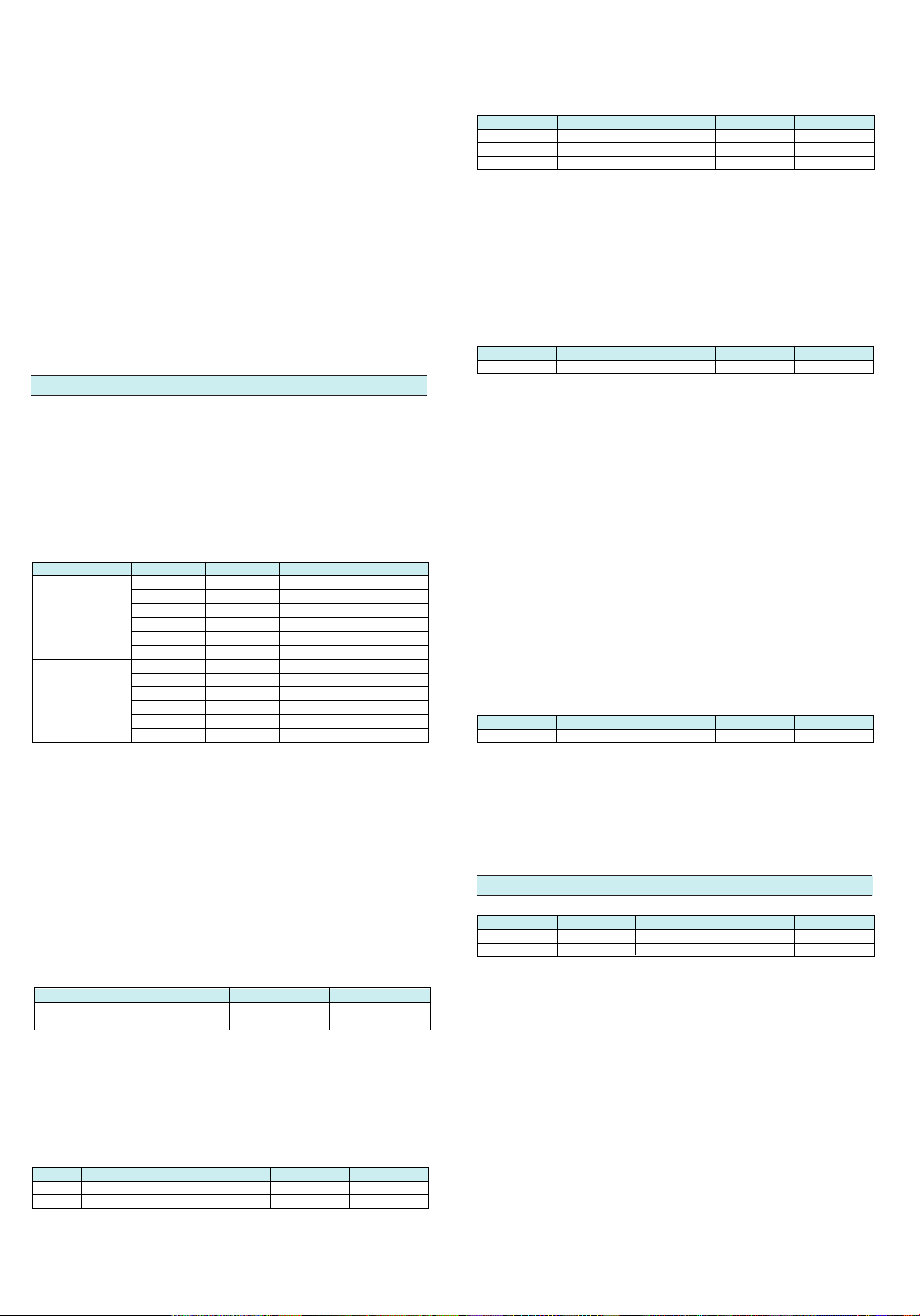
■ Model and Suffix Codes
DR230 Stand-alone model
Model Suffix code
DR231
Memory
-0
-1
Software
0
2
Input channel
Input
Power supply voltage
Power inlet, power cable
Additional specifications
The maximum allowable number for the / N , / C , / A4 and / R1 options is determined according
●
to the specified channel number.
10 ch: All options can be specified.
20 ch: All of them can be specified.
30 ch: 3 of them can be specified.
-1
-2
-3
1
2
3
4
Desk-top type hybrid recorder
No memory
3.5-inch FD
No DAQ 32 software
DAQ 32 software included
10 ch
20 ch
30 ch
Universal input, screw
Universal input, clamp
DCV/TC/DI input screw
DCV/TC/DI input clamp
100 to 240 VAC
-1
3-pin power inlet w/UL CSA cable
D
3-pin power inlet w/VDE cable
F
3-pin power inlet w/SAA cable
R
3-pin power inlet w/BS cable
S
Computing functions
/M1
Report function
/M3
GP-IB
/C1
RS-232C
/C2
RS-422/485 (screw)
/C3S
Ethernet
/C7
Power monitor for single phase
/N7
Power monitor for 3 phase
/N8
Alarm output module (A type 10 contacts)
/A4
2-point alarm output, remote control signal input, fail output, and chart end output
/R1
Internal illumination
/H1
Carrying handle
/H5
°F display
/D2
DC power supply (AC and DC power supply coexist)
/P6
Description
Must not coexist
Must not coexist
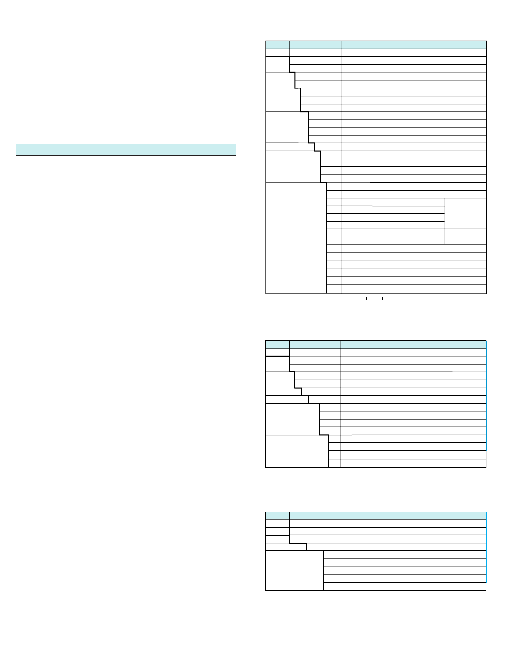
DR230 Expandable model
Model Suffix codes
DR232
Memory
-0
-1
Data conversion
0
2
Input
Power supply voltage
Power inlet, power cable
Additional specifications
Subunits and input/output modules must be ordered separately from the main unit.
●
●
The extersion cable must be ordered separately when the subunit is specified.
-00
-1
Desk-top type hybrid recorder
No memory
3.5-inch FD
No DAQ 32 software
DAQ 32 software included
Always -00
100 to 240 VAC
3-pin power inlet w/UL CSA cable
D
3-pin power inlet w/VDE cable
F
3-pin power inlet w/SAA cable
R
3-pin power inlet w/BS cable
S
Computing function
/M1
Report function
/M3
Internal illumination
/H1
°F display
/D2
Description
Subunit: DS400, DS600
Model Suffix codes
DS400
DS600
Type
-00
Power supply voltage
Power inlet, power cable
-1
4-module connection type subunit
6-module connection type subunit
Always -00
100 to 240 VAC
3-pin power inlet w/UL CSA cable
D
3-pin power inlet w/VDE cable
F
3-pin power inlet w/SAA cable
R
3-pin power inlet w/BS cable
S
With 3-pin inlet screw conversion terminal
W
Description
Configuration example of the expandable model
● 100 ch, 0.5 s universal input, with RS-232C and 20-ch alarm output
• DR230 expandable main-unit: DR232 × 1
• Sub unit: DS600 × 2
• Universal input module: DU100-11 or -12 × 10
• Communication module: DT300-21 (RS-232C) × 1
• Alarm output module: DT200-21 × 2
• Extension cable × 2
Page 4

Input modules
Model
10-channel universal input (DCV, TC, DI & RTD)
DU100-11
20-channel universal input (DCV, TC, DI & RTD)
DU100-21
30-channel universal input (DCV, TC, DI & RTD)
DU100-31
10-channel universal input (DCV, TC, DI & RTD)
DU100-12
20-channel universal input (DCV, TC, DI & RTD)
DU100-22
30-channel universal input (DCV, TC, DI & RTD)
DU100-32
10-channel DCV/TC/DI input
DU200-11
20-channel DCV/TC/DI input
DU200-21
30-channel DCV/TC/DI input
DU200-31
10-channel DCV/TC/DI input
DU200-12
20-channel DCV/TC/DI input
DU200-22
30-channel DCV/TC/DI input
DU200-32
10-channel mA input module
DU300-11
10-channel mA input module
DU300-12
Power monitor module for single phase
DU400-12
Power monitor module for 3 phase
DU400-22
10-channel strain input module (120 Ω)
DU500-12
10-channel strain input module (350 Ω)
DU500-13
10-channel strain input module (External bridge box)
DU500-14
10-channel pulse input
DU600-11
Digital input
DU700-11
Description
Required slots
1
2
3
1
2
3
1
2
3
1
2
3
1
1
1
1
2
2
2
1
1
Terminal profile
Screw
Screw
Screw
Clamp
Clamp
Clamp
Screw
Screw
Screw
Clamp
Clamp
Clamp
Screw
Clamp
Clamp
Clamp
Clamp
Clamp
NDIS
NDIS
Screw
Max. measuring period
0.5 s
2 s
2 s
0.5 s
2 s
2 s
0.5 s
2 s
2 s
0.5 s
2 s
2 s
0.5 s
0.5 s
2 s
2 s
0.5 s
0.5 s
0.5 s
0.5 s
0.5 s
I/O terminal module
Model
DT100-11
DT200-11
DT200-21
DT300-11
DT300-21
DT300-31
DT300-41
DI/DO module
(2-point alarm output, remote control signal input, fail/chart end output)
Alarm output module (4 transfer contacts)
Alarm output module (10 make contacts)
GP-IB module
RS-232C module
RS-422/485 module
Ethernet module
Description
Software
Model Description
DARWIN DAQ32 software
(Supports setup, simplified data logging and viewing,
and diagnosis and calibration functions. One package
DP120-13
of this software comes standard with the purchased
DR230 recorder if you specify the model code
specification for "software included.")
DARWIN DAQ32Plus software
(Supports setup, data logging and viewing, diagnosis
DP320-13
and calibration and tag setting functions.)
Enhanced multifunctional data logging software
DP350-13
Report software
DP380-13
"InTouch for DARWIN" data logging software for process
use
DP800- 1E
(Choices for the field: 1 = 40 channels; 2 = 120
channels; 3 = 300 channels)
The DP120 (
DAQ32
and neither can the combination of the DP350 enhanced multi-functional data logging software,
DP380 report software and DP800 InTouch for DARWIN software.
) and DP320 (
DAQ32Plus
) data acquisition software cannot be run simultaneously,
Applicable Operating System
Windows 95, Windows 98
or Windows NT4.0
Windows 95, Windows 98
or Windows NT4.0
Windows 3.1, Windows 95
or Windows 98
Windows 3.1, Windows 95
or Windows 98
Windows 95 or
Windows NT4.0
Optional accessories
Model
DV100-011
DV100-012
DV200-000
DV200-001
DV200-002
DV200-005
DV200-010
DV200-020
DV200-050
DV200-100
DV200-200
DV200-300
DV200-400
DV200-500
DV250-001
DV300-011
DV300-012
DV300-101
DV300-102
DV300-251
DV300-252
DV400-011
DV400-013
DV400-051
DV450-001
Extension module
Extension base unit
Extension cable (0.5 m)
Extension cable (1 m)
Extension cable (2 m)
Extension cable (5 m)
Extension cable (10 m)
Extension cable (20 m)
Extension cable (50 m)
Extension cable (100 m)
Extension cable (200 m)
Extension cable (300 m)
Extension cable (400 m)
Extension cable (500 m)
Cable adapter
Shunt resistor 10 Ω, for screw
Shunt resistor 10 Ω, for clamp
Shunt resistor 100 Ω, for screw
Shunt resistor 100 Ω, for clamp
Shunt resistor 250 Ω, for screw
Shunt resistor 250 Ω, for clamp
Rack mounting kit (DS400/DS600)
Rack mounting kit (DR230)
Power cable between DR expandable main unit and subunit
Strain converter
Description
Spares
Part No.
B9627AZ
B9627RY
B9627AY
●
10-color ribbon
Z-fold paper (30 m) (time axis:10 mm)
Z-fold paper (30 m) (time axis: 25 mm)
Standard accessories for the DR230
One Z-fold chart paper, one ink ribbon, instruction manuals
Excel, Windows, MS and MS-DOS are registered trademarks of Microsoft
Corporation, USA.
IBM and IBM PC/AT are registered trademarks of International Business
Machines Corp.
Lotus 1-2-3 is a registered trademark of Lotus Development Corporation.
AT-GPIB and GPIB-98 Turbo are registered trademarks of National
Instruments.
Ethernet is a registered trademark of Xerox Corporation.
Other company and/or product names are registered trademarks of the
respective companies.
Name
Order q'ty
1
10
10
External Dimensions (
266
(10.47)
25
(0.98)
If not specified, the tolerance is 63%. However, in case of less than 10 mm, the tolerance is 60.3 mm.
DR232 with DS600 subunit on the rear panel
438
(17.24)
(1.18)
)
Unit: mm (inches)
30
207
98.8
(8.15)
(3.89)
63.6
(2.50)
10 11.3 30
(0.39)
(1.97)
5060.2
(3.94)
10060.5
(11.77)
29961
0.2
6
(1.97)
50
6
(1.97)
5060.2
24.5
(0.97)
(0.24)
JIS ANS/EIA
0.97
480 61 (18.9) : JIS
482.6 61 (19) : ANS/EIA
Rack Mount
(0.45)
6.8
(0.27)
190.560.5
37.7
1 : Installed only for JIS-standard rack
2 and 3 : Removed for ANSI-or EIA-standard rack
Panel Surface
(1.18)
(7.5)
(10.47)
265.961
(1.48)
12 23
 Loading...