

Page 1
Page 2

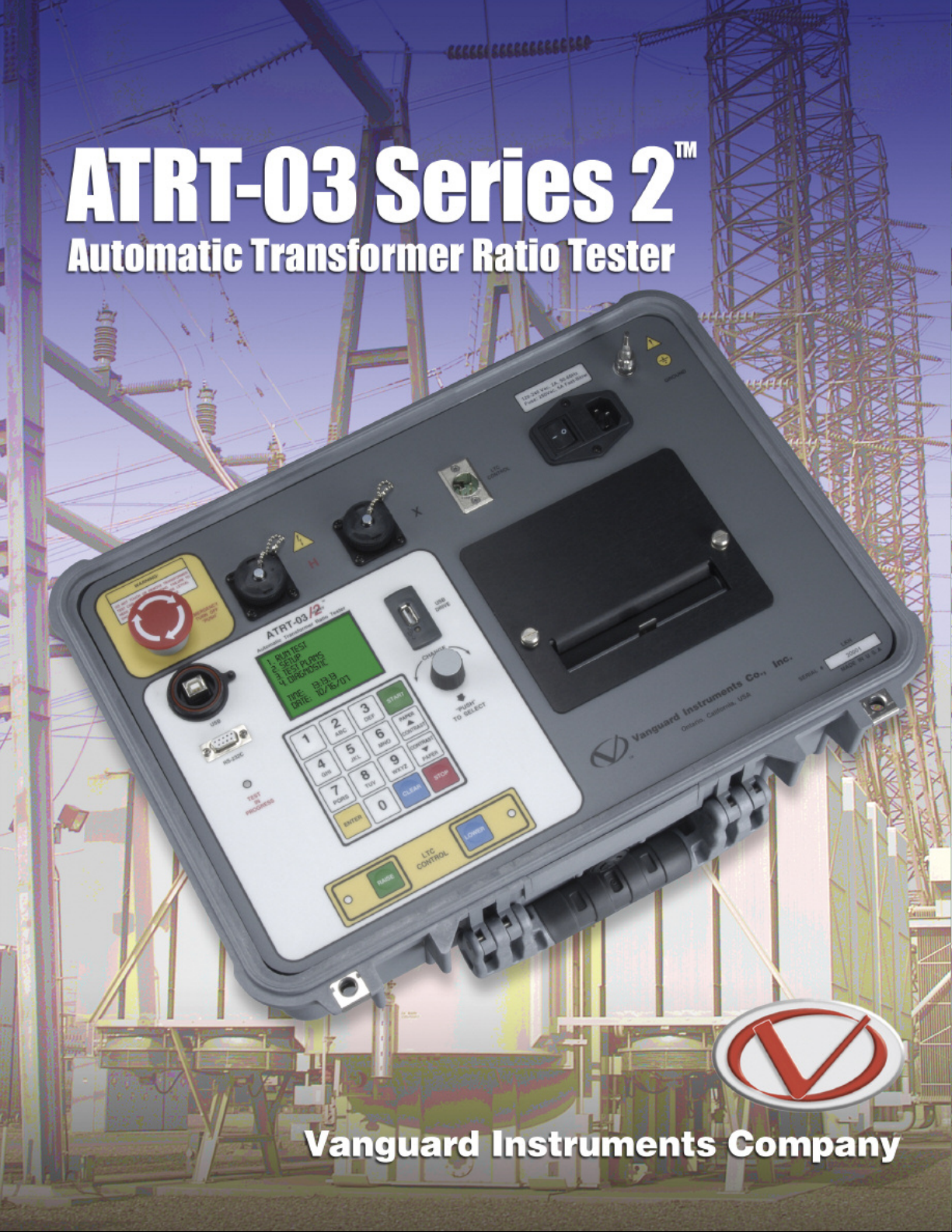
ATRT-03
Automatic 3-Phase Transformer Turns-Ratio Tester
The ATRT-03 S2 is Vanguard’s third generation, microprocessor-based, automatic, three
phase, transformer turns-ratio tester. This lightweight and rugged portable unit is
designed for transformer testing at utility power substations.
The ATRT-03 S2 determines the transformer turns-ratio using the IEEE C57.12.90 measurement method. The ATRT-03 S2 outputs an excitation test voltage to the transformer’s primary windings. The induced secondary voltage is sensed and the transformer turns-ratio is
calculated. The ATRT-03 S2 can measure turns-ratios from 0.8 to 15,000. The transformer
turns-ratio, excitation current, and phase-angle readings are displayed on the large backlit LCD. The built-in transformer type detection feature allows the ATRT-03 S2 to detect and
test 130 transformer types defined by ANSI, CEI/IEC and Australian standards.
The ATRT-03 S2 can be used as a stand-alone unit or can be computer-controlled. It can
be operated locally using its alpha-numeric keypad and rotary switch. Information is
displayed on a back-lit LCD screen (64 x 128 dot graphic) that is viewable in both
bright sunlight and low-light levels. Test reports can be printed in the field on the unit’s
built-in 4.5-inch wide thermal printer. The ATRT-03 S2 is capable of storing up to 112
test records and 128 test plans in Flash EEPROM memory. Test records or test plans can
be stored or transferred to and from a PC via the available interfaces (RS-232C port,
USB port, USB Flash drive port).
Transformer Test Voltage
To prevent an accidental wrong test-lead hook-up (e.g., when the operator reverses H and
X leads), the ATRT-03 S2 outputs a low-level test voltage to verify the hook-up condition
before applying the full test voltage to the transformer. Three test voltages (8 Vac, 40 Vac,
100 Vac) allow the ATRT-03 S2 to test CT’s and PT’s, as well as power transformers.
Auto-Detect Transformer Configuration
The ATRT-03 S2 can automatically detect 130 specific vector groups for different transformer types defined by ANSI, CEI/IEC, and Australian standards.
Automate
Transformer Test Plans
The ATRT-03 S2 can store up to 128 transformer test-plans in its Flash EEPROM. A test-plan
is comprised of the transformer nameplate voltages for each tap setting. The calculated
turns-ratio based on the nameplate voltages is compared with the measured turns-ratio. By
recalling a test plan, a transformer can be quickly tested and turns-ratio Pass/Fail reports
can be reviewed. Test plans can be created with the PC software and can be transferred to
the ATRT-03 S2 via the available interfaces (RS-232C port, USB port, USB Flash drive port).
Test Record Storage Capabilities
Up to 112 test records can be stored in the ATRT-03 S2’s Flash EEPROM memory. Each
test record may contain up to 33 turns-ratio, excitation current, phase angle and name
plate voltage readings. Test records can be recalled locally or transferred to a PC via the
available interfaces (RS-232C port, USB port, USB Flash drive port).
USB Flash Drive Interface
A built-in USB Flash drive interface provides a convenient method for transferring test
plans and test records to or from a USB Flash drive. The user can store up to 999 transformer test plans on a USB Flash drive. Test plans can be transferred from a PC to a USB
Flash drive, and then a specific test plan on the USB Flash drive can be transferred to
the ATRT-03 S2’s internal Flash memory. Up to 999 test records from the field can be
stored on a USB Flash drive. Test records stored in the ATRT-03 S2’s internal memory
can also be transferred to a USB Flash drive. The supplied PC software can then be used
to view the test records stored on the USB Flash drive.
Computer Interface
In computer-controlled mode, the unit can be controlled via the RS-232C or USB port
using the supplied PC software (Transformer Turns-Ratio Analyzer application provided
with each ATRT-03 S2). This Windows® XP/Vista-based software can be used to run a test
and to store test results on a PC. Test results can also be exported to Microsoft® Excel.
Thermal Printer
A built-in 4.5-inch wide thermal printer prints test results in a 14 point font for easy viewing. The printer and paper dispenser are mounted under the front panel for protection.
Transformer Load Tap Changer Control
Transformer tap positions can be changed remotely using the unit’s built-in transformer
load tap changer. This remote-controlled tap changer feature eliminates the need to
manually change a transformer’s step-up and step-down taps.
ATRT-03 S2 Input Power Sources
The ATRT-03 S2 can be powered from a single-phase 100-240 Vac 50/60 Hz power
source. A built-in safety ground detection circuit can detect and display a ground fault
problem with the AC input source.
ATRT-03 S2
Connections
TM
User Interface
The ATRT-03 S2 features a back-lit LCD screen (64 x 128 dot graphic) that is viewable
in both bright sunlight and low-light levels. The test results screen displays the transformer turns-ratio, excitation current, phase angle, and percentage error. The unit is
controlled via a rugged, 16-key, membrane keypad and a digital rotary switch.
Automatic Three-Phase Turns-
2
Page 3

the Tedious Procedure
of Transformer Turns-Ratio Testing
Ordering Information
TRT-03 Series 2, Three Phase Transformer Turns-Ratio Tester
A
ATRT-03 S2, Cables, PC Software Part No: ATRT-03S2
TRT-03 S2 Carrying Case Part No: ATRT-03S2 Case
A
.5-inch Printer Paper Part No: Paper - TP4
4
PC
▼
Printer
Output
USB and
RS-232C
Interfaces
Emergency
Turn-Off
ack-lit LCD Screen
B
(128x64 dot graphic)
Connector for
H Terminals
TC Control
L
Switches
ugged 16-Key
R
Membrane Keypad
U
Drive Interface
unction
F
Control Knob
SB Flash
LTC Control
Connector
Connector for
X Terminals
Power
Switch
.5-Inch Wide
4
Thermal Printer
Thermal
▼
Printer
Output
TYPE
PHYSICAL SPECIFICATIONS
OPERATING VOLTAGE
MEASUREMENT METHOD
TURNS-RATIO MEASURING RANGE
TURNS-RATIO ACCURACY
TEST VOLTAGES
EXCITATION CURRENT READING RANGE
PHASE-ANGLE MEASUREMENT
DISPLAY
PRINTER
COMPUTER INTERFACES
EXTERNAL DATA STORAGE
PC SOFTWARE
INTERNAL TEST RECORD STORAGE
INTERNAL TEST PLAN STORAGE
LOAD TAP CHANGER CONTACT
SAFETY
ENVIRONMENT
HUMIDITY
ALTITUDE
CABLES
OPTIONS
WARRANTY
SPECIFICATIONS
Portable, lightweight, automatic, 3-phase transformer turns-ratio meter
18”W x 7”H x 15”D (45.7 cm x 17.8 cm x 38.1 cm ); Weight: 20 lbs (9.0 kg)
100 – 240 Vac, 50/60 Hz
ANSI/IEEE C57.12.90
0.8 – 15,000
0.8 – 1,999: ±0.1%, 2,000 – 3,999: ±0.25%. 4,000 – 15,000: ±1% @ 8Vac
0.8 – 1,999: ±0.1%, 2,000 – 3,999: ±0.20%. 4,000 – 15,000: ±1% @ 40Vac
0.8 – 1,999: ±0.1%, 2,000 – 3,999: ±0.15%. 4,000 – 15,000: ±1% @ 100Vac
8 Vac @ 1Amp, 40 Vac @ 0.2 Amp, 100 Vac @ 0.1 Amp
0 – 2 Amperes; Accuracy: ±0.1 mA, ±2% of reading (±1 mA)
0 – 360 Degrees; Accuracy: ±0.2 degree (±1 digit)
Back-lit LCD screen (64 x 128 dot graphic display); Viewable in bright sunlight and low-light levels
Built-in 4.5-inch wide thermal printer
One RS-232C port, One USB port
One USB Flash drive interface port; Up to 999 transformer test records can be stored on a USB Flash drive (not included)
Windows® XP/Vista-based Transformer Turns-Ratio Analyzer application is included with purchase price
Can store 112 transformer test records internally. Each record holds the test record header and up to 33 readings.
Can store 128 transformer test plans internally. Test plans can be transferred to the unit from the PC via the RS-232C/USB port
or via the USB Flash drive interface
240 Vac, 2 Amps
Designed to meet UL 61010A-1 and CAN/CSA C22.2 No. 1010.1-92 standards
Operating: -10˚ to 50˚ C (15˚ to +122˚ F); Storage: -30˚ C to 70˚ C (-22˚ to +158˚ F)
90% RH @ 40˚C (104˚F) non-condensing
2,000m (6,562 ft) to full safety specifications
One 15-foot Single-phase set, One 15-foot 3-phase set, One 25-foot extension set, One safety ground, One USB, One RS-232C, cable bag
Transportation Case
One year on parts and labor
Note: All specifications herein are valid at nominal voltage and ambient temperature of +25°C (+77°F). Specifications are subject to change without notice.
Vanguard Instruments Company
Reliability Through Instrumentation
RVFeb10
Page 4

Vanguard Instruments Company, Inc.
Vanguard Instruments Co., (VIC), was founded in 1991.
Currently, our 28,000 square-foot facility houses Administration,
Design & Engineering, and Manufacturing operations. From its
inception, VIC’s vision was, and is to develop and manufacture
innovative test equipment for use in testing substation EHV circuit
breakers and other electrical apparatus.
The first VIC product was a computerized circuit-breaker analyzer, which was a resounding success. It became the forerunner of
an entire series of circuit-breaker test equipment. Since its beginning, VIC’s product line has expanded to include microcomputer-based, precision micro-ohmmeters, single and three-phase
transformer winding turns-ratio testers, winding-resistance
meters, transformer tap-changing controllers, megaohm resistance meters, and a variety of other electrical utility maintenance support products.
VIC’s performance-oriented products are well suited for the utility industry. They are rugged, reliable, accurate, user friendly, and
most are computer controlled. Computer control, with innovative
programming, provides many automated testing functions. VIC’s
instruments eliminate tedious and time-consuming operations,
while providing fast, complex, test-result calculations. Errors are
reduced and the need to memorize long sequences of procedural steps is eliminated. Every VIC instrument is competitively
priced and is covered by a liberal warranty.
Vanguard products are available from:
Vanguard Instruments Company, Inc.
1520 S. Hellman Ave. • Ontario, California 91761 USA • P 909-923-9390 • F 909-923-9391
www.vanguard-instruments.com
 Loading...