

Page 1
Constant beamwidth over wide band of operation and typical
radiation pattern of log periodic antennas make these
antennas ideally suited for generating uniform fields over a
large area.
Several high gain arrays and broadband antennas which
can handle power levels in excess of several kilowatts are
available for immunity testing per IEC 1000-4-3, MIL-STD
and SAE requirements. All log periodic antennas from ARA
TECH offer a cross polarization rejection in excess of 20dB,
especially suited for measurements per CISPR 16-1.
Four types of log periodic antennas for EMC emission and
immunity testing are offered. These are LPD and LPV
series linearly polarized antennas, LPC series dual
polarized antennas, and LPA series high gain arrays.
LINEARLY POLARIZED
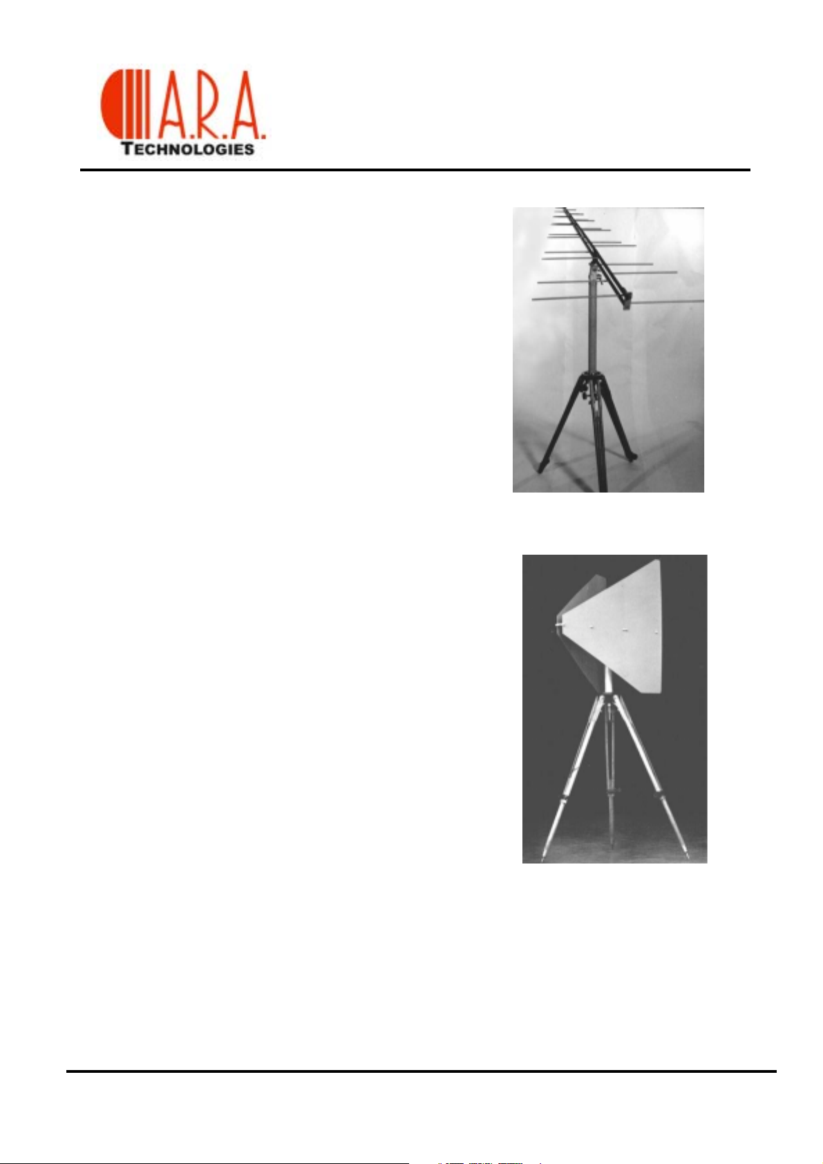
LPD series antennas are linearly polarized, log periodics
designed to transmit and receive signals over a broad
frequency range. These antennas are characterized by a
high front-to-back ratio, excellent SWR and medium power
gain at all frequencies in the band. Polarization adjustment
is possible in any plane, with a universal joint.
LOG PERIODIC DIPOLES
20 MHz - 18 GHz
TRANSMIT - RECEIVE
LPD-2010/C
High quality aluminum construction with all stainless steel
hardware make for a lightweight, high strength antenna that
will provide years of trouble-free operation. For emission
testing or low power transmit applications, an assortment of
low profile LPDs are available. These antennas are
constructed on cost-effective copper clad dielectric
materials. LPDs exhibit the same performance standards as
our other antennas, but with cost savings to the customer.
Standard LPD antennas are intended for relatively
permanent installations. LPD series antennas operating
below 400 MHz are also supplied in a kit form for storage
and transportation. Antennas in the kit form assemble
easily with minimum tool requirements.
LPV-2010
The Vee configuration, LPV series log periodic antennas give greater power gain than that obtainable
with a planar log-periodic antenna of the same length and taper. The short length of the LPV-2010/C
antenna restricts the movement of the active region as a function of frequency to a relatively small
volume, which is desirable in RFI measurements.
Page 2
LOG PERIODIC DIPOLES
20 MHz - 18 GHz
TRANSMIT - RECEIVE
SPECIFICATIONS
FREQUENCY TYP. GAIN TYP. FRONT/ VSWR POWER POLARIZATION
LPD-2010/C
LPV-2010/C
LPD-8270
LPD-2027
LPD-8130/A1
LPD-1011
LPD-2020/A
LPD-3500
LPD-820/A
LPD-118
*Specifications from 35 to 220 MHz
200 - 1000 MHz 7.5 20 1.5 : 1 1 kW 1.4 kW Linear
200 - 1000 MHz 7.0 20 2 : 1 100 W 100 W Linear
80 - 2700 MHz 6.0 20 2 : 1 2 kW 2.6 kW Linear
200 - 2700 MHz 6.0 20 2 : 1 50 W 75 W Linear
80 - 1300 MHz 6.0 20 2.5 : 1 1.5 kW 2 kW Linear
100 - 1100 MHz 6.0 20 2 : 1 1 kW 1.4 kW Linear
200 - 2000 MHz 6.5 20 2 : 1 250 W 500 W Linear
300 - 5000 MHz 5.0 15 2 : 1 5 W 25 W Linear
750 - 2000 MHz 6.5 20 2 : 1 125 W 300 W Linear
1.0 - 18.0 GHz 7.0 18 2 : 1 5 W 25 W Linear
ELECTRICAL Impedance: 50 ohms
I
NDIVIDUALLY CALIBRATED
(DBI.) BACK (DB) CW PEAK
LPD-118
LPD-3500
MECHANICAL
BOOM
LENGTH
LPD-2010/C
LPV-2010/C
LPD-8270
LPD-2027
LPD-8130/A1
LPD-1011
LPD-2020/A
LPD-3500
LPD-820/A
LPD-118
51” 29” 4/1.8 Aluminum Center N Female Yes
27” 15”/29” 8/3.6 Copper Clad End BNC - F N/A
67” 82.5” 4” Aluminum Center N Female Yes
34” 4 / 27.5 2.5 / 1.1 Aluminum Center N Female N/A
64” 77” 15 / 7 Aluminum Center N Female N/A
60” 60” 7.6 / 3.5 Aluminum Center N Female Yes
45” 30” 4 / 1.8 Aluminum Center N Female N/A
16.5” 20” 1.0 / .45 Copper Clad Center SMA F em al e N/A
10” 7.5” / 7.5” 4 / 1.8 Aluminum End BNC - F N/A
9” 8” 1 / .45 Copper Clad End SMA Female N/A
** For ordering in kit form, add a subscript "K" at the end of the model number
WIDTH /
HEIGHT
WEIGHT
(LBS/KG)
CONSTRUCTION MOUNTING CONNECTOR
KIT **
TYPE
Page 3
LOG PERIODIC DIPOLES
20 MHz - 18 GHz
TRANSMIT - RECEIVE
LPD-3500
Antenna Factor, Gain and Power required for 10
V/m field strength at 1 m
Frequency
(GHz)
0.3 15.2 4.6 1.16
0.4 16.2 6.1 .80
0.5 18.5 5.7 .90
0.6 19.8 6.0 .84
0.7 21.2 5.9 .86
0.85 22.5 6.3 .78
1.0 24.1 6.1 .82
2.0 32.2 4.1 1.29
3.0 35.5 4.3 1.24
4.0 35.9 6.4 .76
5.0 39.4 4.8 1.10
Antenna Factor, Gain and Power
required for 10 V/m field strength at 1 m
Frequency
(GHz)
1 23.4 6.7 .69 200 9.0
2 31.2 5.0 1.04 250 10.5
3 33.8 6.0 .84 300 11.6
4 34.3 8.0 .53 400 13.9
5 37.1 7.2 .65 500 15.5
6 37.2 8.6 .46 600 17.3
7 38.9 8.2 .50 700 19.2
8 40.1 8.2 .51 850 20.1
9 39.7 9.6 .36 1000 22.4
10 40.9 9.3 .39
11 42.5 8.6 .46
12 43.3 7.9 .47
13 44.7 7.8 .55
14 44.1 9.0 .41
15 45.3 8.5 .48
16 45.5 8.8 .44
17 47.3 7.6 .59
18 50.5 4.9 1.09
AFE
(dB m
AFE
(dB m
-1
LPD-118
Gain
)
(dBi)
-1
Gain
)
(dBi)
Power
(Watts)
Power
(Watts)
Antenna Factor, Gain and
Frequency
required for 10 V/m field strength at 3 m
Frequency
(MHz)
LPD-1011
Power required for 10
V/m field strength at 1 m
AFE
(MHz)
100 5.2 5.0 1.05
200 9.8 6.4 .75
250 9.9 8.3 .49
300 12.3 7.5 .60
400 15.6 6.7 .72
500 16.2 8.0 .53
600 17.8 8.0 .53
700 20.3 6.8 .69
850 22.2 6.6 .73
1000 23.1 7.1 .65
LPD-2010/C
Antenna Factor, Gain and Power
AFE
(dB m
(dB m
-1
)
-1
Gain
)
(dBi)
Gain
(dBi)
7.2 5.7
7.6 5.1
8.1 4.6
8.3 4.4
8.7 4.0
8.4 4.2
7.9 4.8
8.7 4.0
7.8 4.9
Power
(Watts)
Power
(Watts)
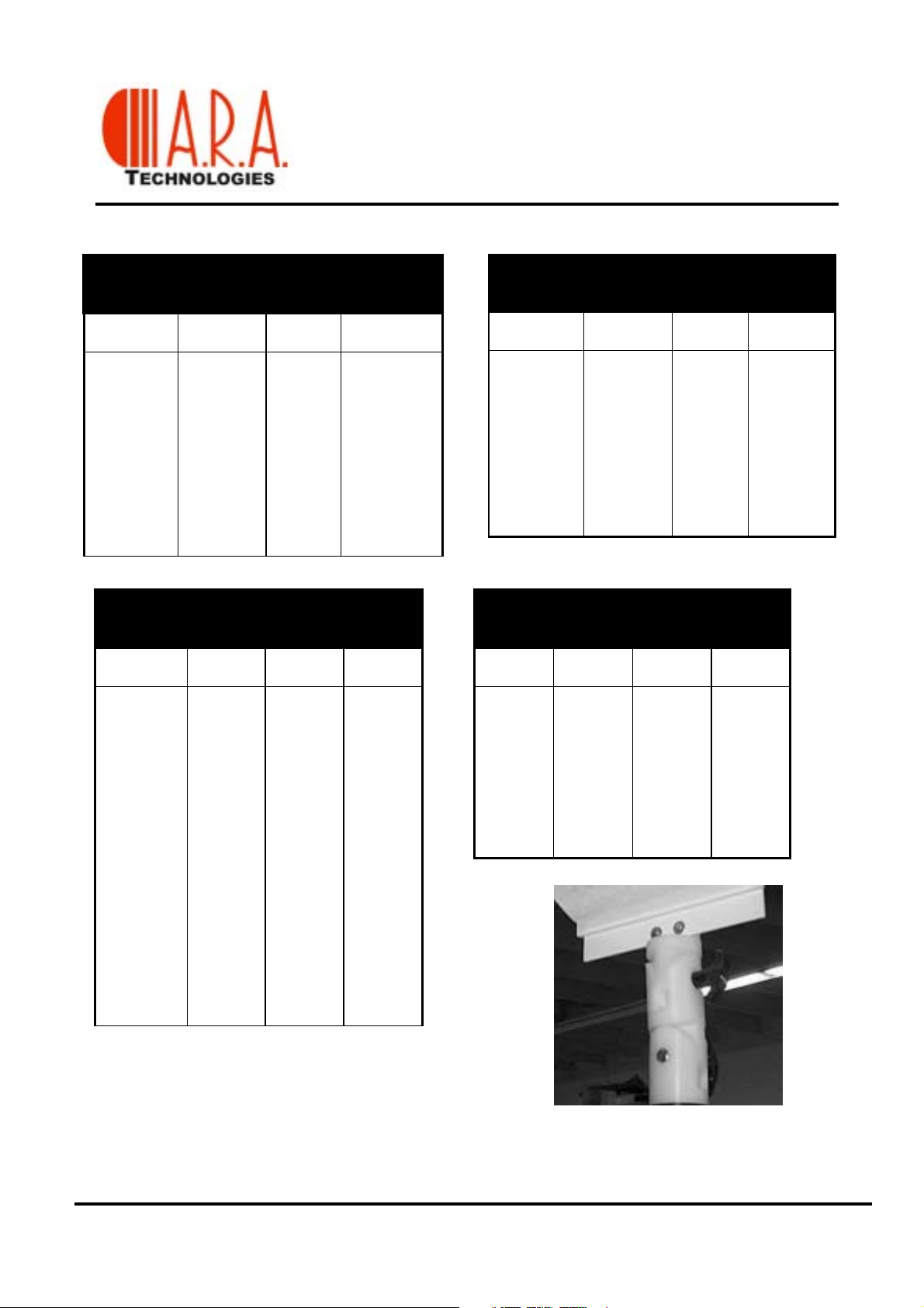
The LPD series universal joint allows for the
polarization and tilt adjustments of LPD series
antennas.
LPD S
ERIES UNIVERSAL JOINT
Page 4

LPD-8130/A1
TYPICAL ANTENNA FACTOR AND GAIN
FREQUENCY
(MHZ)
80 2.4 5.9
100 3.8 6.4
150 7.3 6.5
200 9.5 6.8
250 11.2 7.0
300 12.5 7.3
400 14.8 7.5
500 16.1 8.1
600 18.0 7.8
700 19.9 7.2
850 20.7 8.1
1000 21.5 8.7
1100 23.4 7.7
1200 24.4 7.4
1300 26.1 6.4
AFE
(dBi M
-1
(dBi)
)
GAIN
LOG PERIODIC DIPOLES
TRANSMIT - RECEIVE
LPD-820/A
LPD-8130/A1
TYPICAL E-FIELD ANTENNA FACTOR AND GAIN
FREQUENCY
(MHZ) AFE
200 9.6 6.7
250 11.2 7.0
300 12.7 7.1
400 14.8 7.5
500 16.2 8.0
600 17.6 8.2
700 19.7 7.4
850 21.0 7.8 21.0 7.8
1000 22.5 7.7 22.5 7.7
1100 23.6 7.5 23.6 7.5
1200 25.6 6.2 25.6 6.2
1300 26.4 6.1 26.4 6.1
1400 26.3 6.9 26.3 6.9
1500 26.5 7.3 26.5 7.3
1600 27.8 6.5 27.8 6.5
1700 28.2 6.6 28.2 6.6
1800 29.0 6.3 29.0 6.3
1900 29.9 5.9 29.9 5.9
2000 31.7 4.6 31.7 4.6
M
ODEL
(dB
LPD-820/A M
GAIN
-1
M
(dBi)
)
ODEL
AFE
(dB
LPD-2020
-1
M
)
GAIN
(dBi)
Page 5

LOG PERIODIC DIPOLES
HIGH POWER, HIGH FIELDS
Two different models are available for generating high fields below 50 MHz. LPD-220s are
designed to operate from 20 MHz to 200 MHz. The LPD-220/A10 and LPD-220/A5 can handle
input powers up to 10 KW and 5 KW, respectively.
The rear elements of the LPD-220s are truncated and loaded to reduce the overall size of the
antenna. Loaded elements at the low end simulate the gain of a full size log periodic antenna. A
wheeled pedestal is supplied to move this large antenna from one place to another. Antenna
polarization may be adjusted manually or remotely using an optional pedestal, model AS-220/T.
SPECIFICATION
INPUT IMPEDANCE: 50 ohms
VSWR: 3.5:1
LPD-220/A10 LPD-220/A5**
F
REQUENCY
G
AIN (DBI
P
OWER (K
B
OOM LENGTH
W
IDTH
H
EIGHT
C
ONNECTOR
• * Specifications from 35 to 220 MHz
• ** For 2kW power rating, order Model LPD-220/A2
)
W)
20-200 MHz 20-220 MHz
6.0* 6.0*
10 5
153” 153”
140” 136”
56” 56”
EIA 1-5/8” SC Female
LPD-220/A5
LPD-220/A5 - Typical VSWR
VSWR
CH 1: A -M 1.446 SWR
1.00 / REF 2.000 SWR
STRT + .0100 GHz MKR + .2200 GHz STOP
Page 6

LOG PERIODIC
DIPOLE ARRAYS
LPA series antennas are log periodic dipole arrays comprising of two or more log periodic dipole
antenna elements. All LPAs are designed for medium to high gain and high cross-polar rejection.
These antennas are ideally suited for generating high fields required for immunity testing.
Two-element log periodic dipole arrays, such as the LPA-8200, LPA-2201, and LPA-2020, offer
flat gain over a large bandwidth and low VSWR similar to the performance of an ordinary log
periodic dipole antenna. This is extremely useful in generating maximum field strength uniformly
over a large test area. A two-element array has 2 to 3 dB higher gain relative to an ordinary log
periodic dipole antenna. All two element arrays are optimized for identical beamwidths in both E
and H-planes
The LPA-2020/A3 is supplied with a 7/16 connector to handle high input power levels in excess of
3 kW.
.
LPA-820/8
SPECIFICATIONS
I
MPEDANCE
VSWR: 2 : 1 C
C
ONSTRUCTION
LPA-8200
LPA-2020/A3
LPA-2201/A1
LPA-2201/A2
LPA-820/8
M
ODEL
: 50
OHMS,NOMINAL
: A
LUMINUM
F
220 - 1000 12 1 kW 58" x 30" x 33" Rear 20 / 9
220 - 1000 12 2 kW 58” x 30” x 33” Rear 20 / 9
800 - 2000 16 - 19 500 W 24" x 40" x 40" Rear 30 / 14
REQUENCY
(MHZ)
G
AIN
(DBI)
P
OWER
CW
80 - 2000 9 2 kW 88” x 90” x 75” Rear 36 / 16
200-2000 9-10 3 kW 38” x 36” x 38” Rear 12 / 6
F/B R
ATIO
ONNECTOR
LPA-2201/A2
WITH ADJUSTABLE HEIGHT MAST
AND POLARIZATION ADJUSTMENT
: 20 DB
: N
D
IMENSIONS
LXWXH
MINIMUM
FEMALE
M
OUNTING
W
EIGHT
(
LBS/KG
)
Page 7

LOG PERIODIC DIPOLES
DUAL POLARIZED
DUAL POLARIZED
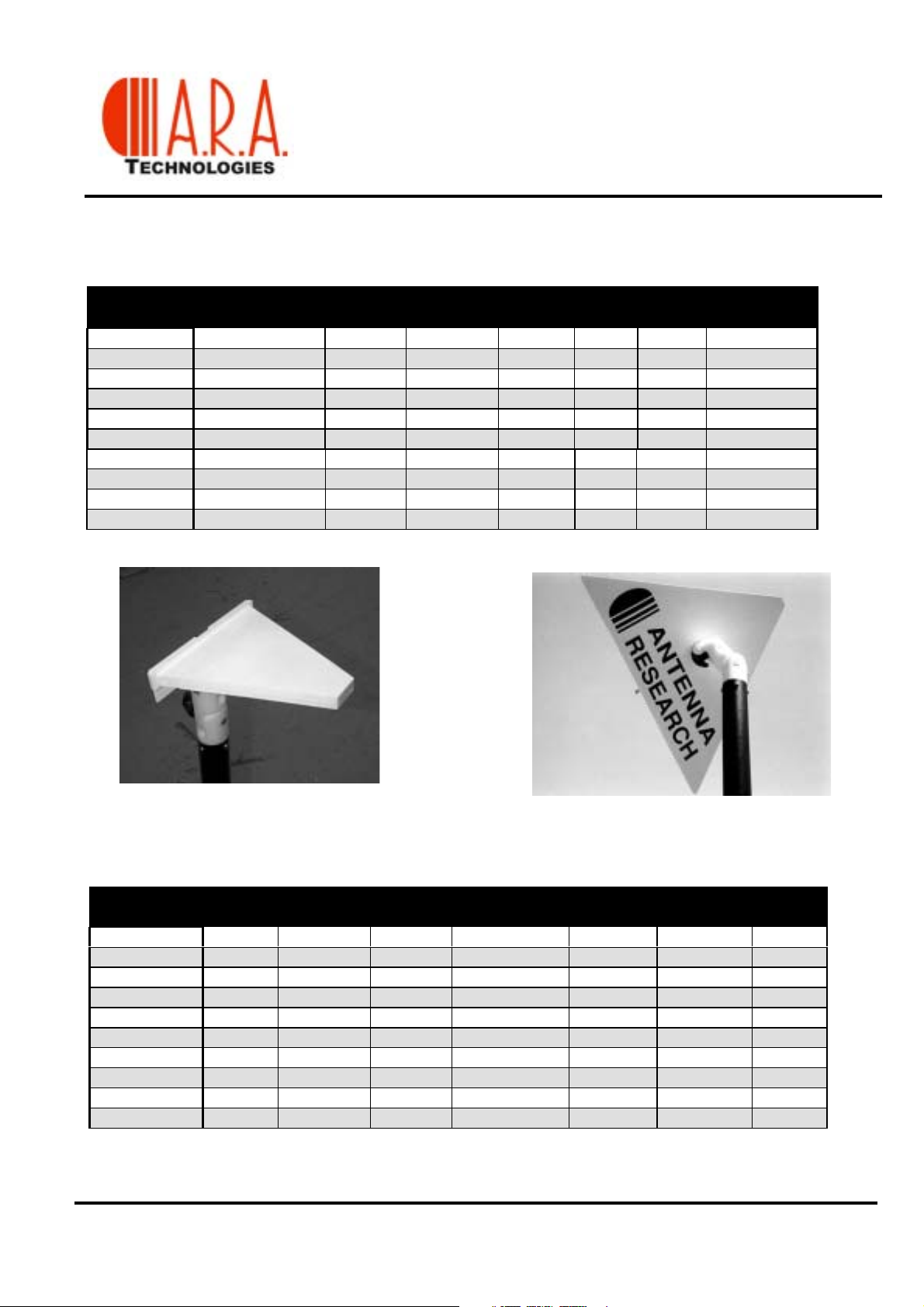
LPC series antennas are comprised of two planar log periodic structures on a common axis. Standard LPC
antennas are supplied with two output connectors. Switch assemblies and switch control units are available for
use with LPC antennas to yield vertical, horizontal, right circular, or left circular polarizations. These antennas
are characterized by a high front-to-back ratio, excellent SWR, and medium power gain at all frequencies in the
band.
S
PECIFICATIONS
IMPEDANCE: 50
VSWR: 2 : 1 T
ODEL
M
LPC-3100/C
LPC-3540
LPC-8100/C
LPC-2010/C
LPC-2020/C*
LPC-560*
LPC-820/C*
* A Radome is available for outdoor installation. ** Height with Mast
OHMS,NOMINAL
YPICAL
REQUENCY
F
(MHZ) (DB)
30 -1000 6.0 500 W 110 / 50 N female 210" x 200" x 200"
35 - 400 5.0 10,000 W 320 / 160 82 G female 204” x 168” x 208” **
80 - 1000 6.5 1 kW 28 / 12.6 N female 88” x 75" x 75"
200 - 1000 6.0 1 kW 10 / 4.5 N female 50" x 30" x 30"
200 - 2000 6.0 200 W 14 / 6.5 N female 50" x 30" x 30"
500 - 6000 6.0 40 W 3 / 2 SMA female 21” x 12” x 12”
800 - 2000 8.0 125 W 9 / 4.0 BNC female 12" x 8" x 8"
G
F/B RATIO: 20 DB POLARIZATION: D
MINIMUM ISOLATION: 20 DB
AIN
POWER WEIGHT C
CW
(
LBS/KG
) LXWXH
ONNECTOR
UAL
IMENSIONS
D
LPC-3100
LPC-3540/C
LPC-8100/C - TYPICAL E-FIELD ANTENNA FACTOR AND GAIN
REQUENCY
F
AFE (DB
AIN (DBI
G
M
)
(MHZ)
-1
)
80 90 100 200 250 300 400 500 600 700 850 1000
1.4 2 3.1 9.0 11.1 12.5 15.9 15.5 17.8 20.2 22.1 23.0
6.9 7.3 7.1 7.2 7.1 7.3 6.4 8.7 8.0 6.9 6.7 7.2
LPC-2010/C
LPC-8100 & LPC-560
 Loading...