

Page 1

ACTERNA TEST & MEASUREMENT SOLUTIONS
ANT-5
SDH Access Tester up to STM-16
Key Features
• Smallest and lightest test solution (only 2.2 kg) for interfaces from
1.544 Mbps up to 2.5 Gbps
• Optical testing at dual wavelengths from STM-1/OC-3 up to
STM-16/OC-48
• Electrical testing at DS1, E1, E3, DS3, E4,STM-0,and STM-1/OC-3
• Full analysis of concatenated mappings with SDH/SONET signals
• In-depth PDH analysis with Sa bit generation and flexible mux/
demux test configuration
• Optical power measurements for verification of physical layer
integrity
• ATM functionality for service verification of ATM, 3G, and UMTS
networks (provided via T-carrier, PDH,SDH, or SONET)
• In-line Monitor and Instrusive Thru Modes for traffic analysis and
network testing
• ECL/NRZ port enables non-intrusive direct monitoring of optical
networks
The access network explosion
The modern communications market is challenging network operators in new
ways. Because growth from traditional voice services has declined, operators must
find new ways to carry more data traffic in order to maintain their revenue
stream. However, bandwidth bottlenecks in the access and metro networks have
prevented many new high-speed, high-bandwidth services from being efficiently
deployed.
Field technicians, who are tasked with installing and maintaining these networks,
must learn how to test a wide variety of technologies while they strive to reach
new levels of productivity. To perform these tasks, technicians require an
increased number of pieces of equipment and additional training to operate each
device effectively.
Additionally, operators must be able to manage the conflicting demands of
technicians, who need the proper equipment and training to do their jobs, and
executives, who are keeping close control on capital expenses and operating costs.
The ANT-5 rises to the challenge
JDSU effectively meets the challenges faced by network operators with the JDSU
ANT-5 SDH Access Tester. Designed for field operations, the small, rugged,
battery-operated ANT-5 streamlines installation and maintenance testing. Its
advanced features and automated functions enable technicians to perform tests
quickly and effectively. And, with SDH, PDH, SONET, and ATM combined into
a single compact unit, capital investment and training expenses are reduced,
minimizing business costs.
NORTH AMERICA: 800 498-JDSU (5378) WEBSITE: www.jdsu.comWORLDWIDE: +800 5378-JDSU
Page 2
2
STM-16
STM-4
STM-1
AUG 16
AUG 4
AUG 1
AU-4-16c
AU-4-4c
AU-4
VC-4-16c
VC-4-4c
VC-4
C-4-16c
C-4-4c
C-4
C-3
TUG-3 TU-3
VC-3
AU-3
VC-3
TUG-2
DS3: 44736 kbps
E3: 34368 kbps
x1
STM-0
x1
x1
x1
x1
x1
x4
x3
x4
x7
x3
x1
C-12TU-12 VC-12
x3
C-11TU-11 VC-11
x4
E4: 139264 kbps
x7
*1, *3: 2396160 kbps
*1: 599040 kbps
E1, *2: 2048 kbps
E1, *2: 1544 kbps
Pointer processing
Multiplexing
Aligning
Mapping
Concatenated option only
AU-3 mapping option only
STM-16 option only
*1
*2
*3
SDH
ANT-5 SDH ACCESS TESTER
The portable solution
The ANT-5’s compact, robust design is
ideal for field and central office
applications. The convenient, built-in
stand and comfortable carry strap
enable hands-free testing in any
location. And, its extended battery life
allows for testing even when AC
power is not on hand.
Optional carrying cases protect the
ANT-5 when technicians travel
between sites and provide a safe and
convenient place for storing cables and
accessories.
Simplest handheld to learn
Access technicians need a tester that
can simplify their key tasks without
extensive training. With its large color
screen, graphical user interface (GUI),
and ergonomic keypad, the ANT-5 is
the simplest handheld to learn and use
on the market today. Other features
include:
– Labelled LEDs that show current
and historical alarms
– OK results summary and pass/fail
results screen displays
– Auto-save of test results
– Fast store and recall of key network
configurations
– Auto-configuration detects actual
signal structure
– Automatic testing
Easiest to use
Technicians prefer instruments that
are the easiest to use, so that they can
concentrate their efforts on measurement tasks rather than on the complex
operation of the instrument itself.
The ANT-5 is the most complete
instrument, with all of the necessary
interfaces already built-in, including
T1 Bantam, E1 balanced, and E1
unbalanced up to optical interfaces
with STM-16/OC-48. It covers Tcarrier, PDH, SDH, and SONET
technology, all in one instrument.
The ANT-5’s world-class ease-of-use is
based on a clearly structured operation
concept: SETUP – RESULTS –
ACTIONS.
The ANT-5 offers three operation
modes to cover all necessary field
applications, including intrusive, nonintrusive, and monitoring modes. An
important feature is the ECL/NRZ
port for monitoring optical circuits at
electrical monitor points provided by
network elements (STM-1/-4/-16).
The navigation key allows for simple
operation, and the keyboard supports
the easy input of comments, file
names, etc.
The internal memory can hold
hundreds of files. For result analysis
and report generation, the ANT-5
allows for the easy transfer of files to
the instrument’s Compact Flash
Memory Card (CF card). In addition,
the Mircrosoft® Windows®-based Offline Viewer provides simple results
analysis.
For report generation, the Off-line
Viewer print functions can be used,
supporting any of your desktop
printers in your Windows
environment.
Application selection
The ANT-5 application menu opens
direct access to the following
applications:
– Performance Analysis (according to
ITU-T, ANSI)
– Repetitive BERT (radio link application)
– Automatic Protection Switching (APS)
– Service Disruption Measurements
– OH Capture
– Round Trip Delay Measurements
(RTD)
The corresponding results are directly
accessible in the results page structure.
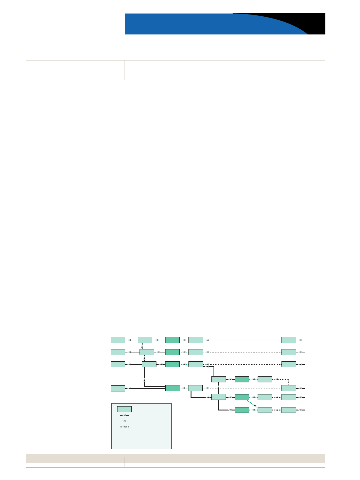
Figure 1: STM mapping structure (SDH systems)
Page 3
3
STS-1
STS-3c
STS-12c
STS-48c
VT-2 SPE
VT-Group
E3: 34368 kbps
x1, x4
x1
x1, x4, x16
x3, x12, x48
x7
x1
x3
E1: *2 2048 kbps
DS3: 44736 kbps
STS-48c SPE
STS-12c SPE
STS-3c SPE
STS-1 SPE
STS-N
OC-N
*1: 599040 kbps
*1, *3: 2396160 kbps
E4: 139264 kbps
x4
DS1: *2 1544 kbps
VT-2
VT-1.5 VT-1.5 SPE
N = 3, 12, 48
Pointer processing
Multiplexing
Aligning
Mapping
Concatenated option only
VT mapping option only
OC-48 (STM-16) option only
*1
*2
*3
SONET
ANT-5 SDH ACCESS TESTER
The access technicians’tool of
choice
The ANT-5 provides all of the
transmission test functions required in
today’s access networks:
– Optical power measurement
– Bit error rate testing
– G.821, G.826, G.828, G.829, ANSI,
M.2100, and M.2101 analysis
– Received signal offset measurement
– Transmit signal offset and generation
– Tabular and graphical event recording
Extensive SDH/SONET features
The ANT-5 is loaded with SDH and
SONET test features covering all
installation and maintenance tasks up
to 2.5 Gbps:
– STM-0e, STM-1e/STS-3 interface
– STM-1/OC-3 to STM-16/OC-48
optical ports at dual wavelengths
(1310/1550 nm)
– Auto-configuration
– Anomaly generation and analysis
– Defect generation and analysis
– SOH/POH generation and analysis
(HEX or clear text format)
– Pointer generation and analysis
– Path trace generation and analysis
– Tandem connection monitoring
(TCM) generation and analysis
– APS/service disruption measurements
– RTD measurements
– Automatic tributary scanning
– K-byte capture
Full PDH support
From 1.5 Mbps to 140 Mbps,
including nx64 Kbps, the ANT-5 can
test all PDH tributaries and legacy
PDH hierarchy transmission systems
using high-level functions that include
E1 Sa bit generation and display.
T-carrier support
The ANT-5 is also equipped with a
standard T1 Bantam interface and
supports DS1 and DS3 interfaces and
structures.
In addition, the multiplexer/
demultiplexer (mux/demux) option
now supports M13 framing (DS1/DS3)
and allows for 64 K channel analysis.
ATM service verification
UMTS network rollout and ADSL
growth is increasing the use of ATM in
the access network. The ANT-5 enables
the installation and maintenance of
ATM carried over PDH, SDH, and
SONET networks that include:
– DS1, STS-1 SPE, DS3
– E1, E3 (G.832), E4
– VC-4/STS-3c SPE
– VC-4-4c/STS-12c SPE
PVC cells can be generated over UNI
and NNI with CBR and VBR traffic
load profiles up to STM-4c rates.
Service quality can be checked using
BER or O.191 measurements. Link and
channel performance can be monitored
while traffic statistics are recorded.
Channel Explorer scans automatically
for active VCI/VPI and displays the
result in tabular form.
3G Network & DSLAM
Enhanced Support (Options)
With the 3G roll-out and expansion
coupled with the increase in ATMDSLAMs to support Triple Play, there is
a need for enhanced ATM support and
IP-Over ATM capability. The ANT-5
enables installation and maintenance of
these networks with extended ATM
capability:-
– AAL2 Generation and analysis
– AAL5 Generation and analysis
– IP-Ping (Send Ping and Reply To Ping
– IP-Trace Route
– Inverse Multiplexing in ATM(IMA)
monitoring
The Traffic Channel analysis allows the
scanning of a range of VPI/VCI
channels and reports on the type of
traffic and the nature of the traffic.
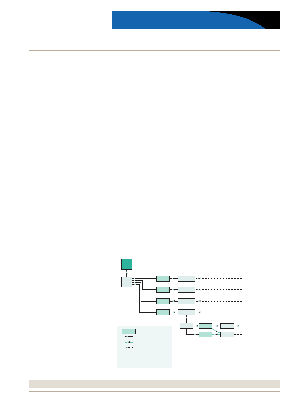
Figure 2: STS mapping structure (SONET systems)
Page 4

4
ANT-5 SDH ACCESS TESTER
Simple test and results
management
Due to its built-in Ethernet port, CF
card port, and printer port, the ANT-5
can integrate more effectively and
simply with day-to-day operations.
– Export standard test setups to other
ANT-5s or PCs via the CF card
– Exchange results over LANs using
Windows-based PCs
– Print test reports directly via the
serial interface or from a PC using
the Off-line Viewer software
Result evaluation (Off-line
Viewer)
Results (in ANT-5 format) can be
loaded, analyzed, and printed by any
Windows-based PC using the ANT-5
Off-line Viewer software.
Off-line Viewer enables the generation
of specific setups with easy
downloading to the instrument. The
user interface can be displayed in the
following languages: English, German,
French, Italian, Spanish, Portuguese,
and Chinese. This Windows-based
software, included with each
instrument, can also be used for
training purposes, providing an
excellent product simulation.
Remote GUI
Remote operation is achieved by
establishing a suitable communications link over an Ethernet LAN.
Once the link has been successfully set
up, the PC/laptop can communicate
with the ANT-5 using the supplied
version of the ANT-5 GUI faceplate.
Advanced remote testing
capability
The ANT-5 also provides an advanced
remote testing capability over
Ethernet. As a result, technicians can
poll instruments remotely from their
offices, simplifying long-term
commissioning and maintenance tests
and dramatically reducing travel time
and costs. Test results can be saved to
any network hard disk or printed from
any network printer for convenient
analysis.
Flexible,cost-effective platform
The ANT-5’s flexible design enables it
to be adapted quickly to operators’
changing requirements. In addition, its
field upgradeable capability, provided
by the Compact Flash port, enables
technicians in the field to installsoftware in minutes.
Hardware upgrades can be purchased
to add optical bandwidths or
wavelengths. This protects the initial
investment and reduces additional
training expenses while allowing
operators to match capital expenditures to network rollout plans.
The ANT-5 is an industry-leading
access tester that sets new standards for
portability, ease of use, and
adaptability. It is the ideal device for
field technicians who need to test a
range of SDH, PDH, SONET, and ATM
digital links both onsite and from a
remote location. As a result, the
ANT-5 provides a significant
advantage for companies wishing to
optimize quality of service using a costeffective, industry-proven solution.
Figure 3: View of the right panel showing the CF card, RS-232, T1 Bantam,and
ECL/NRZ ports
Figure 4: Off-line Viewer and
remote operation (GUI)
Figure 5: Menu for the external clock Figure 6: View of the top panel showing
the electrical and optical interfaces
Page 5

5
Technical
Specifications
ANT-5 SDH ACCESS TESTER
Electrical Interfaces - G.703 transmitters
BNC 75 Ω unbalanced outputs
Bit rates and line codes
– 2048,34368 Kbps HDB3
– 44736 Kbps
– 51840 Kbps B3ZS
– 139264,155520 Kbps CMI
RJ48 120 Ω balanced output
Bit rate and line codes
– 2048 Kbps HDB3
Electrical Interfaces
BNC 75 Ω unbalanced outputs
Bit rates and line codes
– 2048,34368 Kbps HDB3
– 44736 Kbps
– 51840 Kbps B3ZS
– 139264,155520 Kbps CMI
RJ48 120 Ωbalanced output
Bit rate and line codes
– 2048 Kbps HDB3
Clock Recovery
- Pulling range as G.703
Selectable input gain
– 155520 Kbps 20 dB
– 2048,34368 Kbps 26 dB
– 44736,139264 Kbps 26 dB
T1 Interface
Connectors Bantam
Input impedance 100 ΩΩ
Bit rate 1544 Kbps
Line code AMI,B8ZS
E1 Hi-Z Input
A high input impedance setting for the E1 75 Ω, E1 120
Ω,and T1 100 Ωports enables these
signals to be monitored without a PMP.
(1)
ANSI T1.101 compliant
(1)
(1)
B3ZS
B3ZS
Optical Interface (Options)
G.957 optical transmitter and receiver (options)
– Class 1 laser product
Connectors FC-PC connectors
Transmitter wavelengths Single (1310 nm), Dual (1310 nm and 1550 nm)
Line bit rates 155.52 Mbps, 622.08 Mbps, 2488.32 Mbps
Line code scrambled NRZ
Optical Transmitter Specifications
Optical option Line rate Wavelength Tx output power Tx output power
@ 1310 nm @ 1550 nm
BN4565/00.01 STM1 1310SR -8 dBm to -15 dBm
BN4565/00.03 STM1 1310SR/1550LR -8 dBm to -15 dBm +2 dBm to -4 dBm
BN4565/91.13 STM1/4 1310SR -8 dBm to -15 dBm
BN4565/00.14 STM1/4 1310SR/1550LR -8 dBm to -15 dBm +2 dBm to -4 dBm
BN4565/91.15 STM1/4 1310LR/1550LR +2 dBm to -4 dBm +2 dBm to -4 dBm
BN4565/91.16 STM1/4/16 1310LR/1550LR +3 dBm to -3 dBm +3 dBm to -3 dBm
Optical Receiver Specifications
Optical option Line rate Wavelength Rx dynamic range Rx optical
@ 1100 to 1600 nm overload
BN4565/00.01 STM1 1310SR -8 dBm to -28 dBm N/A
BN4565/00.03 STM1 1310SR/1550LR -8 dBm to -28 dBm N/A
BN4565/91.13 STM1/4 1310SR -8 dBm to -28 dBm N/A
BN4565/00.14 STM1/4 1310SR/1550LR -8 dBm to -28 dBm N/A
BN4565/91.15 STM1/4 1310LR/1550LR -8 dBm to -28 dBm N/A
BN4565/91.16 STM1/4/16 1310LR/1550LR -8 dBm to -28 dBm -6 dBm
Optical Power Measurement
Measurement of the received optical signal level Resolution 1 dB
Electrical Interfaces
For connecting the ANT-5 to STM-1/OC-3, STM-4/OC-12,and STM-16/OC-48 monitor points
Line code scrambled NRZ
Input voltage (peak-to-peak) 0.2 to 1 V
Coaxial input
Connector/impedance SMA/50 Ω
Transmit Clock Synchronization
Internal stability ±3.6 ppm
Tx bit rate offset ±100 ppm
Increment 0.1 ppm
External Clock (SDH Transmitter)
Connector BNC 75 Ω(120 Ωvia external adapter)
Reference clock 1544,2048 kHz
Reference signal 1544,2048 Kbps (HDB3)
Page 6

6
Technical
ANT-5 SDH ACCESS TESTER
Specifications-SDH
SDH Operating Modes
– Terminated Mode
– In-line Monitor Mode
– Intrusive Thru Mode
SDH Output Signals
STM-0 signal consists of one VC-n container with
– Framed or unframed PDH test pattern
– Test pattern without stuffing bits (bulk signal to O.181)
STM-1 signal consists of one VC-n container with
– Framed or unframed PDH test pattern
– Test pattern without stuffing bits (bulk signal to O.181)
Content of nonselected containers
– STM-1 PRBS 211-1 (framed/unframed as per selected container)
STM-4 signal consists of one VC-n container with
– Framed or unframed PDH test pattern
– Test pattern without stuffing bits (bulk signal to O.181)
– Three VC-4 containers each filled with a fixed
pattern of 11100110
STM-16 signal consists of VC-n containers with
– Framed or unframed PDH test pattern
– Test pattern without stuffing bits (bulk signal to O.181)
SDH Anomaly and Defect Insertion
Defect generation
Static ON/OFF
Anomaly generation
Single or at a continuous error ratio of 1x10–n(where the range
of n is as indicated below)
Payload
Bit errors (TSEs) n = 2-9
Anomalies
B1,B3 n = 4-9
MS-REI n = 3-10
LP-REI,LP-BIP (except C4) n = 3-10
B2 n = 3-9
HP-REI n = 4-10
SDH Anomaly/Defect Burst Generation
Anomalies (injected in n consecutive frames every m
frames or seconds)
B1,B2,MS-REI,B3,HP-REI,LP-BIP,LP-REI
Defects
LOS,LOF,RS-TIM,MS-AIS,MS-RDI,AU-LOP,AU-AIS,HP-UNEQ,
HP-RDI,HP-TIM,HP-PLM,TU-LOP,
TU-AIS,TU-LOM,LP-UNEQ,LP-RDI,LP-TIM,LP-PLM,LP-RFI
SDH Error and Alarm Detection
Error types
B1,B2,B3,MS-REI,HP-REI,LP-REI,TSE,LP-BIP,PDH,FAS-45,
FAS-34,FAS-2,FAS-1.5,REI-45,CPBIT,EBIT-2,CRC-2,code
errors (2 Mbps,45 Mbps),
HP-IEC,LP-IEC,HP-OEI,HP-TC-DIFF,HP-TC-REI
Alarm detection
All alarms are monitored and detected
simultaneously.
Alarm types
LOS,OOF,LOF,MS-AIS,MS-RDI,RS-TIM,AU-AIS,AU-LOP,AUNDF,HP-RDI,HP-UNEQ,HP-TIM,
HP-PLM,TU-AIS,TU-LOP,TU-LOM,LP-RDI,LP-PLM,LP-UNEQ,
LP-TIM,LSS,LP-RFI,PDH-AIS,PDH-RDI
Mappings (to ITU G.707)
The following mappings are provided as standard with the
instrument. (For the structure,see Figure 1.)
– C11 mapping (1.5 Mbps)
– C12 mapping (2 Mbps)
– C3 mapping (34,45 Mbps)
– C4 mapping (140 Mbps)
Test Patterns
Test patterns may be generated and measured for any of
the provided bit rates either directly at the SDH interface or
within the STM-16/STM-4/STM-1 substructure.
PRBS:211-1,220-1,223-1,231-1,211-1 inv,215-1 inv,
220-1 inv,223-1 inv,231-1 inv,QRSS20
User programmable word 16 bits
Overhead Evaluation and Generation
SOH and POH evaluation
Display of complete SOH and POH in hex,binary,and ASCII
formats.
Text decode of S and C bytes for the trace identifier.
J0 display of 16 byte ASCII sequence.
J1 and J2 display of 16 or 64 byte ASCII sequence.
SOH and POH generation
The content of all bytes,with the exception of A1/A2,
B1/B2/B3,and H1 to H4,is programmable with any byte.
– Selectable synchronization messages (S byte)
– Selectable signal labels (C byte)
– Trace identifier
– J0 programmable 1 byte hexadecimal or 16 byte
ASCII sequence with CRC
– J1 and J2 programmable 16 byte ASCII sequence
with CRC or 64 byte ASCII sequence
Pointer Analysis and Generation in
AU/TU
Pointer analysis
Current pointer values displayed
Displays counts of:
– Pointer increments and decrements,sum and difference
– New data flags (NDFs)
– Average deviation (in ppm) of AU and TU
User selectable recording of pointer events into the event
log.
Pointer generation
Generation of pointers by:
– Single pointer
INC or DEC or INC/DEC
Frame rate:100 to 8000
Receive K-Byte Capture
Captures K1 and K2 bytes
Capture trigger criteria:user selectable
Tandem Connection Monitoring (TCM)
Monitoring
Analysis of N1 and N2 bytes
Monitoring/display of:
TC-IEC,TC-AIS,TC-REI,TC-OEI,TC-UNEQ,LTC,TC-AIS,TC-RDI,
TC-ODI,TC-REI
Online display of TCM access point identifier
TCM error measurement
Incoming B3/computed BIP comparison
Generation
Generation of N1 and N2 bytes
To create:
TC-IEC,TC-AIS,TC-REI,TC-RDI,TC-OEI,TC-ODI,TC-UNEQ
Signal Frequency Measurement
Receive signal frequency is displayed and deviation from
nominal shown in ppm.
Resolution 0.1 ppm
Page 7

7
Technical
ANT-5 SDH ACCESS TESTER
Specifications-PDH
PDH Operating Modes
– Terminated Mode
– In-line Monitor Mode
– Intrusive Thru Mode (E1 only)
PDH Output Signals
Signal structures
– Unframed test pattern
– Framed test pattern (to ITU-T O.150)
Frame types
– 1544 Kbps unframed/framed (SF,ESF)
– 2048 Kbps unframed/framed G.704 CAS PCM31, PCM3CRC,
PCM30,PCM30CRC
– 34368 Kbps unframed/framed G.751,G.832
– 44736 Kbps unframed/framed C-parity,M13
– 139264 Kbps unframed/framed G.751
PDH Anomaly and Defect Insertion
Payload
Bit errors (TSEs) n=2-9
Defect generation
Static ON/OFF
Defect types
AIS, LOF, RDI, LOS, Yellow (1.5, 45 Mbps), Idle (45
Mbps only), DS1 code error inject, DS3 error code/
PVP analysis
Anomaly generation
Single or at a continuous error ratio of 1x10–n(where the range
of n is as indicated below)
Anomaly types
FAS n = 3-10
EBIT (framed 2 Mbps only) n = 3-10
CODE (framed 2 Mbps only) n = 3-8
CRC (framed 2 Mbps ESF only) n = 3-9
CRC (framed 1.5 Mbps ESF only) n = 3-9
P-BIT (framed 45 Mbps only) n = 4-8
PDH Error and Alarm Detection
Error types
MS-REI,HP-REI,LP-REI,TSE,LP-BIP,PDH,FAS-45,FAS-34,FAS-2,
FAS-1.5,REI-45,CPBIT,EBIT-2,CRC-2,code errors (2 Mbps,45
Mbps),HP-IEC,
LP-IEC,HP-OEI,HP-TC-DIFF,HP-TC-REI
Alarm detection
All alarms are monitored and detected simultaneously.
Alarm types
LOS,OOF,LOF,MS-AIS,MS-RDI,RS-TIM,AU-AIS,AU-LOP,AU-NDF,
HP-RDI,HP-UNEQ,HP-TIM,HP-PLM,TU-AIS,TU-LOP,TU-LOM,
LP-RDI,LP-PLM,LP-UNEQ,LP-TIM,LSS,LP-RFI,PDH-AIS,
PDH-RDI,Yellow (1.5,45 Mbps only),Idle (45 Mbps only)
Test patterns
Test patterns may be generated and measured for any of the
provided bit rates either directly at the PDH interface or within
the STM-16/STM-4/STM-1 substructure.
PRBS:211-1,215-1,220-1,223-1,231-1,211-1 inv,215-1 inv,220-1 inv,
223-1 inv,231-1 inv,QRSS20
User programmable word 16 bits
Signal Frequency Measurement
Receive signal frequency is displayed and deviation from
nominal shown in ppm.
Resolution 0.1 ppm
Figure 7: SDH signal structure page
Figure 8: PDH signal structure page
Page 8

8
Technical
ANT-5 SDH ACCESS TESTER
Specifications-ATM
ATM (Option) 4565/93.54
For testing of ATM services carried over PDH,SDH,and SONET
– Tests ATM over DS1,E1,E3,DS3,E4, VC-4/0C-12 and VC4c/
0C-12c, STS-1 SPE
Operating Modes
– Terminated Mode
– In-line Monitor Mode
– Intrusive Thru Mode (E1 only)
ATM Interfaces
Signal structures for all bit rates
– Unframed test pattern
– Framed test pattern
Frame types
– 1544 Kbps unframed/framed (SF,ESF)
– 2048 Kbps unframed/framed G.704 CAS,30/31 channels
with/without CRC
– 34368 Kbps unframed/framed G.751,G.832
– 44736 Kbps unframed/framed C-parity,M13
– 139264 Kbps unframed/framed G.751
ATM Layer Traffic Generation
Traffic generation
1 foreground,1 background channel
Interface UNI/NNI according to 1.361
Payload scrambling Enable/Disable
Rate adaption by stuffing Idle/Unassigned
Traffic profile
Traffic selection Cell(s), %
Type CBR,VBR (specifying PCR,SCR)
ATM test cells
Full cell header editing including:
VPI 0 to 255
VCI 0 to 65535
GFC 0 to 15
CI ON/OFF
CLP 0/1
Payload type foreground channel:
– AAL-0 filled with test pattern
– O.191 test cell format (1995,1997)
ATM Layer Traffic Analysis
ATM cell analysis
Analysis of ATM cells according to OAM cell analysis for VC/VP
AIS and RDI
Filter function for:
VPI 0 to 255
VCI 0 to 65535
CLP 0/1
ATMlink and channel statistics
Counts on link parameters:
Total,Load,Idle/Unassigned,CLP = 1,OAM
Counts on ATM channel/path under test (filtered VCI,VPI):
Total,CLP = 1,OAM
O.191 QoS measurements
Reported anomalies:
Cell Loss,Cell Error,Cell Mis-insertion
Reported delay results:
Min CTD,Max CTD,Mean CTD,2-pt CDVpp
ATM Channel Explorer
Automatic detection of active VCI/VPIs with the user-defined
range.
The results are listed in tabular form.
Test patterns
Test patterns may be generated and measured for any of the
provided bit rates either directly at the ATM interface or within
the STM-16/STM-4/STM-1 substructure.
PRBS:211-1,215-1,220-1,223-1,231-1,211-1 inv, 215-1 inv,220-1 inv,
223-1 inv,231-1 inv
User programmable word 16 bits
ATM Anomaly and Defect Insertion
ATM anomaly generation
Single injection
ATManomaly types
The following anomalies can be generated:
HUNC,HCOR,Cell Error,Cell Loss
ATMdefect generation
Static ON/OFF
ATM defect types
The following defects can be injected:
VC-AIS,VC-RDI,VP-AIS,VP-RDI
ATM Anomaly and Defect Detection
ATM LEDindicators
The following status LEDs at the top part of the display will
directly reflect the most critical ATM alarms/defects:
ATM VP,ATM VC,LCD,LSS
ATManomaly detection
The following anomalies will be detected and shown with the
results pages (Anomaly Count,Graphs,Event Log):
HUNC,HCOR
ATMdefect detection
The following ATM defects will be detected and listed either in
tabular form with the defect panel or graphical form with the
Graph (defects) page:
LCD,CTM,VC-AIS,VC-RDI,VP-AIS,VP-RDI
Figure 9: ATM signal structure
Figure 10: ATM Channel Explorer
Page 9

9
Technical
ANT-5 SDH ACCESS TESTER
Specifications-
Measurement Selection
Measurement Selection
The ANT-5 offers direct selection of the following measurement tasks:
– Performance Analysis
– Repetitive BERT
– Automatic Protection Switching (APS)
– OH-Capture (SDH only)
– Delay (RTD)
– Tributary Scan (SDH only)
Performance Analysis
ITU-T Recommendation G.821
ES,EFS,SES,DM,and UAS are evaluated.Pass/fail assessment
is based on line length allocation of 1 to 100%. Evaluation for
higher bit rates (up to 140 Mbps) is obtained using a multiplex factor as per annex D of G.821. Measurements can be
made using the following events:bit errors ( TSEs),FAS-2,
CRC-4,E bit,code errors (2 Mbps),FAS-34,and FAS-140
ITU-T Recommendation G.826
EB, BBE,ES,EFS,SES,and UAS are evaluated. Pass/fail assessment is based on line length allocation of 1 to 100%.The SES
and UAS thresholds can be set by users.
In-service measurement (ISM)
Simultaneous in-service measurement of the near end and far
end of a selected path. Measurements can be made using the
following events: RSOH B1,MSOH B2,HP B3,FAS-140,FAS-34,
FAS-2,CRC,code errors (2 Mbps), and LP-BIP.
Out-of-service measurement (OOS)
Out-of-service measurement using bit errors in the test pattern (for PDH and SDH).
ITU-T Recommendation G.828 Results
ES,EFS,SES,BBE,SEP,and UAS are evaluated.Pass/fail
assessment is based on path allocation of 1 to 100%.The SES
and UAS thresholds can be set by users.
Hierarchy
RSOH B1,MSOH B2,HP B3,LP-BIP,TSE
ITU-T Recommendation G.829
ES,EFS,SES BBE,and UAS are evaluated.The SES threshold can
be set by users.
Hierarchy
RSOH B1,MSOH B2,TSE
ITU-T Recommendation M.2100
ES,EFS,SES,and UAS are evaluated. Pass/fail assessment is
based on line length allocation
of 1 to 100%.The UAS and BISO (bringing into service objectives) thresholds can be set by users.
PDH systems
Measurements can be made using the following events:
TSE, FAS-1.5,FAS-2,FAS-34, FAS-140,CRC,and code errors
(2 Mbps)
ITU-T Recommendation M.2101
ES,EFS,SES,BBE,SEP,and UAS are evaluated.Pass/fail assessment is based on line length allocation of 1 to 100%.The UAS
and BISO (bringing into service objectives) thresholds can be
set by users. ISMs can be performed simultaneously for the
near end and far end of a selected path.
Measurements can be made using the following events:
TSE, LP-BIP,HP-B3,MSOH-B2,and RSOH-B1
Repetitive BER Test
– BER evaluation over a user-definable period of 1-99 seconds
– Automatically repeating feature
– Progress bar displays the current test period
– Large character display of BER result
Auto Protection Switching (APS)
Operates on SDH and PDH interfaces (2 M)
Trigger criteria MS-AIS,AU-AIS, TU-AIS,or
bit error service disruption*
Pass/fail time limits 10 to 2000 ms
Resolution 1 ms
*Definition of service disruption:
Measurement starts with any of the following events:
TSE, AIS,LOF,or LOS
Measurement stop trigger Last event
Overhead Byte Capture (SDH only)
Byte capturing with number and time frame recognition for
linear and ring structures.
Trigger source K1,K2 byte
Trigger criteria Manual,Compare,Compare Not
Delay (RTD)
Resolution ±1 µs
Except for:
E1 PDH ±100 µs
E1 SDH VC-12 ±100 µs
E2 (within PDH E3 or E4) ±10 µs
VC-11/-12 bulk ±10 µs
Measurement range 10 s
VC-12 Tributary Scan (SDH only)
Enables sequential BER testing of C12 channels using configured test pattern.Automatically scans selected VC-12 containers for defects and anomalies.
Figure 11: Measurementselection
Figure 12: G.826 performance analysis
Page 10

10
General Specifications
ANT-5 SDH ACCESS TESTER
Display/Language/Timer
Display
Color TFT LCDscreen
Resolution 320 x 240 pixels
Languages
The user interface can be displayed in the following languages:
English,German,French,Italian,Spanish,Portuguese,and
Chinese
Measurement timer
Variable 1 second to 99 days
Measurement start Manual or delayed start timer
Measurement stop Manual or automatic timer
Display of elapsed time hh:mm:ss
Peripheral Interface
Ethernet communication port
RJ-45 Connector,10BaseT,TCP/IP
Compact Flash Card
Compact Flash card slot Type I and II
Result/Event Presentation
Alarm notification
Most important anomalies and defects are indicated via LEDs,
on-screen graphic icons,and via an audio beeper.
LED event history
On screen soft LEDs and defect panel alarms can be set to display historical events.These are
displayed in yellow to easily distinguish them from current
alarms that are displayed in red.
OK summary display
Display of large “OK”for error-free circuits for fast and simple
installation checks. Upon detection of any anomaly or defect,
the “OK” is removed and replaced with a hierarchical list of
events,allowing for the easy diagnosis of problems.Display of
signal structure with BER or BLER displayed simultaneously.
Defect panel
On-screen hierarchical LED indication of defects.
Anomaly count
Table of all anomalies with a measured count and ratio.
Event log
Tabular display of time stamped events.
Alarm and error resolution 100 ms
Graphical display/histogram
Display of errors and alarms as bar graphs versus time.
Zoom function allows display resolution of seconds,minutes,
hours and days.
Results Storage/Transfer/Printing
Results storage
Results can be stored either with the internal memory or on
external memory (Compact Flash card)
Internal memory
Memory capacity up to 10,000 entries (approximately seven
days at one entry per minute)
Results export
Results can be exported to PC in .CSV format using V.24,
Ethernet (requires remote operation option BN4565/00.60),or
a Compact Flash card.These results can be processed using
standard PC software,such as Microsoft Excel or Word.
Printer interface/remote interface
– Serial V.24/RS-232
– Parallel using adapter cable K1589
– ASCII printing possible
Printing
Setups and measurement results can be printed using printers
compatible with DeskJet,ThinkJet,Epson 9,and Epson 24
printer drivers.
Powering
Power outage function
In the event of an AC line power failure during a measurement, the ANT-5 continues to perform measurements using its
internal batteries.
Power supply
AC line voltage using series specific adapter
100 to 240 V
AC line frequency 50/60 Hz
Typical operating time on batteries 3 hours
Figure 13: Results page
Safety Classification
Safety class to IEC 1010-1 Part 1 (for connection to SELV only)
Pollution environment degree 2
Installation category II (indoor use)
Temperature Range
Ambient temperature
Nominal range of use +5°C to +45°C
Storage/transport range –20°C to +60°C
Weight and dimensions (L x W x H)
Dimensions 275 mm x 197 mm x 76 mm
Weight 2.2 kg
Page 11

11
Options
ANT-5 SDH ACCESS TESTER
IMA Monitor
BN4563/93.64
For monitoring IMA link with up to 32 channels
Evaluates and displays ICP cell information.
IMA summary:-
IMA Version
IMA ID
Group State
Group Symmetry
Frame Length
Number of state changes
Number of active links
CRC Error count
IMA Link Status
Displays all channels in the link with the associated status
message.
SDH AU-3/SONET VTMapping
BN4565/93.53
The AU-3 mapping function enables testing of DS-1, E1,E3
and DS3 tributaries mapped into the STM-1 signal via VC-3/AU-3.
VC-11/TU-11 1544 Kbps in STM-1 via TU-11, AU-3
VC-11/TU-12 1544 Kbps in STM-1 via TU-12,AU-3
VC-12 2048 Kbps in STM-1 via TU-12,AU-3
VC-3 34368 Kbps in STM-1 via VC-3,AU-3
44736 Kbps in STM-1 via VC-3,AU-3
The VT mapping function enables testing of DS-1 and E1 tributaries mapped into an STS-1 SPE via VT-1.5 and VT-2 SPEs
(requires option BN4565/93.62 SONET STS-1/STS-3c/OC-12c
mapping).
ATM
BN4565/93.54
For testing of ATM services carried over PDH,SDH,and SONET.
– Tests ATM over DS1,E1,E3,DS3,E4, VC-4/
OC-12 and VC-4c/OC-12c,STS-1 SPE
– Supports ATM traffic selection with time slot 16
in PCM31/PCM31c mode
– CBR and VBR traffic generation
– Full cell header editing
– Cell BER tests
– O.191 QoS measurements
– ATM link and channel statistics
– OAM cell generation and analysis for VC/VP AIS
and RDI
– ATM Channel Explorer
PDH Mux/Demux
BN4565/93.58
For testing of legacy PDH/T-carrier systems.Generates structured signals from nx64 Kbps to 140 Mbps.
PDH
Output signal hierarchy 2,34,140 Mbps
Structure depth nx64 Kbps,2,8,34 Mbps
E1 Sa bit Tx generation and Rx display
T-carrier
Output signal hierarchy 1.5,45 Mbps
Structure depth nx64 Kbps, 1.5,45 Mbps
(M13 framing)
Concatenated Mappings
BN4565/93.59
Enables measurements of contiguous concatenated signals
(STM-4c/-16c)
– VC-4-4c (requires optical interfaces STM-4 or higher)
– VC-4-16c (requires optical interface STM-16)
– STS-12c (requires optical interfaces STM-4 or higher and
SONET option)
– STS-48c (requires optical interface STM-16 and SONET
option)
SONET STS-1/STS-3c/OC-12c(3) Mapping
BN4565/93.62
Enables the generation and receiving of STS-3/OC-3 and OC-12
signals.Transmitter and receiver specifications as defined.Signal
structures and measurements as defined for SDH above.
The following mapping is provided:
– 599040 Kbps via STS-12c SPE
– E4 via STS-3c SPE
– DS3/E3 via STS-1 SPE
Remote GUI/Operation
BN4565/93.60
Enables the remote operation of the ANT-5 via V.24 or
Ethernet from a software emulation of the instrument running
on a Windows PC as a remote GUI.
The Remote Operations Client (ROC) supports the
following languages, which are user selectable via
the main menu:
English,German,French,Italian,Spanish,
Portuguese, and Chinese
Figure 14: Defect panel view
Figure 15: Review current options or install new options
Page 12

12
ICMP (Ping)
= Not a supported stack
AAL-5
IP
LLC LLCLLC
NLPID NLPID SNAP SNAP
LLC LLC PPPoA
PPPoA
Ethernet II
Ethernet
PPPoE
ANT-5 SDH ACCESS TESTER
Remote Control
BN4565/93.61
Enables the remote control of the ANT-5 over V.24 using an
SCPI command set.
IP-Ping and Trace Route
BN4565/93.65
The following IP-Stacks are supported:
Reply-To-Ping
The unit responds to ping request.
IP-Ping
The unit generates IP-Ping requests and supports analysis of
the reply.Time to live,number of pings,delay,lost pings.
Trace Route
Reports on the IP route between the tester and the destination
device. Tabular results showing Addresses and timings.
ATM Enhancements
BN4565/93.66
This option offers significantly extended ATM capability over
option 4565/93.54. This includes:
AAL2 & AAL5 Generation and analysis
Complete cell header editing
Cell load – VBR/CBR
Analysis of the channel
Channel statistics
Insertion of errors and defects
Channel Traffic
Scans for active VPI/VCI channels and provides detailed information on each channel:
AAL Type
Average Cell Rate
Sustainable Cell Rate
Peak Cell Rate
Total Cell Count
Cell Count CLP=0 & CLP=1
1-point Cell Delay Variation
1 point Cell Inter-arrival Time
BN4565/93.63
This is a combination option pack that provides 4565/93.64,
4565/93.65 and 4565/93.66 in a single purchase option
PLCP
BN4565/93.67
PLCP mapping into DS3 of ATM traffic Reports:REI – PLCP
FAS – PLCP
B1 – PLCP
FEBE – PLCP
Page 13

Ordering Information
ANT-5 SDH ACCESS TESTER
ANT-5 PDH/SDH Access Tester –
BN4565/50
Description Part number
Optical options (equipped with FC/PC interface)
Optics STM-1 1310 SR BN4565/00.01
Optics STM-1 1310SR/1550LR BN4565/00.03
Optics STM-1/-4 1310 SR BN4565/91.13
Optics STM-1/-4 1310SR/1550LR BN4565/00.14
Optics STM-1/-4 1310LR/1550LR BN4565/91.15
Optics STM-1/-4/-16 1310LR/1550LR BN4565/91.16
Options (New Build)
Only applicable when ordering with a new unit.
Concatenated Mappings BN4565/93.59
PDH Mux/Demux BN4565/93.58
Remote GUI/Remote Operation BN4565/93.60
Remote Control/SCPI Command List BN4565/96.61
SONET option (STS-1, STS-3c,OC-12c) BN4565/93.62
SDH AU-3/SONET VT Mapping BN4565/93.53
ATM option BN4565/93.54
ANT-5 STM-1 Package
ANT-5 PDH/SDH Access Tester BN4565/50
*CFCard (>16 MB) and Adapter BN4565/00.42
*Neckstrap BN4562/00.53
*PPS-2 Power Supply BN4565/00.57
*Power Cord
(Select European, US,Australian, UK)
*Operating Manual (Select English, G erman,French,Italian,Spanish,
Portuguese,Chinese) BN4565/98.xx
Optics STM-1 1310SR/1550LR BN4565/00.03
PDH Mux/Demux BN4565/93.58
SDH AU-3/SONET VT Mapping BN4565/93.53
Remote GUI/Remote Operation BN4565/93.60
Soft Carrying Case BN4518/00.08
Printer Cable K1524
Serial to Parallel Printer Cable K1589
BNC to BNC (2 m) K169**
RJ-48 (M) to 2xCF K1597
RJ-48 (M) to RJ-48 (M)/(F) K1599
FC-PC to FC-PC K1605**
*Included with the PDH/SDH Access Tester
**When selecting these cables, please order 2 pieces (one is
required for Tx and one is required for Rx)
Options (Customer Installed)
Only applicable for upgrades of already delivered units.
Please specify the serial number of the instrument when ordering.
Concatenated Mappings BN4565/95.59
PDH Mux/Demux BN4565/95.58
Remote GUI/Remote Operation BN4565/95.60
Remote Control/SCPI Command List BN4565/96.61
SONET option (STS-1, STS-3c,OC-12c) BN4565/95.62
SDH AU-3/SONET VT Mapping BN4565/95.53
ATM option BN4565/95.54
Accessories
*CFCard (>16 MB) and Adapter BN4565/00.42
*Neckstrap BN4562/00.53
*PPS-2 Power Supply BN4565/00.57
*Power Cord (Select European, US,Australian, UK)
*Operating Manual (Select English, G erman,French,Italian,Spanish,
Portuguese,Chinese)
*Included with the PDH/SDH Access Tester
BN4565/98.xx
Transportation Cases
Hard Carrying Case BN4565/00.76
Soft Carrying Case BN4518/00.08
ANT-5 STM-1/-4 Package
ANT-5 PDH/SDH Access Tester BN4565/50
*CFCard (>16 MB) and Adapter BN4565/00.42
*Neckstrap BN4562/00.53
*PPS-2 Power Supply BN4565/00.57
*Power Cord
(Select European, US,Australian, UK)
*Operating Manual (Select English, G erman,French,Italian,Spanish,
Portuguese,Chinese)
BN4565/98.xx
Optics STM-1/-4 1310SR/1550LR BN4565/00.14
Concatenated Mappings BN4565/95.59
PDH Mux/Demux BN4565/93.58
SDH AU-3/SONET VT Mapping BN4565/93.53
Remote GUI/Remote Operation BN4565/93.60
Soft Carrying Case BN4518/00.08
Printer Cable K1524
Serial to Parallel Printer Cable K1589
BNC to BNC (2 m) K169**
RJ-48 (M) to 2xCF K1597
RJ-48 (M) to RJ-48 (M)/(F) K1599
FC-PC to FC-PC K1605**
*Included with the PDH/SDH Access Tester
**When selecting these cables, please order 2 pieces (one is
required for Tx and one is required for Rx)
Peripheral cables
Printer Cable K1524
Modem Cable K1550
Serial to Parallel Printer Cable K1589
Optical Cables (Singlemode,2 meters)
FC-PC to FC-PC K1605**
FC-PC to SC/PC K1606**
DIN 47256 to FC-PC K1607**
FC-PC to E2000 K1608**
FC-PC to E2000APC K1609**
FC-PC to ST-PC K1610**
FC-PC to Radiall VFO K1611**
FC-PC to FC-APC K1612**
FC-APC to FC-APC K1613**
Electrical Cable
BNC to BNC (2 m) K169**
RJ-48 (M) to 2xCF K1597
RJ-48 (M) to RJ-48 K1598
RJ-48 (M) to RJ-48 (M)/(F) K1599
**When selecting these cables, please order 2 pieces (one is
required for Tx and one is required for Rx)
ANT-5 STM-1/-4/-16 Package
ANT-5 PDH/SDH Access Tester BN4565/50
*CFCard (>16 MB) and Adapter BN4565/00.42
*Neckstrap BN4562/00.53
*PPS-2 Power Supply BN4565/00.57
*Power Cord
(Select European, US,Australian, UK)
*Operating Manual (Select English, G erman,French,Italian,Spanish,
Portuguese,Chinese) BN4565/98.xx
Optics STM-1/-4/-16 1310LR/1550LR BN4565/91.16
Concatenated Mappings BN4565/95.59
PDH Mux/Demux BN4565/93.58
SDH AU-3/SONET VT Mapping BN4565/93.53
Remote GUI/Remote Operation BN4565/93.60
Soft Carrying Case BN4518/00.08
Printer Cable K1524
Serial to Parallel Printer Cable K1589
BNC to BNC (2 m) K169**
RJ-48 (M) to 2xCF K1597
RJ-48 (M) to RJ-48 (M)/(F) K1599
FC-PC to FC-PC K1605**
*Included with the PDH/SDH Access Tester
**When selecting these cables, please order 2 pieces (one is
required for Tx and one is required for Rx)
Test & Measurement Regional Sales
NORTH AMERICA
TEL: 1 866 228 3762
FAX: +1 301 353 9216
LATIN AMERICA
TEL: +55 11 5503 3800
FAX: +55 11 5505 1598
All statements, technical information and recommendations related to the products herein are based upon information believed to be reliable or accurate. However, the accuracy or completeness thereof is not guaranteed, and no
responsibility is assumed for any inaccuracies. The user assumes all risks and liability whatsoever in connection with
the use of a product or its application. JDSU reserves the right to change at any time without notice the design,
specifications, function, fit or form of its products described herein, including withdrawal at any time of a product
offered for sale herein. JDSU makes no representations that the products herein are free from any intellectual
property claims of others. Please contact JDSU for more information. JDSU and the JDSU logo are trademarks of
JDS Uniphase Corporation. Other trademarks are the property of their respective holders. ©2006 JDS Uniphase
Corporation. All rights reserved. 30137246 501 0406 ANT5STM16.DS.ACC.TM.AE
ASIA PACIFIC
TEL: +852 2892 0990
FAX: +852 2892 0770
EMEA
TEL: +49 7121 86 2222
FAX: +49 7121 86 1222
WEBSITE: www.jdsu.com
 Loading...