

Page 1

AMX Series
SINGLE AND THREE
PHASE AC POWER
SOURCES
500 VA
TO
12,000 VA
Page 2
TAKE CONTROL OF Y OUR
A C TEST PO WER
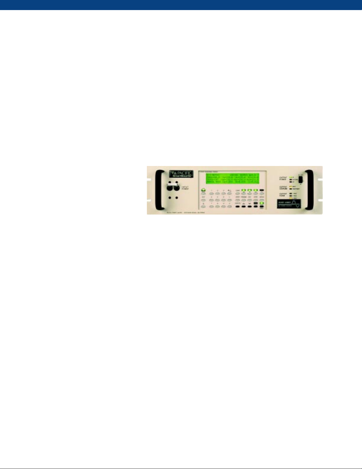
The AMX Series is a family of High Performance Linear AC power sources covering the power range from 500 VA to 12
kVA. The product line offers both single and three phase models. Units are conservatively designed and output power
ratings are based on the most severe combination of input line, output voltage, power factor, and temperature. This approach
to product design allows the AMX Series to excel when delivering the high peak load currents demanded in the AC test
environment. Great emphasis has been placed on low acoustic noise, ease of installation, and maximum power per cubic
inch of rack space. Control and operating features provide a high degree of application versatility and ease of use for the test
engineer. Applications range from simple, manually controlled frequency conversion to harmonic testing and sophisticated
bus programmable transient simulation.
An exceptionally broad bandwidth (50 kHz
small signal) combined with peak/RMS
current of 4-6:1 give the AMX Series the
ability to produce high quality, low
distortion output power into the most
dynamic loads.
Pacific Model 308AMX with UPC Controller
KEY FEATURES PROVIDE APPLICATION VERSATILITY
• IEEE-488.2 or RS-232C with SCPI compatibility
• LabVIEW for Windows®/LabWindows® drivers
• Waveform Creation by Harmonic Synthesis
• Graphical Analysis (Voltage and Current)
• Harmonic Analysis (Voltage and Current)
• Metering of RMS and Peak Values
• Continuous Self Calibration (CSC)
• Line Sync Option
• 6:1 Peak Current Capability
• Low Impedance for IEC555 Testing
• Programmable Output Impedance
• Up to 0-300 VAC Direct Coupled Out
• 1 Phase / 3 Phase Switch Selectable
• 20-5000 Hz Full Power Bandwidth
• Power Levels from 500 VA to 12 kVA
• Externally Referenced Meter Calibration
• CE and ETL Mark available
DESIGN PROVIDES TOTAL CONTROL OF AC POWER
• All AMX Series power source models may be equipped with either a digitally programmable Oscillator/Controller (UPC
type) or a manually controlled Oscillator (UMC type).
• Single phase power source models may be controlled to operate on either a 0-135 VAC range or a
0-270 VAC range. Three phase models are additionally switchable to 3ø/1ø output power form.
• Total control of the output power form and the selection of either the direct output or the optional transformer output is
available from the front panel or the bus.
• All operating functions may be controlled from either the front panel or from a remote RS-232 or IEEE 488.2/ SCPI
BUS. LabVIEW for Windows® and LabWindows® Instrument Drivers are available.
2
Page 3
SPECIAL AMX SERIES OPERATING FEATURES
CONTINUOUS SELF CALIBRATION
Provides for exceptional accuracy of the AC output Voltage. When enabled, accuracy improves to ±0.03% referenced to the power
source internal voltmeter.
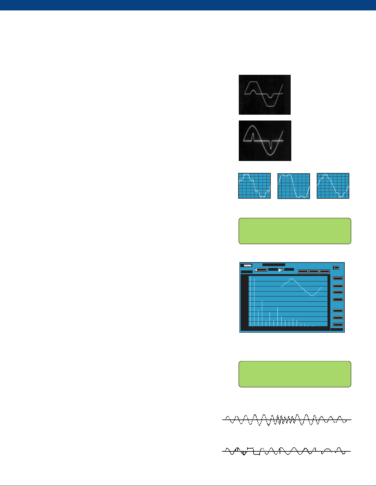
PROGRAMMABLE D YN AMIC OUTPUT
IMPEDANCE (OPTIONAL)
Provides positive or nega ti v e output impedance. T he output v oltage wa v eform at
the right is flattened as a result of a high peak load current drawn by an electronic
load at the peak of the sinewave .
Engaging the dynamic output impedance (Zº) feature dynamically compensates,
as shown at the right, for the distribution or transformer losses up to ±10% of the
output voltage.
WAVEFORM LIBRARY
Up to 99 different waveforms ma y be stored in the wa v eform library f or e x ecution
as part of a steady state test program or for substitution in any output phase as part
of a transient test program. Memory location #1 is a non-editable high resolution
sine wave. Locations 2-16 are editable and may be substituted in any output
phase. Locations 19-99 are factory stored, non editable waveforms that may be
copied to 2-16 for edit and execute.
THD=8.7%
EDIT WAVEFORM: NUMBER=16 RANGE=2-22
STARTING PHASE ANGLE=0 0-359.5°
ENDING PHASE ANGLE=0 0-359.5°
VOLTAGE IN PERCENT=-100 (+/-)0-100%
Oscillograph of voltage
and current waveform at
load due to distribution
losses. THD=6.6%
Same conditions with
programmable Zo
engaged. THD=0.25%
THD=22.2%
THD=18.1%
WAVEFORM EDIT
Provides the ability to modify a stored wav eform by specifying the waveform
amplitude desired at each specific phase angle. This method can be used to
quickly create spikes, dropouts, notches and other sub-cycle wav e conditions. The
resulting modified waveform can be stored for e x ecution.
W AVEFORM ANAL YSIS (OPTIONAL)
Provides both a graphic and numeric display of the harmonic structure of a
voltage or current waveform. The w a v eform is sampled at 512 samples per cycle
using a 12 bit A/D converter. The resulting high f idelity w a v eform is analyzed for
its harmonic structure up through the 51st harmonic. Data presented includes
the magnitude of each harmonic in %, the total harmonic distortion, and the odd
and even harmonic distortion in %.
WAVEFORM SYNTHESIS (OPTIONAL)
Provides the ability to quickly create virtually any AC T est Wav eform that may be
required by building it out of harmonics. The process is as simple as ke ying in the
harmonic multiple, the amplitude, and the phase angle for each desired harmonic
up through the 51st. If desired, waveforms may also be created in the time domain
by making entries from the front panel or by downloading from a host PC.
TIME BASED TRANSIENTS
Provide the ability to create and execute on command, transients that
occur linearly over a specified time segment to modify output voltage or
frequency .
WAVEFORM EDIT
024
SELECT ITEM TO GRAPH
CURRENT VOLTAGE
PHASE A
WAVEFORM UNDER ANALYSIS
6
8
10 12 14 16 18 20 22 24 26 28 30 32 34 36 38 41
% THD
12.9
HARMONIC CONTENT OF
% OHD
12.9
% EHD
0.6
0.
%CONTENT
10.0
9.0
8.0
7.0
6.0
5.0
4.0
3.0
2.0
1.0
0.0
HARMONIC CONTENT OF
WAVEFORM SYNTHESIS: WAVEFORM #2
HARMONIC: 2nd 3rd 4th 5th 6th
CONTENT: .1% 0% 0% 0% 0%
ØANGLE: 0° 0° 0° 0° 0°
WaAVEFORM SYNTHESIS
GPIB address
1
FREQ
400.00
Vrms
115.6
Irms
115.6
Ipeak
0.00
KW
0.0000
KVA
0.0000
PF
1.0
HARMONIC#
CYCLE BASED TRANSIENTS
Provide the ability to create and execute, on command, transients that
substitute a selected waveform in the output for 1 to 100 cycles. T he
waveform being substituted can be selected and/or modif ied from the
waveform library. Substitution is for an integer number of cycles,
regardless of frequency.
3
TIME BASED TRANSIENTS
CYCLE BASED TRANSIENTS
Page 4

METERING WAVEFORM CONTROL/ANALYSIS
V/I METER: ENTRY: 120.0
FREQ=60.00 Va=120.0 Vb=120.0 Vc=120.0
SENSE=INT Vab=208.0 Vbc=208.0 Vca=208.0
MANUAL MODE Ia=06.00 Ib=06.22 Ic=06.15
POWER METER: PHASE A PHASE B PHASE C
KVA 0.720 0.746 0.738
KW 0.720 0.746 0.738
PF 1.000 1.000 1.000
AMPS METER: PHASE A PHASE B PHASE C
RMS 0.720 0.746 0.738
PEAK 1.044 1.119 1.383
CREST FACTOR 1.45 1.50 1.90
EDIT WAVEFORM: NUMBER=16 RANGE=2-22
STARTING PHASE ANGLE=0 0-359.5°
ENDING PHASE ANGLE=0 0-359.5°
VOLTAGE IN PERCENT=-100 (+/-)0-100%
WAVEFORM SYNTHESIS: WAVEFORM #2
HARMONIC: 2nd 3rd 4th 5th 6th
CONTENT: .1% 0% 0% 0% 0%
ØANGLE: 0° 0° 0° 0° 0°
ØA CURRENT THD=17.8 % OHD=17.8EHD=0.3%
HARMONIC: 2nd 3rd 4th 5th 6th
CONTENT: .1% 17.8% 0% 0% 0%
ØANGLE: 0° 0° 0° 0° 0°
FUNCTION KEY
PROVIDES ACCESS TO SPECIAL FUNCTIONS
SETUP: PRESS 1 FOR PROGRAM SETUP
2 FOR WAVEFORM SETUP
3 FOR GENERAL SETUP
4 FOR CALIBRATION MENU
PROGRAM SETUP
• Copy a program
• Delete a program
• Erase all memory,
reset CPU
WAVEFORM SETUP
• Edit a waveform
• Copy a waveform
• Waveform synthesis
GENERAL SETUP
• UPC setup
• LCD setup
• UPC status
• Power source status
• Range control
• Slew rate setup
CALIBRATION MENU
• Execute externally
referenced calibration
• View calibration
constants
4
SPECIAL FUNCTIONS ACCESSED
THROUGH UPC SETUP MENU
• SENSE Establishes either local or external
sense for metering and CSC.
• CSC Continuous Self Calibration –
provides for exceptional voltage
accuracy.
• PROGRAM Programmable output impedance
° dynamically compensates for
Z
output transformer or line
distribution losses. Can simulate a
soft power grid.
• TRANSITION Permits control of the transition
TIME time when changing the output
voltage and frequency.
• FREQUENCY Sets min and max programmable
LIMITS frequency limits.
• VOLT AGE Sets min and max programmable
LIMITS voltage limits.
Page 5
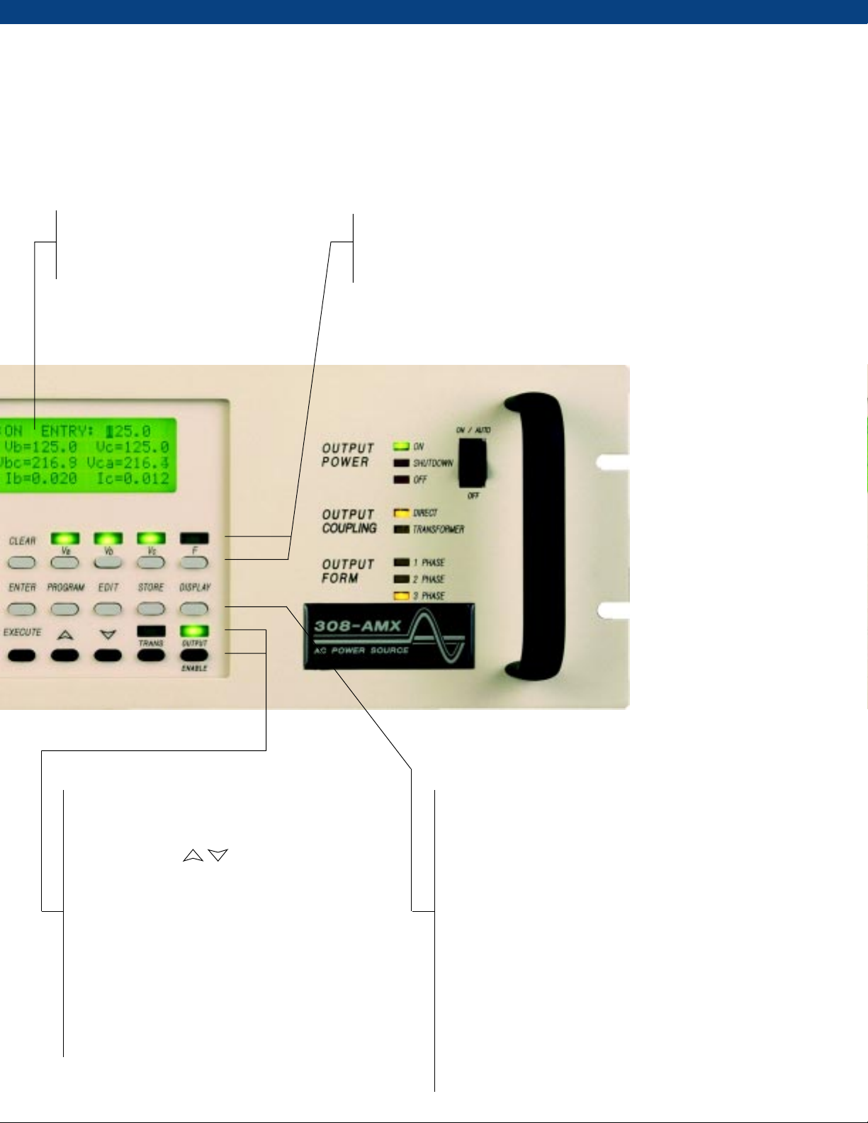
TOTAL CONTROL, METERING,
AND ANALYSIS OF AC PO WER.
SIMPLE INTUITIVE OPERATION.
INFORMATIVE 160 CHARACTER
LCD DISPLAY
• Soft green backlight
• Adjustable
PARAMETER SELECT KEYS
Select phase voltages and operating frequency when manual control
is desired. The selected parameter is indicated by the LCD display.
The clear key erases entries and keeps erasing with repeated pressing
until the basic VI screen is displayed.
EXECUTE KEY
Instantly executes a stored program that has been
selected with the program key.
SLEW KEYS
Smoothly change the designated voltage or
frequency parameters. Rates are separately
programmable.
TRANSIENT (TRANS) KEY
Turns time based or cycle based transients On or
Off. Indicator is On when transient is executed.
OUTPUT ENABLE KEY
Turns the output contactor of the power source On
or Off. Indicator is On when the contactor is closed.
ENTER KEY
Stores new parameter data that has been keyed in.
PROGRAM KEY
Selects 1 of 99 programs for edit or execution.
EDIT KEY
Selects the program edit mode and prompts for new
entry.
STORE KEY
Stores a program upon completion of editing.
DISPLAY KEY
Sequences through each metering screen:
• VI Meter
• Power Meter
• AMPS Meter
• W a vef orm Analysis (option)
5
Page 6

AMX POWER SOURCE MODELS
MODEL
105AMX
108AMX
112AMX
125AMX
140AMX
305AMX
308AMX
312AMX
318AMX
320AMX
330AMX
345AMX
360AMX
390AMX
3120AMX
RATED
P0WER
(VA)
500
750
1200
2500
4000
500
750
1200
1800 3Ø
2000
3000
4500
6000
9000
12000
OUTPUT
VOLTS MAX
(Note 2)
)
(V
RMS
1Ø 135/270 4/2 40/20
1Ø
1Ø
1Ø
1Ø
3Ø
3Ø
3Ø
3Ø
3Ø
3Ø
3Ø
3Ø
3Ø
OUTPUT
FORM
(Note 1)
135/270
150/300
150/300
135/270
135/270
135 L-N
135/270
135 L-N
150/300
150 L-N
135/270
135 L-N
135/270
135 L-N
135/270
135 L-N
135/270
135 L-N
135/270
135 L-N
135/270
135 L-N
135/270
135 L-N
OUTPUT
AMPS
(A
)
RMS
(Note 3)
6/3 40/20
10/5
20/10
32/16
4/2
1.5/Ø
6/2
2/Ø
10/3.3
3.3/Ø
15/5
5/Ø
18/6
6/Ø
24/12
8/Ø
36/12
12/Ø
48/16
16/Ø
72/24
24/Ø
96/32
32/Ø
OUTPUT
150/50
330/110
110/Ø
420/140
140/Ø
AMPS
(APK)
40/20
90/45
140/70
45/15
15/Ø
45/15
15/Ø
45/15
15/Ø
60/20
20/Ø
60/20
20/Ø
50/Ø
165/55
55/Ø
210/70
70/Ø
INPUT
POWER
FORM
(Note 4)
1Ø
1Ø
1Ø
3Ø
3Ø
1Ø
1Ø
1Ø
3Ø
3Ø
3Ø
3Ø
3Ø
3Ø
3Ø
PANEL
HEIGHT
(IN.)
5 1/4 65
5 1/4
5 1/4
10 1/2
14
5 1/4
5 1/4
5 1/4
8 3/4 100
8 3/4
14
14
14
28
2 each x 14
28
2 each x 14
WEIGHT
(LBS.)
65
65
110
170
65
65
70
100
162
177
185
175 x 2
185 x 2
Notes:
1. All single phase units are operable with dual voltage ranges as listed. All three phase units are operable as single phase with dual voltage range capability or as three phase.
Output voltage ranges and 1f / 3f conversions are selected by front panel or bus command.
2. Output voltage ranges listed are for standard units. VMAX is achievable with nominal input voltage at full load. Other voltage ranges are
available with the output magnetics option.
3. Current ratings at 125 VRMS output.
4. Input power frequency is 47-63 Hz. Single Phase: 100, 110, 120, 200, 208, 220, 230, 240, VAC ± 10%. Three phase: 208, 220, 240, 380, 416 VAC ± 10%.
POWER SOURCE SPECIFICATIONS
Output Frequency: 20 to 5000 Hz. Full Power
Line Regulation: 0.1% max for a 10% line change
Load Regulation: 0.25% 20 to 2000 Hz.
0.5% 2000 to 5000 Hz.
Can be improved to less than 0.03%
with CSC engaged.
Output Distortion: 0.1% THD from 20 to 1000 Hz
0.25% THD from 1000 to 5000 Hz
Ripple and Noise: -72 dB
Response Time: 5µsec. typical to a step load change. Small
MECHANICAL SPECIFICATIONS
All models are designed for operation in 19 inch equipment racks.
Models above 1800 VA have side handles for ease of handling.
Mounting: Standard 19 inch rack. Slide rails are available
as an option for all models.
Height: See model table above for panel height.
Depth: Will not exceed 24 inches from the front panel
to the rear of the chassis, including
connectors, handles and cabling.
Cooling: Forced air, front or side intakes, rear exhaust
with auto fan speed control for low acoustic
noise operation.
signal band-width is 5 Hz. to 50 kHz, typical.
POWER SOURCE SPECIFICATIONS
AMX Series Power sources can be equipped with output transformers to provide an alternate output voltage range. Selection of direct or transformer coupled range is performed by the controller via front panel or bus command. The standard
frequency range for transformer coupled outputs is 45 to 5000 Hz. Standard output ratios are 1.5:1, 2.0:1, and 2.5:1.
Transformer outputs are supplied internally or externally via a Magnetics Module. Consult the factory f or additional
information regarding special output ranges not listed.
6
Page 7

UPC CONTR OLLER SPECIFICATIONS
The UPC controller is essentially a 3f AC arbitrary waveform generator and Precision AC metering system. Each
waveform stored in the UPC is encoded with 12 bit amplitude and 10 bit time resolution for each cycle . The waveform for
each phase may be independently selected and may be independently
varied in amplitude and phase angle with respect to phase A.
The UPC output metering samples the output volts and amps at 512 samples per measurement using a 12 bit A/D converter.
This technique provides exceptional metering accuracy and resolution (20 bits), and delivers a high-fidelity waveform back
to a host computer for analysis.
The UPC includes a remote GPIB interface compatible with IEEE 488.2 and SCPI. An available option is an RS-232 serial
port that operates up to 38.4 kBaud.
Frequency: 20.00 to 5000 Hz ±0.01%
Voltage: Programmable, 0-VMAX, in 0.1 volt steps
Direct (see table on page 6)
Voltage: Multi-range units are equipped with
Transformer output transformers. When alternate range is
selected, voltage at transformer output is
programmable in steps of 0.5 volts.
Accuracy: Executive voltage is within ±50 mv (0.03%)
Command of command voltage, referenced to the
Voltage internal voltmeter with CSC engaged.
Accuracy: ± 0.01%, 20-5000 Hz
Output Zo: Dynamic output impedance (Zo) is
(Optional) programmable, 0 to ± Zo max. in 0.1%
steps. Zo value in milliohms varies with
different models but usually results in a ±
10% change in output voltage at maximum
load amps.
Phase: Phase Angle (f) of Phases B and C
Angle relative to Phase A is programmable from 0-
359° in 1° increments ± 0.5°.
Voltmeter: Range - 0-354 volts L-N
0-708 volts L-L
Resolution - 0.10VAC to front panel
0.001VAC to remote interface
Accuracy - ± 0.25% of reading ± 0.1% of
range (50-500Hz)
Ammeter: Range - 300% of system current rating
Resolution - 0.01AAC to front panel
0.001AAC to remote interface
Accuracy - ± 0.25% of reading ± 0.1% of
range (50-500Hz)
Power Meter: Range - Based on ammeter range
Resolution - 1.0 watts or VA to front panel
0.001 Watts or VA to remote
interface
Accuracy - ± 1% of Full Scale
Power Factor: Calculated and displayed to three significant
& Crest Factor digits.
Ext. Input: Each phase is algebraically summed with
UPC waveform and amplified 25X to the
direct output.
Current: Current limit is programmable from 0
Limit to Ipeak maximum of the power source.
Accuracy is ± 1%, resolution ± 0.05%.
Library: Stores up to 99 steady state parameter
Steady sets consisting of waveform, voltage,
State frequency, f angle and current limit. Can be
Programs executed by program number from the front
panel or the bus.
Library: Stores up to 99 transient programs - one
Transient associated with each steady state program.
Programs Allows for changes in v olts and frequency
vs. time, or waveform changes by c ycle count.
Library: Stores up to 99 waveforms that can be edited
Waveform and executed in any manner and in any
output phase.
Amplitude: ±10 volt input for each phase
Mod. Input modulates the output ± 100%
Sync Outputs:1) Zero crossing, Phase A
2) Transient start-stop
3) True when Transient is enabled
4) Clock - 1024 times the output freq.
Command: Average time to start of parameter change
Response from bus command (end of string character)
Time is 50 ms. Ramp transition time to final value
is settable from 250 µs to 300 sec.
Waveform : Permits waveform creation by entering %
Synthesis amplitude and phase angle for the 2nd
through the 51st harmonics.
Waveform: Reports voltage and current waveform
Analysis harmonic content in % and phase angle
for the 2nd through the 51st harmonics.
Displays THD, OHD, EHD in %.
7
Page 8
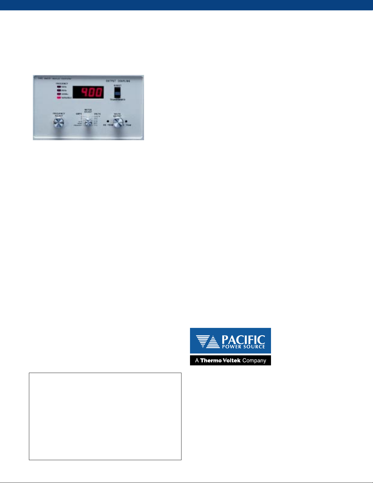
MANUAL CONTROL OF A C POWER
Provide easy manual control with Pacific’s UMC-31 Manual AC Power Controller.
• Obtain precision frequency and phase conversion
for manufacturing and test.
• Provide high quality, general purpose lab power where
test versatility is required.
• Achieve low cost and power form flexibility for
power supply tests.
SPECIFICATIONS UMC-31 CONTROLLER
UMC-31 Manual Controller
The UMC-31 provides operational control
and high quality oscillator signals for both
single and three phase Power Sources.
Phase: Select single, split, or three phase operation by
internal jumper. Phase angles are fixed at 120° and
240° for three phase operation.
Frequency: Select 50, 60, or 400 Hz fixed or a variable
frequency mode of 45 to 500 Hz.
Voltage: 0-VMAX via 10 turn potentiometer on the front panel.
Metering: Autoranging Volts, Amps, and Frequency.
For additional data sheets or technical application
assistance, please call or fax Pacific
Power Source, attn.: Sales Department.
Authorized Representative
Pacific Power Source
15122 Bolsa Chica Street
Huntington Beach, CA 92649 USA
Tel: +1 714 898 2691
+1 800 854 2433
Fax: +1 714 898 8076
http://www.pacificpower.com
A Division of Thermo Voltek, a Thermo Electron Company
Thermo Voltek
©Thermo Voltek Corporation. Specifications subject to change without notice.
8
 Loading...