

Page 1
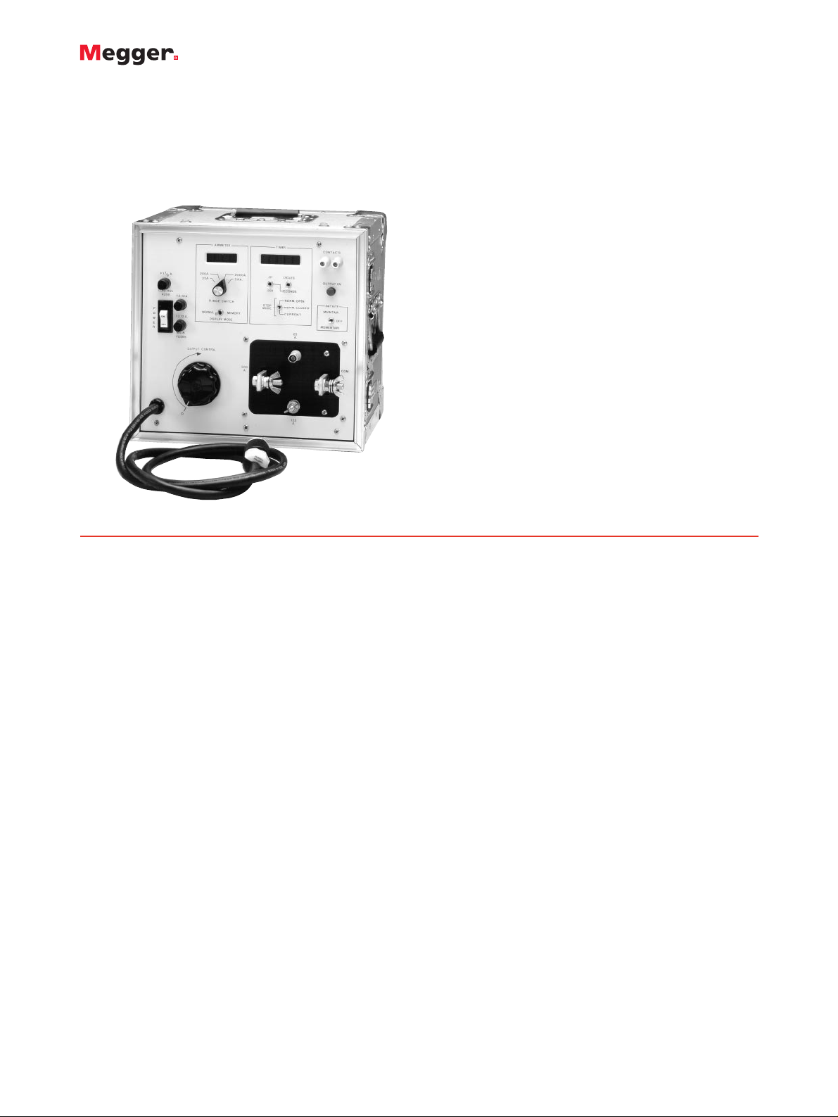
CB-832
Circuit Breaker and Overload Relay Test Set
■
Digital memory ammeter
■
Digital multirange timer
■
High-current output
■
Solid-state output initiate circuit
CB-832
Circuit Breaker and Overload Relay Test Set
DESCRIPTION
The CB-832 test se is a high-current circuit breaker and
overload relay test set. Model CB-832 is designed to test
the circuit breaker and overload relays by means of
primary current injection.
The CB-832 is a self-contained test set that incorporates a
variable high-current output and appropriate control
circuitry and instrumentation for testing thermal, magnetic
or solid-state motor overload relays; molded-case circuit
breakers; and ground-fault trip devices.
APPLICATIONS
One of the most common applications of the CB-832 is the
calibration of magnetic overload relays, such as those
used for protecting air conditioning systems. By providing
up to 1000 amperes to simulate overload conditions, it also
is capable of testing the time-delay characteristic of
magnetic overload relays rated up to 500 amperes.
In addition, the CB-832 can test the time-delay
characteristics of thermal motor overload relays and
molded-case circuit breakers rated up to 225 amperes,
when following the recommended test procedure of
testing the time delay of thermal devices at three times
their rating.
Higher currents are available for the short durations
required to test an instantaneous trip element. For
example, the test set will provide a short-duration output
of 1800 amperes through a typical 225 ampere, moldedcase circuit breaker. Additional applications include
verifying the ratio of current transformers and testing
panelboard ammeters and voltmeters.
FEATURES AND BENEFITS
■
Digital memory ammeter: High-accuracy, directreading instrumenthas read-and-hold memory for
measurement of short-duration currents.
■
Digital multirange timer: Crystal-controlled, highaccuracy instrument measures operating time to 1
millisecond.
■
High output current: Provides instantaneous currents
up to 1800 amperes through a 225-ampere breaker.
■
Solid-state output initiate circuit: Solid-state circuit
eliminates the need for contact maintenance.
■
Protection: Overload and short-circuit protection is
incorporated.
■
Enclosure: Heavy-duty Formica enclosure is equipped
with carrying handles and removable hinged cover that
protects instruments and controls during transportation
and storage. Space is provided for test lead storage.
SPECIFICATIONS
Input (specify one)
120 V OR 240 V, 50/60 Hz, 1f
Output
Output Ranges: Continuously adjustable in three ranges to meet
a variety of test circuit impedances:
0 to 500 A at 3.5 V max.
0 to 125 A at 14 V max.
0 to 25 A at 70 V max.
Page 2

CB-832
Circuit Breaker and Overload Relay Test Set
Output Capacity: The output circuit is designed to provide shortduration overloads.
The output ranges will provide several times their current rating,
provided the output voltage is sufficient to push the desired
current through the impedance of the test circuit.
The test set is capable of testing the time-delay characteristics of
magnetic overload relays rated to 500 A using a test current of
two times their rating (1000 A).
avoid damage or overheating of the device under test while
setting the test current.
In the maintained mode, the output remains energized until
manually turned off or, when performing timing tests, until the
device under test operates—this both stops the timer and deenergizes the output.
INSTRUMENTATION
Ammeter
To measure the output current, the test set incorporates a solidstate digital instrument with multiple ranges and a read-and-hold
memory to measure short-duration currents.
Operating Modes (switch-selected)
Memory
Normal
Digital Display
3
1
/
2
digit, extra-bright LED display with 0.3-in. (7.62 mm) numerals
Ranges (switch-selected)
0 to 19.99/199.9/1999 A/3.00 kA
Continuous Accuracy (overall ammeter system)
±1% of reading, ±1 digit on three high ranges, ±1 digit on low
range ±1% of range
Timer
A solid-state digital timer is incorporated to measure the elapsed
time of the test in either seconds or cycles.
It uses a crystal-controlled oscillator, therefore, its accuracy is
independent of the line frequency.
Display: 5-digit, extra-bright LED display with 0.3 in. (7.62 mm)
numerals
Ranges (switch-selected)
0 to 99.999 s
0 to 999.99 s
0 to 99999 cycles
Accuracy
±0.005% of reading, ±1 digit
Timer Control Circuit
This circuit automatically starts the timer when the output is
energized and automatically stops the timer and de-energizes the
output when the device under test operates.
This circuit accommodates the following test conditions by simple
switch selection of the appropriate mode:
Current Actuated: Used to test a device that has no auxiliary
contacts to monitor, such as a single-pole circuit breaker. The
timer stops when the output current is interrupted.
Normally Closed: Used to test a device with normally closed
contacts. The timer stops and the output is de-energized when the
contacts open.
Normally Open: Used to test a device with normally open
contacts. The timer stops and the output is de-energized when the
contacts close.
Dimensions
14 H x 14.5 W x 13.4 D in.
(356 H x 368 W x 343 D mm)
Weight
75 lb (34.1 kg)
Item (Qty) Cat. No.
Model CB-832
120 volt input CB-832-115
230 volt input CB-832-230
Included Accessories
Timer leads, 5 ft (1.5 m) [1 set] 1282
Lead bag [1] 684008
Current leads
No. 6, 5 ft (1.5 m) [1 set] 16295
4/0, 4 ft (1.2 m) [1 set] 9311
Fuses
12 A, 250 V, MDA [5] 9312
0.125 A, 250 V, MDL [5] 981
Instruction manual [1] 9841
ORDERING INFORMATION
Overload Capability
Percent Maximum Maximum
Rated Time Time
Current On Off
100 (1x) 30 min 30 min
200 (2x) 3 min 8 min
300 (3x) 30 s 4 min
400 (4x) 7 s 2 min
It will test the time-delay characteristic of thermal devices rated up
to 225 A using the recommended test current of three times their
rating (675 A).
Also, to perform an instantaneous trip test, it will provide 1800 A
through a typical 225-ampere, molded-case circuit breaker.
Overload Capability: To increase use of the test set, it is designed
so that the current ratings may be exceeded for short durations.
Because the magnitude of the output current is determined by the
impedance of the load circuit, the voltage rating must be sufficient
to push the desired current through the device under test and the
connecting test leads.
Output Initiate Circuit: The test set uses a solid-state output
initiating circuit. To increase reliability and eliminate contact
maintenance, this circuit uses a triac instead of a contactor to
initiate the output.
Output Initiate Control Circuit: The initiating control circuit
provides momentary and maintained modes to control output
duration.
The momentary mode is used whenever the output is to be for a
short duration. An example is an instantaneous trip test, or to
UK
Archcliffe Road Dover
CT17 9EN England
T +44 (0) 1304 502101
F +44 (0) 1304 207342
UNITED STATES
4271 Bronze Way
Dallas TX75237-1088 USA
T 800 723 2861 (USA only)
T +1 214 330 3203
F +1 214 337 3038
OTHER TECHNICAL SALES OFFICES
Valley Forge USA, Toronto CANADA,
Mumbai INDIA, Trappes FRANCE,
Sydney AUSTRALIA, Madrid SPAIN
and the Kingdom of BAHRAIN.
Registered to ISO 9001:2000 Reg no. Q 09290
Registered to ISO 14001 Reg no. EMS 61597
CB832_DS_en_V10
www.megger.com
Megger is a registered trademark
 Loading...