

Page 1
2 5 0 7 W a r r e n S t re et, El kh ar t, I N 4 6 5 1 6 U S A | 5 7 4 . 2 9 5 . 9 4 9 5 | w w w . A E T e c h ro n . co m
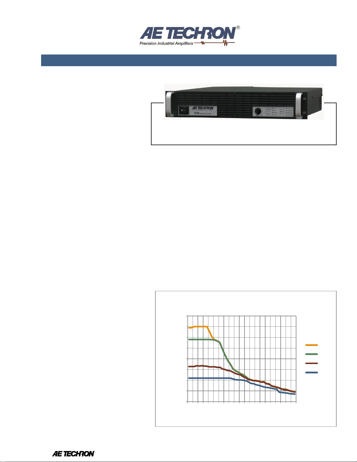
7224 SPECIFICATION SHEET
0
20
40
60
80
100
120
140
160
0 30 70 110 150 190 230 270 310 350 390
Volts Peak
Frequency in kHz
Voltage Potential vs. Frequency
8 ohm
4 ohm
2 ohm
1 ohm
Features
Frequency bandwidth of DC to 300 kHz at rated power.
Continuous output of over 1,100 watts RMS at 4 ohms.
40 mSec pulses of up to 52 amperes peak into a 0.5 ohm load.
System output of over 4,000 watts or over 200 amperes
maximum is possible with multiple, interconnected amplifiers.
Efficient design and light weight chassis materials allow
amplifier to occupy only 2U height and weigh only 41 lbs.
Protection circuitry protects the AE Techron 7224 from input
overloads, improper output connection (including shorted and
improper loads), over-temperature, over-current, and supply
voltages that are too high or low.
7224 with “P” option offers precision control of output offset, DC
drift and gain linearity.
Shipped ready to operate from 120-volt (±10%) single-phase
AC mains; 220/240-volt model available on request.
The AE Techron 7224 amplifier is a 1
kVA, DC-enabled unit that provides
exceptional versatility and value. It
features DC to 300 kHz bandwidth and
offers a wide range of fieldconfigurable options. A single 7224
can output a 40 mSec pulse with up to
52 amperes peak current. In
continuous operation, a 7224 can
provide 1,100 watts RMS of output
power. If more current or power is
needed, up to four amplifiers can be
combined in series or parallel and
operate as a single system.
The 7224 can operate in either voltage
or current mode and can be
configured by the customer for highvoltage/low-current, medium voltage
and current, or low-voltage/highcurrent applications. It provides very
low noise and fast slew rates, and can
safely drive a wide range of resistive,
inductive loads.
The 7224 is typically used to create
waveforms found in EMC standards
like CS2009, DO-160, MIL STD 461,
and as a gradient amplifier for very
small bore, high-gain MRI and NMR
systems.
Performance
Testing was done at 100 Hz.
Continuous DC power levels are
lower. See DC Specifications chart.
7224P accuracy was measured when
driven into a 10-ohm load with
between 0.1VDC and 6VDC or
between 0.2VAC and 5VAC presented
at its inputs.
Small Signal Frequency Response:
DC - 300 kHz +0.0 to -1.0 dB
7224 Datasheet Information subject to change. 1/28/2013
Page 2
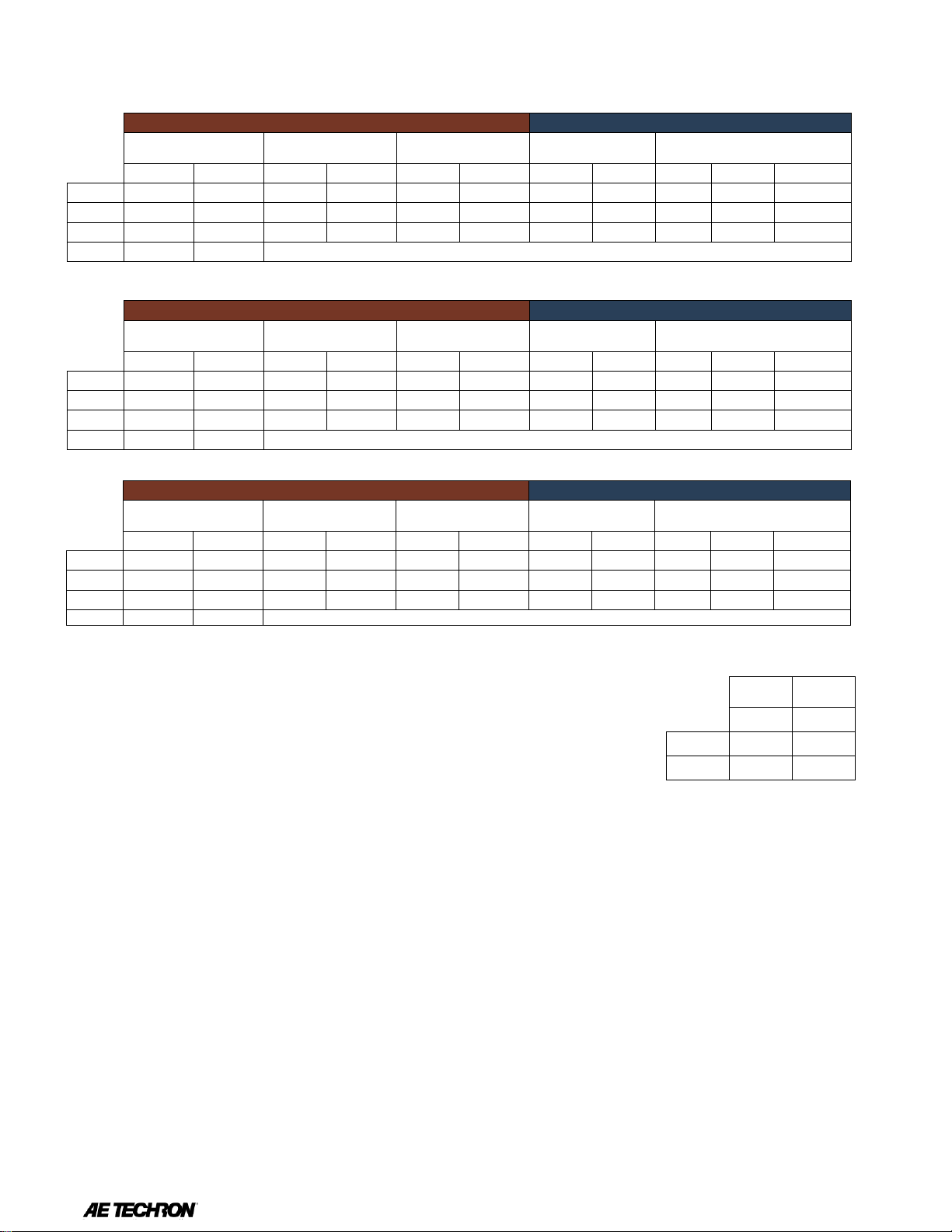
DC Specifications
Low Voltage
High Current
5 Min
1 Hr
Volts DC
Amps DC
Amps DC
24.0
26
20
13.5
20
16
AC Specifications - High Voltage Mode
PEAK OUTPUT
RMS OUTPUT
40mSec Pulse,
20% Duty Cycle
5 Minute,
100% Duty Cycle
1 Hour,
100% Duty Cycle
5 Minute,
100% Duty Cycle
1 Hour,
100% Duty Cycle
Ohms
Volts
Amps
Volts
Amps
Volts
Amps
Volts
Amps
Volts
Amps
Watts
16
158
10
158
10
158
10
112 7 112 7 774 8 154
19
136
16
136
16
96
12
96
12
1108 4 124
31
108
26
61
15
76
18
43
10
442 2 98
49
AC Specifications - Mid-Level Mode
PEAK OUTPUT
RMS OUTPUT
40mSec Pulse,
20% Duty Cycle
5 Minute,
100% Duty Cycle
1 Hour,
100% Duty Cycle
5 Minute,
100% Duty Cycle
1 Hour,
100% Duty Cycle
Ohms
Volts
Amps
Volts
Amps
Volts
Amps
Volts
Amps
Volts
Amps
Watts 4 72
18
69
16
69
16
49
12
49
12
566 2 61
30
57
26
57
26
40
19
40
19
746 1 47
47
43
40
21
21
30
28
15
15
220
0.5
26
52
AC Specifications - High Current Mode
PEAK OUTPUT
RMS OUTPUT
40mSec Pulse,
20% Duty Cycle
5 Minute,
100% Duty Cycle
1 Hour,
100% Duty Cycle
5 Minute,
100% Duty Cycle
1 Hour,
100% Duty Cycle
Ohms
Volts
Amps
Volts
Amps
Volts
Amps
Volts
Amps
Volts
Amps
Watts 1 29
29
29
29
21
21
21
21
420
0.75
26
34
26
34
18
24
18
24
442
0.5
23
45
23
45
16
32
16
32
511
0.25
8-Ohm Power Response:
± 140 Vpk DC to 60 kHz
± 50 Vpk DC to 180 kHz
± 30 Vpk DC to 300 kHz
Slew Rate:
75 V/µSec
Residual Noise:
10 Hz to 300 kHz: 950 µV (0.95 mV)
10 Hz to 80 kHz: 300 µV (0.3 mV)
Signal-to-Noise Ratio:
10 Hz - 30 kHz: –113 dB
10 Hz - 80 kHz: –106.6 dB
10 Hz - 300 kHz: –99.9 dB
Unit to Unit Phase Error:
± 0.1 degrees at 60 Hz
THD:
DC - 30 kHz less than 0.1%
Output Offset:
7724: Less than ±5 mV
7224P: Less than ±400 µV
DC Drift:
7224: <±1.5 mV
7224P: <±200 µV
(after 20 minutes of operation)
Output Impedance:
28 mOhm in Series with 1 µH
Phase Response:
± 5 degrees (10 Hz - 10 kHz) plus 560 nsec propagation delay
Input Characteristics
Balanced with ground:
Three terminal barrier block connector 20 k ohm differential
Unbalanced:
BNC connector, 10k ohm single ended. Fixed or variable gain
Gain:
Voltage Mode: 20 volts/volt
Current Mode: 5 amperes/volt
Gain Linearity (over input signal, from 0.2V to 5V):
7224: 0.15%
7224P: 0.02% (DC); 0.05% (AC)
Max Input Voltage:
± 10 V balanced or unbalanced
7224 Datasheet Information subject to change. 1/28/2013
Page 3

-3
-2
-1
0
1
0 30 70 110 150 190 230 270 310 350
dB
Frequency in kHz
Frequency Response
8 ohm 1
watt
10.0
15.0
20.0
25.0
0 5 10 15 20 25 30 35 40 45 50 55 60
DC Current
Time in Minutes
Current Over Time
at 13.5VDC
Common Mode Rejection:
-58 dB with 5 V input
Display, Control, Status, I/O
Front Panel LED Displays indicate:
Ready, Standby, Fault, Over Temp,
Over Voltage, Overload
Soft Touch Switches for:
Run, Stop, Reset
Gain Control, when enabled:
Voltage gain adjustable from 20 to 0
On/Off Breaker
Back Panel Power Connection:
25 Amp IEC (with retention latch)
Signal Output:
+/Common/Sampled Common
Signal Input:
User Selectable BNC or Barrier Strip
Balanced
Communication Capabilities
Current Monitor: ± 1 V / 5 A ± 1%
Voltage Monitor: ± 1 V / 1 V ± 1%
Reporting:
System Fault, Over Temp, Over
Voltage, Over Load
Control:
Force to Standby, Reset after a fault
Multiple Unit Configuration
Series Operation:
Total Voltage (1, 2, 3, or 4-7224’s):
150 Vpk, 300 Vpk, 450 Vpk or 600 Vpk;
Increased slew rate up to 200 V/µSec
Parallel Operation:
Total Current (1, 2, 3, or 4-7224’s):
50 Apk, 100 Apk, 150 Apk or 200 A
7224 Datasheet Information subject to change. 1/28/2013
pk
Page 4

Two 7224s in Series
High Voltage
Low Current
5 Min, 30% duty Cycle
1 Hr, 100% duty Cycle
Ohms
Volts Peak
Amps Peak
Volts Peak
Amps Peak
32
316
9.8
316
9.8
16
272
16.3
272
16.3 8 216
25.7
122
14.5
Medium Voltage
Medium Current
5 Min, 30% duty Cycle
1 Hr, 100% duty Cycle
Ohms
Volts Peak
Amps Peak
Volts Peak
Amps Peak 8 138
16.4
138
16.4 4 114
26.2
114
26.2 2 86
39.6
42
21
Low Voltage
High Current
5 Min, 30% duty Cycle
1 Hr, 100% duty Cycle
Ohms
Volts Peak
Amps Peak
Volts Peak
Amps Peak 2 58
29
58
29
1.5
52
34
52
34 1 45.4
45
45.4
45
Two 7224s in Parallel
High Voltage
Low Current
5 Min, 30% duty Cycle
1 Hr, 100% duty Cycle
Ohms
Volts Peak
Amps Peak
Volts Peak
Amps Peak 8 158
19.6
158
19.6 4 136
16.3
136
16.3 2 108
25.7
61
14.5
Medium Voltage
Medium Current
5 Min, 30% duty Cycle
1 Hr, 100% duty Cycle
Ohms
Volts Peak
Amps Peak
Volts Peak
Amps Peak 2 69
32.8
69
32.8 1 57
54.2
57
52.4
0.5
43
79.2
21
42
Low Voltage
High Current
5 Min, 30% duty Cycle
1 Hr, 100% duty Cycle
Ohms
Volts Peak
Amps Peak
Volts Peak
Amps Peak
0.5
29
58
29
58
0.375
26
68
26
68
0.25
22.7
90
22.7
90
AE Techron Sales Representative
Physical Characteristics
Chassis:
The Amplifier is designed for stand
alone or rack mounted operation. The
Chassis is black aluminum with a
powder coat finish. The unit occupies
two EIA 19-inch-wide units.
Weight:
41 lbs (18.6 kg), Shipping 51 lbs (23.2 kg)
AC Power:
Single phase, 120 VAC, 60 Hz, 20
Amp service; (220-240 VAC, 50-60
Hz, 10 Amp service model available)
Operating Temperature:
10°C to 50°C (50°F to 122°F),
Maximum Output Power de-rated
above 30°C (86°F).)
Humidity:
70% or less, non-condensing
Cooling:
Forced air cooling from front to back
through removable filters.
Airflow:
180CFM
Dimensions:
19” x 22.75” x 3.5” (48.3 cm x 57.8 cm
x 8.9 cm)
Protection
Over/Under Voltage:
± 10% from specified supply voltage
amplifier is forced to Standby
Over Current:
Breaker protection on both main power
and low voltage supplies
Over Temperature:
Separate Output transistor, heat sink,
and transformer temperature
monitoring and protection
7224 Datasheet Information subject to change. 1/28/2013
 Loading...