

Page 1
Models 4620 & 4630 (pdf) 08/02
Technical Assistance (800) 343-1391 www.aemc.com 1 of 6
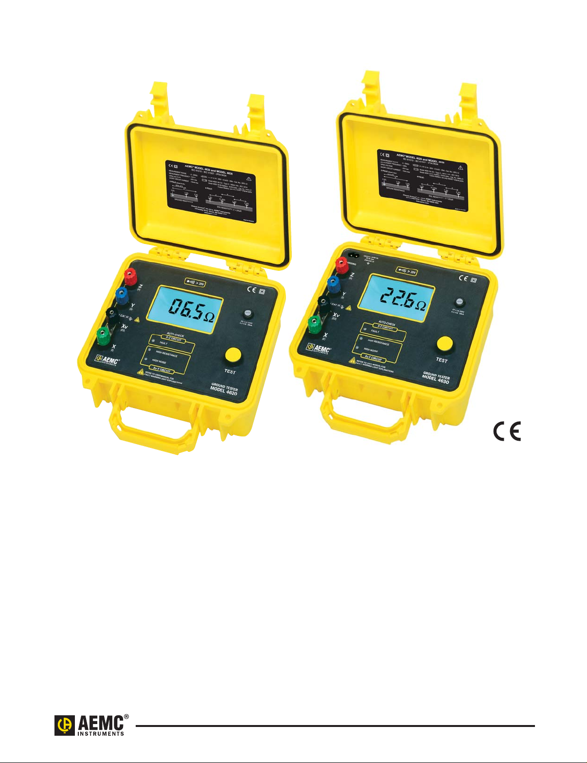
Digital Ground Resistance Tester
Models 4620 and 4630 perform ground
resistance and soil resistivity tests.
These direct reading testers measure
from 0 to 2000Ω, and are autoranging, so they automatically seek out
the optimum measurement range.
Easy-to-use — simply connect the
leads, Press-to-Measure and read
the results.
The large LCD (nearly
3
/4" high
characters) is easy-to-read, and also
indicates low battery status, overrange
and test lead shorts and lead reversals.
Three LED indicators on the front panel
continuously warn the user of
measurement problems to ensure
accurate and reliable tests.
The Models 4620 and 4630 are fuse
protected up to >250V
AC against
accidental connection to live circuits.
In the event of a system fault, they can
withstand 250V
AC with spikes of
3000V
AC or 1000VDC.
The heavy-duty field case is sealed
against dust and water when closed.
The meter itself is self-contained within
an inner case providing additional
environmental and insulation protection.
The test button is also sealed against
the elements.
The Model 4620 is powered by eight,
C cell batteries.
The Model 4630 is powered by 9.6V,
3.5 Ah NiMH rechargeable batteries. A
built-in recharge circuit, powered from
120/230V 50/60Hz line, also provides
for testing while recharging.
Both models will perform over 2000
15 second tests between recharging
(Model 4630) or battery replacement
(Model 4620).
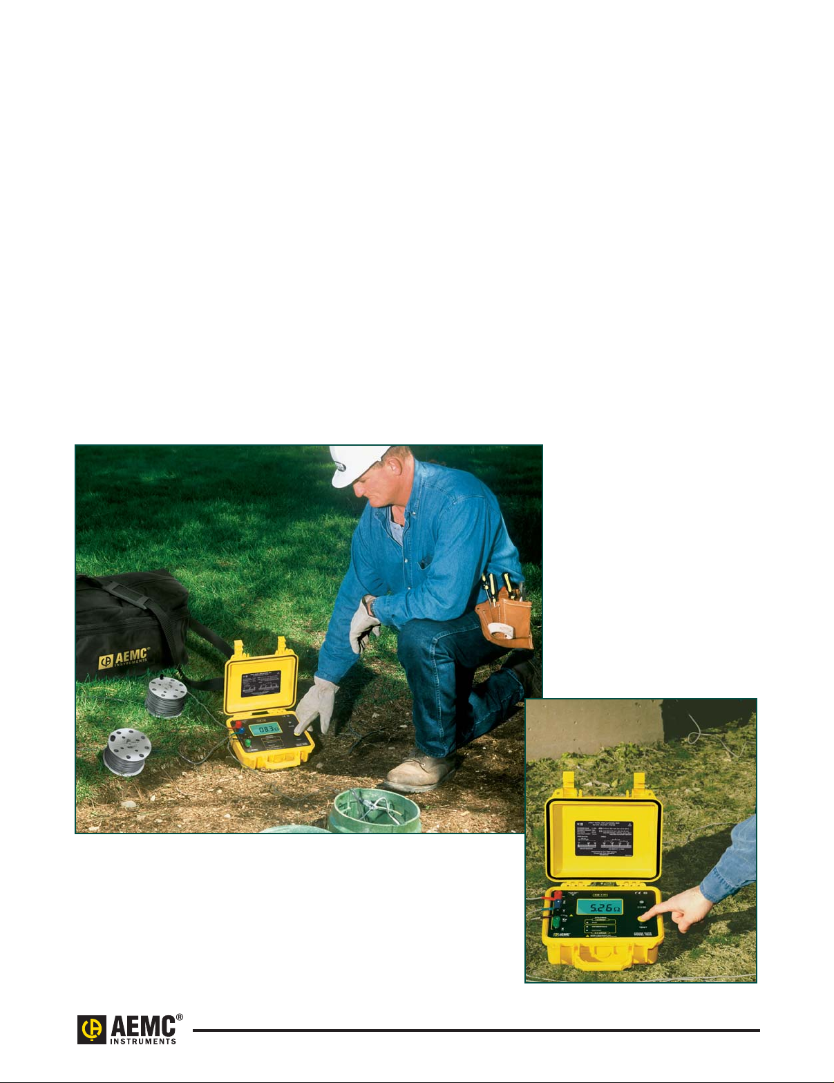
The Ground Resistance Tester
Models 4620 and 4630 are rugged,
easy-to-use instruments ideal for
maintenance crews performing
numerous tests. Both models exceed
mechanical and safety specifications
for shock, vibration and drop tests
called out in IEC standards. They are
designed to reject high levels of interference, so they can be used under
difficult conditions such as high stray
currents that normally affect accuracy.
Digital Ground Resistance Tester
Models 4620 & 4630
Page 2
Models 4620 & 4630 (pdf) 08/02
Technical Assistance (800) 343-1391 www.aemc.com 2 of 6
Features
• Measures soil resistivity (4-Point)
method
• Measures ground resistance (2- and
3-Point) Fall-of-Potential method
• Step voltage tests and touch
potential measurements
• Auto-Ranging: automatically selects
the optimum range
• Designed to reject high levels of
noise and interference
• Extremely simple to operate:
connect – press – read
• LED on faceplate informs operator of
high input noise, high auxiliary rod
resistance and fault connections
• Large easy-to-read backlit display
• Battery powered (Model 4620)
• AC powered with rechargeable
NiMH batteries (Model 4630)
• Rugged dustproof and rainproof
field case
• Can also be used for continuity
tests on bonding
• Color-coded terminals
Applications
• Three-Point measurements of
resistance to ground of ground
rods and grids. Three-Point mea-
surements are generally used when
the electrode or grid can be easily
disconnected, if corrosion is
suspected, or in circumstances where
ground faults are unlikely to occur.
• Four-Point tests or soil resistivity
measurements. Locating areas of
lowest soil resistivity is essential for
achieving an economical grounding
installation.
• Touch potential measurements, an
alternative to 3-Point tests in
evaluating electrical safety. This
test is recommended when the ground
cannot be disconnected, where
ground faults are highly likely to
occur, or when the “footprint” of
grounded equipment (the outline of
the part of equipment in contact with
the earth) is comparable to the size
of the ground to be tested.
• Two-Point tests for continuity tests
on bonding or on pre-established
grounds. This test is commonly
performed in urban environments
where proper auxiliary electrode
placement may be obscured by
confined real estate. Measurements
are referenced against a good local
ground conductor.
Page 3

Models 4620 & 4630 (pdf) 08/02
Technical Assistance (800) 343-1391 www.aemc.com 3 of 6
Specifications
MODELS 4620 4630
ELECTRICAL
Ranges (Auto-Ranging 0 to 2000Ω)20Ω 200Ω 2000Ω
Measurement 0.00 to 19.99Ω 20.0 to 199.9Ω 200 to 1999Ω
Resolution 10mΩ 100mΩ 1Ω
Open Voltage ≤42V peak ≤42V peak ≤42V peak
Resistance Measurement
128Hz square wave 128Hz square wave 128Hz square wave
Frequency
Test Current 10mA 1mA 0.1mA
Accuracy ±2% of Reading ± 1ct ±2% of Reading ± 1ct ±2% of Reading ± 3cts
Auxiliary Electrode Influence
Max Res. in Current Circuit 3kΩ 30kΩ 50kΩ
Max Res. in Voltage Circuit 2000Ω 50kΩ 50kΩ
Interference Rejects high levels of interference voltage (DC, 50 to 60Hz, harmonics):
DC voltage in series with X: 20V; AC voltage in series with Y: 13V peak;
AC voltage in series with Z: 32V peak
Response Time Approximately 4 to 8 seconds for a stabilized measurement
Withstanding Voltage 250VAC or 100VDC
Power Source Eight C cell batteries; 120/230V 50/600Hz
Alkaline recommended; Rechargeable 9.6V, 3.5 Ah NiMH batteries
Battery Life 1800 15-second measurements; LO BAT indication on LCD
Fuse Protection 0.1A, >250V, 0.25 x 1.25"; 30kA Interrupt Capacity
MECHANICAL
Display 3
1
/2 digit, 0.71" (18mm) high; 2000-counts; electroluminescent blue backlight
LCD also indicates overrange, test lead shorts and lead reversals
Connection Color-coded terminals accept spade lugs with min. gap of 6mm or
standard 4mm banana jacks
LED Indication Three LEDs indicate high input noise, high auxiliary rod resistance,
open leads, blown fuse
Operating Temperature 14° to 131°F (-10° to 55°C), 20 to 90% RH
Storage Temperature -40° to 158°F (-40° to 70°C), 10 to 90% RH with batteries removed
Dimensions 10.8 x 9.7 x 5.0" (273 x 247 x 127mm)
Weight 6.28 lbs (2.85kg) 7.38 lbs (3.35kg)
Case Heavy duty o-ring sealed field case
Mechanical Shock IEC 68-2-27
Vibration Test IEC 68-2-66
Drop Test IEC 68-2-32
Dielectric Test 3kV, 50/60Hz, 1 min. between four interconnected measuring terminals
and any external metal ground
Environmental O-ring sealed against dust and water to IP50 (Protection Index)
when case is closed
SAFETY
Rating EN 61010-1, Cat. III, Pollution Degree 2
CE Mark Yes
Page 4

Models 4620 & 4630 (pdf) 08/02
Technical Assistance (800) 343-1391 www.aemc.com 4 of 6
Ground Resistance Tester Model 4630 Kit
includes meter, two 300 ft color-coded
leads on spools, two 100 ft color-coded
leads, four 16" auxiliary ground
electrodes, one 16 ft lead with Mueller
®
clip, carrying bag, one 100 ft tape
measure, one AC power cord,
ground workbook and user manual
Test Kit – 4-Point includes carrying bag, two 300 ft color-
coded leads on spools, two 100 ft color-coded leads, four
16" auxiliary ground electrodes, one 16 ft lead with
Mueller
®
clip and one 100 ft tape measure
Catalog #2130.63
Test Kit – 3-Point includes carrying bag,
two 150 ft color-coded leads on spools,
two 16" auxiliary ground electrodes, one 16 ft lead with
Mueller
®
clip and one 100 ft tape measure
Catalog #2130.62
Ground Test Kit – 3-Point (supplemental 4-Point) includes
carrying bag, two 100 ft color-coded leads,
one 16 ft lead and two 16" auxiliary ground electrodes
Catalog #2130.61
The Models 4620 and 4630 are
built into a double case.This extra
rugged construction provides
double insulation, maximum field
durability and ease of serviceability.
Accessories
Page 5

Models 4620 & 4630 (pdf) 08/02
Technical Assistance (800) 343-1391 www.aemc.com 5 of 6
ORDERING INFORMATION CATALOG NO.
Ground Resistance Tester Model 4620 (4-Point, Digital, Battery Powered). . . . . . . . . . . . . . . . . . . . . . . . . . . . . . . Cat. #2130.43
Includes meter, eight C cell batteries and user manual
Ground Resistance Tester Model 4630 (4-Point, Digital, Rechargeable Battery). . . . . . . . . . . . . . . . . . . . . . . . . . . . . . . . . . Cat. #2130.44
Includes meter, battery, AC Power cord and user manual
Ground Resistance Tester Model 4620 Kit (4-Point, Digital, Battery Powered) . . . . . . . . . . . . . . . . . . . . . . . . . . . . . . . . . . . Cat. #2130.45
Includes meter, 8 C cell batteries, two 300 ft color-coded leads on spools, two 100 ft color-coded leads, four 16" auxiliary
ground electrodes, one 16 ft lead with Mueller
®
clip, carrying bag, one 100 ft tape measure, ground workbook and user manual
Ground Resistance Tester Model 4630 Kit (4-Point, Digital, Rechargeable Battery). . . . . . . . . . . . . . . . . . . . . . . . . . . . . . . Cat. #2130.46
Includes meter, two 300 ft color-coded leads on spools, two 100 ft color-coded leads, four 16" auxiliary ground electrodes,
one 16 ft lead with Mueller
®
clip, carrying bag, one 100 ft tape measure, one AC power cord, ground workbook and user manual
Accessories (Optional)
25Ω Calibration Checker (for Model 4620 and Model 4630). . . . . . . . . . . . . . . . . . . . . . . . . . . . . . . . . . . . . . . . . . . . . . . . . . . . Cat. #2130.59
Tape Measure (100 ft). . . . . . . . . . . . . . . . . . . . . . . . . . . . . . . . . . . . . . . . . . . . . . . . . . . . . . . . . . . . . . . . . . . . . . . . . . . . . . . . . . . Cat. #2130.60
Ground T est Kit – 3-Point (supplemental 4-Point) . . . . . . . . . . . . . . . . . . . . . . . . . . . . . . . . . . . . . . . . . . . . . . . . . . . . . . . . . . . . Cat. #2130.61
Includes carrying bag, two 100 ft color-coded leads, one 16 ft lead and two 16" auxiliary ground electrodes
Test Kit – 3-Point . . . . . . . . . . . . . . . . . . . . . . . . . . . . . . . . . . . . . . . . . . . . . . . . . . . . . . . . . . . . . . . . . . . . . . . . . . . . . . . . . . . . . . . Cat. #2130.62
Includes carrying bag, two 150 ft color-coded leads on spools, two 16" auxiliary ground electrodes,
one 16 ft lead with Mueller
®
clip and one 100 ft tape measure
Test Kit –4-Point . . . . . . . . . . . . . . . . . . . . . . . . . . . . . . . . . . . . . . . . . . . . . . . . . . . . . . . . . . . . . . . . . . . . . . . . . . . . . . . . . . . . . . . Cat. #2130.63
Includes carrying bag, two 300 ft color-coded leads on spools, two 100 ft color-coded leads, four 16" auxiliary
ground electrodes, one 16 ft lead with Mueller
®
clip and one 100 ft tape measure
11
11. Low battery indicator
12. Display
13. Fuse holder
14. Test button
15. Xv-Y high noise indicator
16. Xv-Y high resistance indicator
17. X-Z fault indicator
18. Electrode terminal X (E)
19. Electrode terminal Xv (ES)
10. Electrode terminal Y (S)
11. Electrode terminal Z (H)
12. AC power input
1 2
10
9
8
7
3
4
5
6
Page 6

Models 4620 & 4630 (pdf) 08/02
Technical Assistance (800) 343-1391 www.aemc.com 6 of 6
Contact Us
United States & Canada:
Chauvin Arnoux
®
, Inc.
d.b.a. AEMC
®
Instruments
200 Foxborough Blvd.
Foxborough, MA 02035 USA
(508) 698-2115 • Fax (508) 698-2118
www.aemc.com
Customer Support – for placing an order, obtaining price & delivery:
customerservice@aemc.com
Sales Department – for general sales information:
sales@aemc.com
Repair and Calibration Service – for information on repair & calibration, obtaining a user manual:
repair@aemc.com
Technical and Product Application Support – for technical and application support:
techinfo@aemc.com
Webmaster – for information regarding www.aemc.com:
webmaster@aemc.com
South America, Central America, Mexico, Caribbean, Australia & New Zealand:
Chauvin Arnoux
®
, Inc.
d.b.a. AEMC
®
Instruments
15 Faraday Drive
Dover, NH 03820 USA
(978) 526-7667 • Fax (978) 526-7605
export@aemc.com
www.aemc.com
All other countries:
Chauvin Arnoux SCA
190, rue Championnet
75876 Paris Cedex 18, France
33 1 44 85 45 28 • Fax 33 1 46 27 73 89
info@chauvin-arnoux.com
www.chauvin-arnoux.com
 Loading...