

Page 1
Model 4500 (pdf) Rev. 04 11/04
Technical Assistance (800) 343-1391 www.aemc.com 1 of 5
Digital Ground Resistance Tester
Model 4500
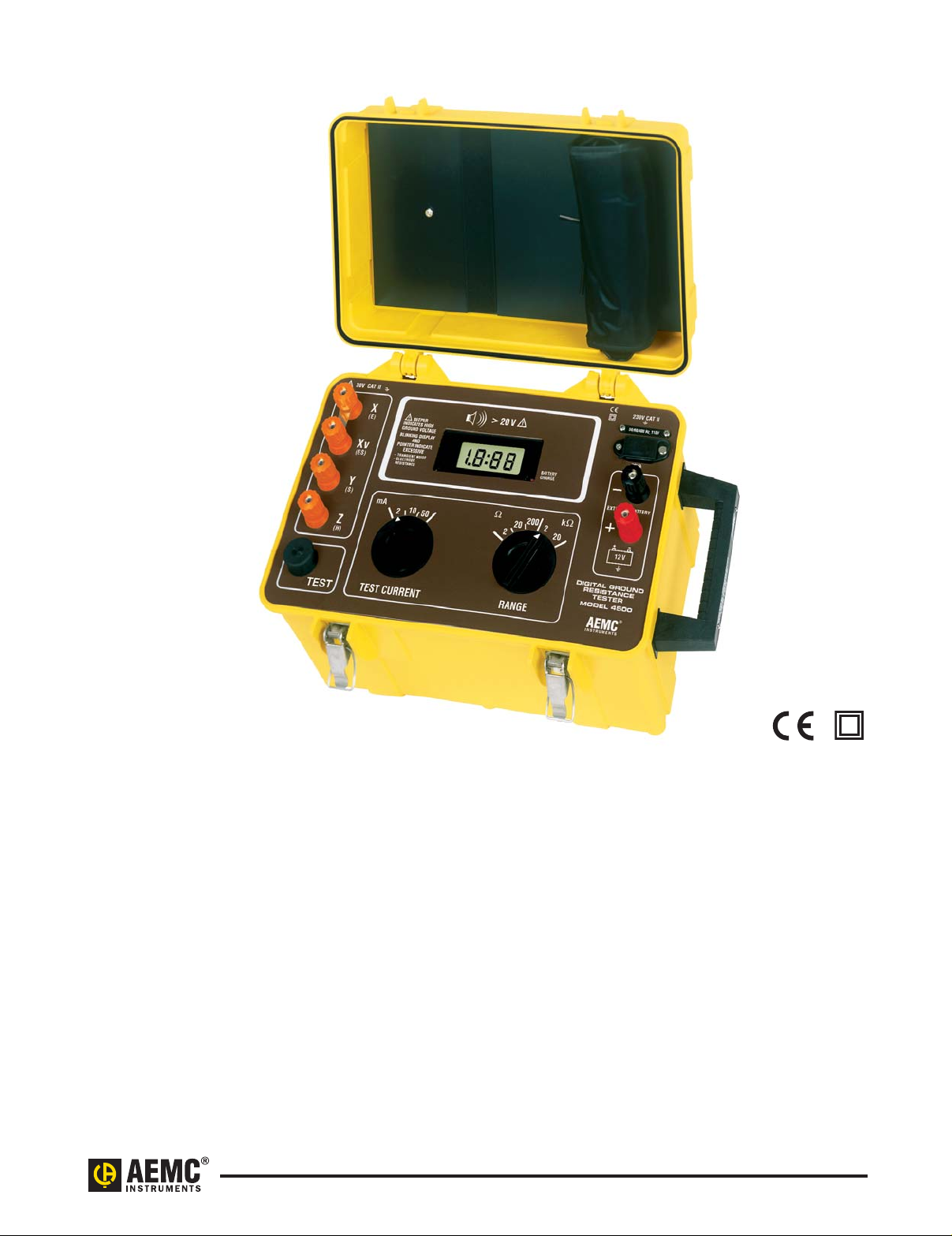
The Digital Ground Resistance Tester
Model 4500 is designed for measuring
very low resistance on large grounding
systems, such as ground grids and
ground mats.
It rejects high levels of interference
voltages at DC or 60Hz and its
harmonics, and can be used under
difficult conditions such as high stray
currents or excessive auxiliary electrode resistance without substantially
affecting accuracy.
The Model 4500 has three selectable
test current ranges (2, 10, 50mA) and
five selectable resistance testing
ranges (2Ω, 20Ω, 200Ω, 2000Ω and
20kΩ). It is capable of direct readings
with a resolution as low as 1mΩ.
With such a wide resistance capability,
the Model 4500 is capable of measuring
the resistivities of soil and other materials
from below 10mΩ-cm to over 1MΩ-cm.
Readings are displayed on a large
(0.71"), 3
1
/2digit LCD. The LCD blinks
and a pointer on the display lights to
warn of excess stray current or auxiliary
electrode resistance, or when there is a
lack of continuity between leads and
electrodes. Abeeper will notify the user
if voltage greater than 20 volts peak is
present between terminals X (C1) and
Y (P2) or X and Z (C2) when the
ground leads are connected.
The instrument is fuse protected up
to 500A
AC to protect the instrument
against voltage into the test leads.
Power is supplied by a rechargeable
12V battery; the tester may also be
operated from an external 12V
DC supply.
Abattery charge indicator and low
battery indicator appear on the LCD
and a dual-voltage charging unit is built
into the instrument.
The heavy-duty, safety yellow case
is dust and water resistant to ensure
reliable field use. The cover may be
detached while the meter is in use,
if desired. Optional test kits are
available for ground resistance and
soil resistivity tests.
Page 2

Model 4500 (pdf) Rev. 04 11/04
Technical Assistance (800) 343-1391 www.aemc.com 2 of 5
Specifications
ELECTRICAL
Ranges 2Ω 20Ω 200Ω 2000Ω 20kΩ
Resolution 1mΩ 10mΩ 0.1Ω 1Ω 10Ω
Resistance Measurement
Frequency
128Hz square wave
Test Current 2mA, 10mA, 50mA
Accuracy ±2% of Reading ± 1ct from 10% to 100% of range
Auxiliary Electrode Ry: 50kΩ on 20Ω, 200Ω, 2000Ω & 20kΩ ranges; 5kΩ on 2Ω range
Resistance Rz: 2mA range: 15kΩ; 10mA range: 3000Ω; 50mA range: 400Ω
Interference The unit is designed to reject high levels of interference voltages
at DC, or 50/60 Hz and their harmonics
Noise Influence
0.5% of range (max) to 20V peak
on Accuracy
Power Source Built-in rechargeable 12V, one Ah NiCD battery, or external 12 V
DC; low battery indication.
Battery can be recharged with built-in dual voltage charging unit:
94 to 127V or 187 to 253V (47 to 450Hz)
Charging Time 14 hours typical
Charging Supply Voltage Internally selectable 110/220V, 45 to 450Hz
Battery Life Four hrs on 50mA test current (800 15 sec measurements),
Seven hrs on 2mA and 10mA test currents (1500 15 sec. measurements)
Fuse Protection 500Vrms measurement circuit
MECHANICAL
Display 7-segment LCD, 0.71" (18mm) high (31/2digit); 2000-count
Connection Terminals accept spade lugs with min. gap of 6mm or
standard 4mm banana jacks
Operating Temperature 14° to 122°F (-10° to 50°C)
Dimensions 15.75 x 10.2 x 9.8" (400 x 260 x 250mm)
Weight 14 lbs (6.5kg) approximate
Case Heavy-duty plastic, with detachable cover and carrying handle
Colors Case: safety yellow; Front panel: brown
Dielectric Test 2000Vrms, 50/60Hz between 4 interconnected measuring terminals
and any external metal ground; 2000Vrms, 50/60Hz between line input
and measuring terminals on front panel
Environmental O-ring sealed faceplate against water and dust; sealed cover
when closed; IEC529, DIN 0470-T1
SAFETY
Rating EN 61010
Double Insulation Yes
Impact Resistance Shock and vibration according to MIL-T-28800D class 3
CE Mark Yes
Features
• Measures soil resistivvity (4-Point)
• Measure ground resistance (2- and
3-Point) Fall-of-Potential Method
• Step voltage tests and touch
potential measurements
• Selectable: three test currents and
five resistance ranges
• Measures very low resistance on
large grounding systems and grids
• High test current also enables
geological surveys
• Large easy-to-read LCD
• Display includes indicators for excess
stray current and voltage, high
auxiliary rod resistance and fault
connection
• Battery (rechargeable) powered or
external 12V
DC
• Rugged dustproof and rainproof
field case
• Can be used for continuity tests
on bonding
• Includes power cord, 12V NiCD
battery, hex key, spare fuse and
user manual
Applications
• Three-point measurement of large
grounding grids, counterpoises,
ground mats and grounded
equipment.
• Soil resistivity tests (4-Point
measurement), commonly performed
by utilities at proposed construction
sites. Using soil resistivity analysis,
the size and complexity of grounding
system construction can be evaluated. The Ground Resistance Tester
Model 4500 will measure the resistivity of epoxies, cement, ground
enhancement materials and many
other substances.
• Step or touch potential levels under
true fault conditions can be determined by using the Model 4500 to
inject a simulated low-level fault into
an electrical system. When used in
this fashion, the Model 4500 will
display readings in volts per fault
ampere.
• Two-point tests for continuity tests
on bonding or on pre-established
grounds.
Page 3

Model 4500 (pdf) Rev. 04 11/04
Technical Assistance (800) 343-1391 www.aemc.com 3 of 5
Accessories
Test Kit includes 30 ft lead,
canvas bag, two 500 ft reels,
two 16" auxiliary ground electrodes
Catalog #100.525
Test Kit includes two 100 ft leads,
one 16 ft lead, two 16" auxiliary
ground electrodes, canvas bag
Catalog #2130.61
Page 4

Model 4500 (pdf) Rev. 04 11/04
Technical Assistance (800) 343-1391 www.aemc.com 4 of 5
ORDERING INFORMATION CATALOG NO.
Ground Resistance Tester Model 4500 (4-Point Digital) . . . . . . . . . . . . . . . . . . . . . . . . . . . . . . . . . . . . . . . . . . . . . . Cat. #450.100
Includes batteries, AC supply cord and user manual
Accessories (Optional)
Test Kit for Model 4500 includes carrying bag, set of two 500 ft leads on orange reels,
one 30 ft lead, two auxiliary ground electrodes. . . . . . . . . . . . . . . . . . . . . . . . . . . . . . . . . . . . . . . . . . . . . . . . . . . . . . . Cat. #100.525
Ground Test Kit – 3-Point (supplementa 4-Point) includes carrying bag, two 100 ft color-coded leads,
one 16 ft lead and two 16 " auxiliary ground electrodes . . . . . . . . . . . . . . . . . . . . . . . . . . . . . . . . . . . . . . . . . . . . . . . . Cat. #2130.61
1 5432
11. Ground resistance
measurement strip
12. Incorrect measurement indicator
13. Display
14. Low battery indicator
15. Battery change indicator
16. Supply voltage indicator
17. AC power supply input jack
18. Connecting terminals for
external 12V
DC
19. Range selector
10. Test current selector
11. Push-to-Measure
12. Input Measurement Terminals
13. Adhesive label for C-1, P-1,
P-2, C-2 terminal option
12
11
!
X
X
v
BEEPER
INDICATES HIGH
GROUND VOLTAGE
BLINKING DISPLAY
AND
POINTER INDICATE
EXCESSIVE
- TRANSIENT NOISE
- ELECTRODE
RESISTANCE
Y
mA
10
50
2
Z
TEST RANGETEST CURRENT
10
50/60/400 Hz_110V
6
7
BATTERY
CHARGE
EXTERNAL BATTERY
200
20
2
k
2
20
12 V
DIGITAL GROUND
RESISTANCE
TESTER
MODEL 4500
8
9
C1
13
P1
P2
C2
Page 5

Model 4500 (pdf) Rev. 04 11/04
Technical Assistance (800) 343-1391 www.aemc.com 5 of 5
Contact Us
United States & Canada:
Chauvin Arnoux
®
, Inc.
d.b.a. AEMC
®
Instruments
200 Foxborough Blvd.
Foxborough, MA 02035 USA
(508) 698-2115 • Fax (508) 698-2118
www.aemc.com
Customer Support – for placing an order, obtaining price & delivery:
customerservice@aemc.com
Sales Department – for general sales information:
sales@aemc.com
Repair and Calibration Service – for information on repair & calibration, obtaining a user manual:
repair@aemc.com
Technical and Product Application Support – for technical and application support:
techinfo@aemc.com
Webmaster – for information regarding www.aemc.com:
webmaster@aemc.com
South America, Central America, Mexico, Caribbean, Australia & New Zealand:
Chauvin Arnoux
®
, Inc.
d.b.a. AEMC
®
Instruments
15 Faraday Drive
Dover, NH 03820 USA
(978) 526-7667 • Fax (978) 526-7605
export@aemc.com
www.aemc.com
All other countries:
Chauvin Arnoux SCA
190, rue Championnet
75876 Paris Cedex 18, France
33 1 44 85 45 28 • Fax 33 1 46 27 73 89
info@chauvin-arnoux.com
www.chauvin-arnoux.com
 Loading...