

Page 1

Outside plant technicianshave to
perform a number of tasks: install
apparatus cases and splice cables;
locate and repair span faults such as
bridged taps, load coils, shorts, opens;
and verify that cable meets carrier
requirements prior to Central Office
or Customer Premise equipment
installations. With this multitude of
tasks, outside plant technicians need a
solution that enables them to perform
extensive physical layer testing in an
all inclusive, easy-to-use test set.
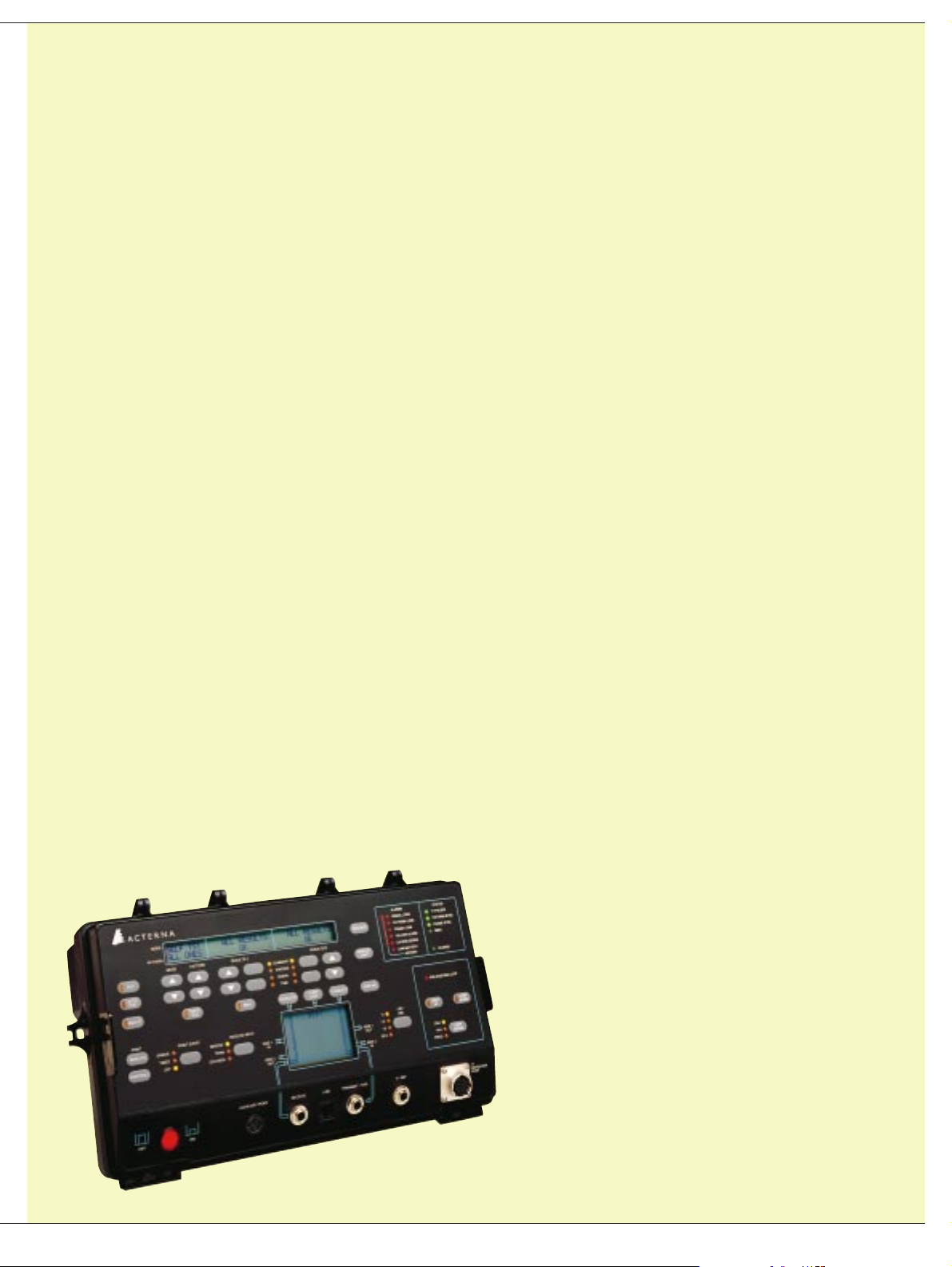
The Acterna T-BERD Outside Plant
Tester (209OSP) is a complete tool
that meets the exclusive testing
requirements of the outside plant
technicians. It combines copper
prequalification features (TDR and DC
measurements) with service turn-up
and troubleshooting features for
T1/FT1/HDSL/ISDN /DDStechnologies. The combination of copper
analyzer and digital loop tester
features makes the T-BERD Outside
Plant Tester the most flexible, all-inone solution for outside plant testing.
Highlights
– Copper analysis with DC measure-
ments and graphical TDR
– Combined testing of digital
services and circuits – T1, HDSL,
DDS and ISDN
– Field-upgradeable software allows
for building a custom test set
– Rugged NEMA 4X compliant
design endures the harsh
weather conditions
– Battery-powered operation allows
for field-portable testing
– Reliable testing and proven
performance
Simplifying test procedures with one complete solution
Acterna T-BERD Outside Plant Tester (209OSP)
Page 2
2
Applications
The T-BERD Outside PlantTester can
verify physical layer functionality by
performing standard BER testing.
In addition, it performs DC measurements to accurately identify copper
faults. The TDR’s graphical display
allows the technician to view the
respective faults and confirm the
location, as well asthe type of fault.
Along with BER testing, the T-BERD
Outside Plant Tester can use intelligent
repeater technology to sectionalize
span problems, while the preprogrammed loop codes enable the user
to loopback variousequipment on
the span. When equipped with the
HDSL/ISDN/DDS Measurement
Option, the T-BERD Outside Plant
Tester is able to perform loss measurements at various frequencies to assure
proper signal level on the span for
HDSL, ISDN, BRI, and DDS circuits.
Test copper loops
In order to verify that the copper loop is
able to support digital service such as a
T1, the copper facility hasto be tested.
To effectively test the loop, technicians
need a digital volt ohmmeter (DVOM)
and TDR to determine the physical
impairments and measure the distance
to the fault. The T-BERD Outside Plant
Tester’s DCMeasurement Option,
along with the TDR Option, allow the
technician to effectively prequalify the
copper loop.
DCMeasurement Option
This option enables the T-BERD
Outside Plant Tester to perform ohm,
amp, and, voltage measurements:
– ‘Ohm measurements’ allow the
technician to quickly identify physical
impairments, such as opens, shorts,
grounds, and one-side faults with
automated resistance measurements
between tip, ring, and ground
– ‘Amp measurements’ immediately
detect one-side faults, such asopens
and grounds, with an automated
current measurement between tip
and ring; Automated voltage measurements help isolate bad repeaters and
span-powering problems
A complete solution, the T-BERD
Outside Plant Tester provides:
– One tool, multiple tasks
Cost savings through consolidation
of multiple test capabilities and
features (copper analysis, FT1/T1,
HDSL, DDS, ISDN, span sectionalization) into a single test set
– Investmentprotection
Customers can build a custom test
set for their testing needs with an
option of field-upgrading their unit
later with additional features at a
fraction of the cost of buying a
new test set
– Fastimplementation
A variety of accessories and features
with a common menu interface
reduces training time for technicians
and leads to quicker turn-ups and
closures of trouble tickets
– Reliability
T-BERD’s long-running reputation
for designing reliable test equipment
means customers can be assured
that their test set will notincur
unnecessary repair costs
Page 3

3
TDR Measurement Option
This option locates copper faults. The
T-BERD Outside PlantTester can be easily
configured for TDR measurement by
selecting the cable type and approximate cable length being used. By
completing these simple steps, the
cumbersome process of determining
complex constants such as pulse width
and pulse height is avoided. Once the
TDR is set up, the graphical display
on the mainframe front panel allows the
user to immediately view the TDR traces.
A built-in zoom feature facilitates fault
identification by focusing on copper
faults such as bridged taps, splits, load
coils, high-resistance opens, and bad
splices.Faultidentification isperformed
at the push of a button, with the distance
to the fault displayed in feet.
Turn Up and Troubleshoot
FT1/T1 Circuits
The T-BERD Outside PlantTester
mainframe features a full-span T1
transmitter and receiver used to
identify marginal troubles with all
standard T1 stress patterns at various
output levels. Automatic configuration
and results with summary functions
immediately identify the presence of
T1 pulses, pattern, framing, and error
status. Additionally, the mainframe
can qualify T1 spans with automated
MULTIPAT
™
and BRIDGTAP™stress
patterns. To stress the entire T1 span
and verify the error tolerance of
network equipment, the T-BERD
Outside Plant Tester can insert bit
errors and BPVs.
Fractional T1 (FT1) Option
This option enables the T-BERD
Outside Plant Tester to per form BER tests
on selected channels in order to verify
transmission on contiguousand noncontiguous FT1 bandwidth. It also
allows the technician to verify VF
circuit performance with 404, 1004,
2804, and 2713 Hz tones at various
output levels.
Standard T1/FT1 BER testing provides
the most accurate measure of pointto-point transmission performance
by stress-testing the circuits to
ensure proper circuit configuration.
The advanced software options that
complement T1/FT1 BER testing
include: Advanced Stress Patterns
Option, Channel Monitor Option,
Enhanced ESF Option and Smart
Loopback/Command Codes Option.
Advanced Stress Patterns Option
This option enables the technician to
stress repeatered T1/FT1 circuits with
a variety of stress patterns such as
55 octet, T1-DALY, and other long user
patterns as recommended bythe
ANSI T1.403 standard.
Channel Monitor Option
With this option, the T-BERD Outside
Plant Tester is able to simultaneously
monitor ABCD bits of all 24 timeslots,
listen to voice quality, and view the
data bits of individual DS0 channels.
Enhanced ESF Option
This option adds testing flexibility
to the T-BERD Outside PlantTester.
It enables the T-BERD Outside Plant
Tester to decode ESFone-second
broadcast performance report messages
(PRMs) to verify remote in-service
circuit performance. With this option,
the T-BERD Outside PlantTester can
also emulate ANSI T1.403-compatible
CSU equipment to verify proper operation during circuit installation and fault
isolation as well as query performance
monitoring NIU equipment to retrieve
in-service performance data to verify
remote circuit operation. This option
supports Westell
™
equipment.
Page 4

4
Smart Loopback/Command Code Option
This option enables the T-BERD Outside
Plant Tester to send and receive
commands for maintenance switch
operation to minimize circuit downtime
and query performance data. Thisoption
supports Teltrend
™
and Westell equipment. In addition, this option enables
the user to utilize intelligent repeater
technology to qualify and isolate
troubles on outside plant spans.
The use of preprogrammed loopcodes
for intelligent repeaters enables the
T-BERD Outside PlantTester to sectionalize span problems prior to dispatchi ng
maintenance personnel. It supports
Teltrend
™
, Westell, Wescom™, XEL™,
and TxPort
™
equipment. Please refer
to figure 1.
Test local loop for
HDSL/ISDN/DDS circuits
When equipped with the ‘HDSL/ISDN/
DDS MeasurementOption’, the T-BERD
Outside Plant Tester is able to perform
loss measurements at 28 kHz, 40 kHz,
48 kHz, 82 kHz, 163 kHz, 196 kHz, and
392 kHz to assure proper signal level at
equipment inputs for HDSL, BRI, and
DDS circuits. In addition, the user can
ensure that the local loop does not
exceed the customer service agreement requirements for maximum loop
length, including bridged tap length,
when provisioning HDSL, BRI, and
DDS circuits. This option also includes
preprogrammed HTU-C, HTU-R, and
doubler loop codes, which enable the
T-BERD Outside PlantTester to quickly
sectionalize transmission troubles.
The option supports PairGain
™
,
Tellabs
™
, Adtran™,Westell, and
ADC
™
equipment. Please refer to
figures 2 and 3.
Turn Up and Troubleshoot DLC systems
The DLC/DS0 Analyzer Lid Option is a
tool for verifying DLC/DS0 circuitsand
contains features that perform the
following functions:
– Fullduplex channelmonitor
The T-BERD Outside PlantTester can
decode signaling bits in both directions on all channelssimultaneously.
The technician can listen to either
one or both directions of a VF circuit
by dropping the channel(s) to the
internal speaker or an externalTIMS.
– Channel insert
Channel insert allows an internal
test tone or voice and digits from
an external butt-set to be inserted
and controls signaling bits without
disrupting the remaining active
channels.
figure 1 Use preprogrammed loop codes to sectionalize span
problems with the smart Loopback/Command Code Options
DSX-1
A-Side Z-Side
MON
Out
In
Intelligent
Office Repeater
T-BERD Outside Plant Tester
Distribution
Frame
Intelligent
Line Repeater
Intelligent
Line Repeater
NIU
Page 5

5
SLC-96 datalink monitor
The T-BERD Outside PlantTester can
capture major and minor shelf alarms,
far-end loopback, line protection
switches, and maintenance events in
both directions for nonintrusive,
in-service verification.
SLC-96 datalink emulation
The user can verify central office switch
and terminal response to alarms, far-end
loopbacks, and line protection switches
as well as execute test pair maintenance
requests during system installation
and in-service maintenance.
Two-Wire VF input/output
The T-BERD Outside PlantTester allows
a butt-set to be connected for DTMFdigit
transmission, call placement, and talk
path for subscriber maintenance and
PBX applications.
SLC-96 Mode 2 configuration timeslot
assignment results
The T-BERD Outside PlantTester can
determine channel and timeslot assignment for systems configured for SLC-96
Mode2 concentrated applications.
Please refer to figure 4.
figure 2 Measure total length of the loop, including bridged taps,
to verify that it meets CSA standards
figure 4 Ensure remote terminal operations, verify voice-grade service,
and validate signaling transmissions during system qualifications
CO CPE
T-BERD Outside Plant Tester
CO CPE
T-BERD Outside Plant Tester
T-BERD Outside Plant Tester
figure 3 Measure signal lossto qualify loop integrity prior to circuit turn-up
DSX-1Digital Switch Remote TerminalD Shelf
A-Side Z-Side
MON
Out
In
T-BERD Outside Plant Tester
DLC Analyzer
C Shelf
B Shelf
A Shelf
Rx Tx
Page 6

6
– HDSL remote access shelf
With the HDSL remote access shelf,
the user gains additional access
points on the HDSL span. The shelf
houses the HDSL transmission unit at
the remote site, namely a standard
200/400-mechanics HTU-R card.
Much like the HTU-C card within the
HDSL doubler power supply performs
T1-to-HDSL, the HTU-R within the
remote access shelf performs the
HDSL-to-T1 conversion. The remote
access shelfalso conta ins T1 jacks
that allow the T-BERD Outside Plant
Tester to perform BER testing.
Hardware accessories
Users can order accessories for the
T-BERD Outside PlantTester that can
enhance the test set’s functionality
in performing a number of testing
applications.
TroubleshootT1 spans
– Repeater adapter
The repeater adapter enables the
T-BERD Outside PlantTester to test
repeatered spans with a single cable.
During this process, the user can
control test access to easilysectionalize span trouble. The repeater
adapter allows testing toward the
customer or central office as well as
testing the repeater itself to sectionalize span trouble. It also provides
an additional access point, at the
repeater casing, along the T1 span.
– Repeater power supply
The repeater power supply powers-up
a T1 circuit from the main distribution
frame (MDF) which allows the T-BERD
Outside Plant Tester to test and
qualify circuits prior to installation
and connection of the central office
repeater. If the span is longer than
17 repeaters, the user can select a
current between 60 mA, 100 mA, and
140 mA to power-up longer spans.
The repeater power supply displays
span voltage and current for comparison with circuit design.
– Repeater power supply multiplexer
The repeater power supply multiplexer allows the user to switch
automatically between T1s in the
field. It can remotely switch power
between up to six T1 spansand
provide regenerative signal
loopback for single-technician
applications. It may be used with
standard and intelligent line repe ater s.
Turn Up and Troubleshoot HDSL spans
– HDSL doubler power supply
With the HDSL doubler power supply,
the technician can access the span at
the MDF and emulate the HDSL transmission unit at the central office
(HTU-C) by housing the 220 mechanics HTU-C card. The HTU-C card inside
the doubler power supply performs
T1-to-HDSL conversion and supplies
the appropriate span power. The front
panels of the doubler power supply
contain T1 jacks that allow the T-BERD
Outside Plant Tester to per form BER
testing. In addition, the T-BERD
Outside Plant Tester can provide
loopback capabilities using preprogrammed HTU-C, HTU-R, and doubler
loopcodes.
Page 7

7
Package descriptions
209OSP-P1
Mainframe, DC Measurements, TDR Measurements,
Repeater Adapter
209OSP-P2
Mainframe, DC Measurements, TDR Measurements,
HDSL/ISDN/DDS Measurements, Repeater Adapter
209OSP-P3
Mainframe, DC Measurements, TDR Measurements,
Channel Monitor, Advanced Stress Patterns,
Enhanced ESF, Smart Loopback/Command Codes,
FT1, Repeater Adapter
209OSP-P4
Mainframe, DC Measurements, TDR Measurements,
Channel Monitor, Advanced Stress Patterns,
Enhanced ESF, Smart Loopback/Command Codes,
FT1, HDSL/ISDN/DDS Measurements, Repeater
Adapter
Ordering information
Mainframe
– 209OSP T-BERD T-Carrier Analyzer
Options
– 209OSP-1 DC Measurements
– 209OSP-2 TDR Measurements
– 209OSP-3 Channel Monitor
– 209OSP-4 Advanced Stress patterns
– 209OSP-5 Enhanced ESF
– 209OSP-6 Smart Loopback/Command Codes
– 209OSP-7 Fractional T1
– 209OSP-8 HDSL/ISDN/DDS Measurements
– 209OSP-96 DLC/DS0 Analyzer Lid
Upgrades
– 209OSP-UPG1 Cable Qualification
– 209OSP-UPG2 Advanced Services/Intelligent
Network Support
– 209OSP-UPG3 HDSL/ISDN/DDS Measurements
– 209OSP-UPG4 HDSL/Advanced Services/
Intelligent Network Support
Accessories
– 41084 T-BERD Repeater Power Supply
– 43141
T-BERD Repeater Power Supply Multiplexer
– 44116 T-BERD HDSL Doubler Power Supply
– 44527 T-BERD HDSL Remote Access Shelf
– 41754 T-BERD Repeater Adapter
– 41157 T-BERD Repeater Extender
– PR-40A Thermal Graphics Printer with
Carrying Case
– 10966 Thermal Printer Paper
– CC-42215 Soft Carrying Case for Outside
Plant Tester
– CC-42632 Soft Carrying Case for Repeater
Power Supply
– CC-OSPLID Soft Carrying Case for Outside
Plant Tester Lid
Technical specifications
Mainframe specifications
Operating modes
– Self Test
– Automatic Configuration
– T1 Unframed
– T1 D4
– T1 ESF
– T1 SLC Framed
– T1 DID Framed
– FT1 D4 Framed*
– FT1 ESF Framed*
– T1 Test Loopback
– T1 Line Loopback
– Repeater Test*
– DC Measurements*
– TDR Measurements*
– HDSL Measurements*
– SMARTNIU Measurements*
Patterns
– All Ones
– 1:1
– 1:7
– 2 in 8
– 3 in 24
– 63*
– 511*
– 2047*
– T1 QRSS
– BRIDGTAP
™
– MULTIPAT
™
– Programmable (3 to 24 bits) (3)
– All Zeroes
– 404, 1004, 2804, 2713 Hz*
– T1-Daly
– T1-2/96*
– T1-3/54*
– T1-4/120*
– T1-5/53*
– 55 Octet*
– MIN/MAX*
Input and output connectors
– WECO 310, T1 Repeater Port,
– 8 pin RS-232, RJ48
Input impedance
– BRIDGE 1000 W with ALBO
– TERM 100 W with ALBO
– DSX-MON 100 W with AGC
Receive level
– BRIDGE or TERM +6 to –35 dBdsx
– DSX-MON +6 to –24 dBdsx
Level measurement
– +6.0 to –40.0 dBdsx,
– +6.0 to –6.0: 0.1 dB resolution
– –6.0 to –40.0: 0.5 db resolution
Frequency measurement
– 1 Hz resolution; 5 ppm accuracy
Transmit timing sources
– Internal Clock
– Recovered Clock
Line codes
– AMI, B8Zs
Loopback codes
– CSU
– CSU Line (ESF)
– CSU Payload (ESF)
– NIU (FAC1, FAC2, FAC3)
– NIU Network (ESF)
– Programmable (3 to 8 bit)
– Intelligent Repeaters*
– HDSL End-Equipment*
DC measurements*
– Resistance 10 W to 10 MW
– Volts DC 0.5 to 400 VDC
– Simplex Current 0 to 200 mA
TDR measurements*
– Pulse Amplitude 10.0 V p-p
– Measurement Range 50 to 10,500 ft
HDSL measurements*
– Loop Loss 0.0 dB to 40.0 dB
– Accuracy ±0.5 dB
– Resolution 0.1 dB
– Loop Length 100 to 20,000 ft
– Capacitance 1500 pF to 323,500 pF
– Power -40.0 to +13.0 dBm
Power
– AC Operating and Charging Power
115 VAC ±10%, 50-60 Hz
– Battery Type Lead Acid
– Battery Operation 5 hours (nominal)
– Battery Charging Time 8 hours (nominal)
Physical characteristics
– Enclosure Dimensions (h x w x d)
7.0 x 13.6 x 7.8 in
(17.8 x 34.5 x 19.8 cm)
– Weight 1.4 lb (5.6 kg)
Operational characteristics
– Battery Operating Temperature. –20 to 50ºC
– AC Operating Temperature –20 to 40ºC
– Storage Temperature –20 to 60ºC
– DLC/DS0 Specifications
*Optional
Page 8

Worldwide
Headquarters
20400 Observation Drive
Germantown, Maryland
20876-4023
USA
Acterna is present in more
than 80 countries. To find
your local sales office goto:
www.acterna.com
Regional Sales
Headquarters
North America
20400 Observation Drive
Germantown, Maryland
20876-4023
USA
TollFree: +1866 228 3762
Tel: +1 301 353 1550
Fax:+1301 444 8468
Latin America
Av. Eng.Luis Carlos Berrini
936/8° e 9° andares
04571-000 São Paulo
SP-Brazil
Tel: +55 11 5503 3800
Fax:+55 11 5505 1598
Asia Pacific
42 Clarendon Street
PO Box 141
South Melbourne
Victoria 3205
Australia
Tel: +61 3 9690 6700
Fax:+61 3 9690 6750
Western Europe
Arbachtalstraße 6
72800 Eningen u.A.
Germany
Tel: +49 7121 86 2222
Fax:+49 7121 86 1222
Eastern Europe,
Middle East & Africa
Elisabethstraße 36
PO Box 13
2500 Baden
Austria
Tel: +43 2252 85 521 0
Fax:+43 2252 80 727
1st Neopalimovskiy Per.
15/7 (4th floor)
RF 119121 Moscow
Russia
Tel: +7 095 248 2508
Fax:+7 095 248 4189
© Copyright 2002
Acterna, LLC.
All rights reserved.
Acterna, The Keepers of
Communications, and
its logo are trademarks
of Acterna, LLC. All
other trademarks and
registered trademarks
arethe property of their
respective owners. Major
Acterna operations sites
are IS0 9001 registered.
Note: Specifications,
terms and conditions
are subject to change
without notice.
DLC/DSO lid specifications
– Automatic Configuration
– SLC-M1 (SLC-6 Mode 1) Framed
– SLC-M2 (SLC-96 Mode 2) Framed
– T1 DID Framed
– T1 D4 Framed
– T1 ESF Framed
Channel insert sources
– VF PCM Tones 404, 1001, 2804 Hz
–16, –10, –3, 0, +3 dBm
– Two-Wire VF Interface
Signaling insert sources
– A, B, C, D
– On-hook, Off-hook, Ring
Datalink insert sources
– Major Alarm Shelf A, B, C, D, No Shelf
– Minor Alarm
– Power/Miscellaneous Alarm
– Far-end Loopback Shelf A, B, C, D, Protect
– Switch to Protect Shelf A, B, C, D
– Maintenance Test
– Idle
Input and output connectors
– WECO 310, Two-Wire VF Posts
Input impedance
– BRIDGE 1000 W with ALBO
– TERM 100 W with ALBO
– DSX-MON 100 W with AGC
Line codes
– AMI, B8ZS
Power
– 115 VAC ± 10%, 50-60 Hz
Physical characteristics
– Enclosure Dimensions (h x w x d)
7.8 x 13.7 x 4.4 in
– Weight 4.5 lb (2.0 kg)
Operational characteristics
– Operating Temperature 32 to 122ºF
(0 to 50ºC)
*Optional
TB2090SP/DS/ACC/01-02/AE/PDF ONLY/ACTOOO67
 Loading...