

Page 1
Features
Broadband: 30 MHz - 2000 MHz
Minimizes antenna switching
Transmit and receive capabilities
Individual calibration
Two year warranty
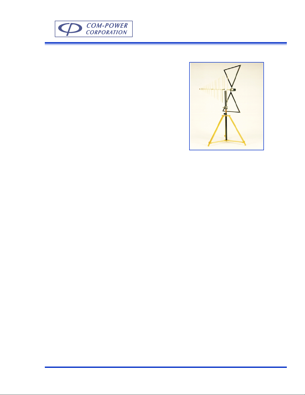
Combilog Antenna
AC-213, A C-220
Description
The Combilog antennas are broadband antennas designed to operate in the 30 MHz - 2000 MHz frequency range for electromagnetic compatibility testing. The Combilog antenna combines the electrical
properties of a biconical antenna and a log periodic
antenna.
T wo Combilog antenna models are av ailable. The y are
AC-213 and AC-220. The model AC-213 has a frequency range of 30 MHz -1300 MHz. The model AC220 has a frequency range of 30 MHz to 2000 MHz.
The antenna is shipped with an insulated mounting
tube. This tube can also be adapted for mounting the
antenna to an antenna mast or tripod. The antenna
also has a polarization adjustment joint . The polarization of the antenna can be easily changed (Vertical
or Horizontal) during testing by using this joint.
The elements are constructed using aluminum with
corrosion resistant conductive coating. The rear triangle elements can be removed for storage and transportation.
Application
The Combilog antennas are designed for emissions
and susceptibility testing to verify compliance to FCC,
IEC, CISPR, FAA and MIL-STD specifications.
The main advantage of a Combilog antenna is that it
covers the frequency range of the Biconical and Log
Periodic antenna. This eliminates antenna switching
(typically at 300 MHz) and allows continuous sweep
measurement without a frequency band break. The
broadband matching network located in the rear improves antenna response at the lower frequencies.
For susceptibility testing the Combilog antenna can
be used in the in a shielded room for generating electromagnetic fields. It can handle up to 500 Watts input at its terminals.
Each Combilog antenna is individually calibrated. The
calibration data will be shipped with each antenna.
During radiated emissions measurement, the field
strength (dBV/m) is calculated for frequency selected,
by adding the antenna factor dB/m to the output measurement (dBV) displayed by the EMI meter.
Com-Power Corporation (949) 587 - 9800 www. com-power.com sales@com-power.com
A-7
Page 2
Specifications
Frequency Range: 30 MHz - 2000 MHz (AC-220)
30 MHz - 1300 MHz (AC-213)
Power handling: 500 W
Gain: 5 dBi min. (200 MHz -2000 MHz)
Impedance: matched to 50 Ohm
Connector: Type N Female
VSWR: 2:1 average
Weight: 8 lbs. 3.6 kg
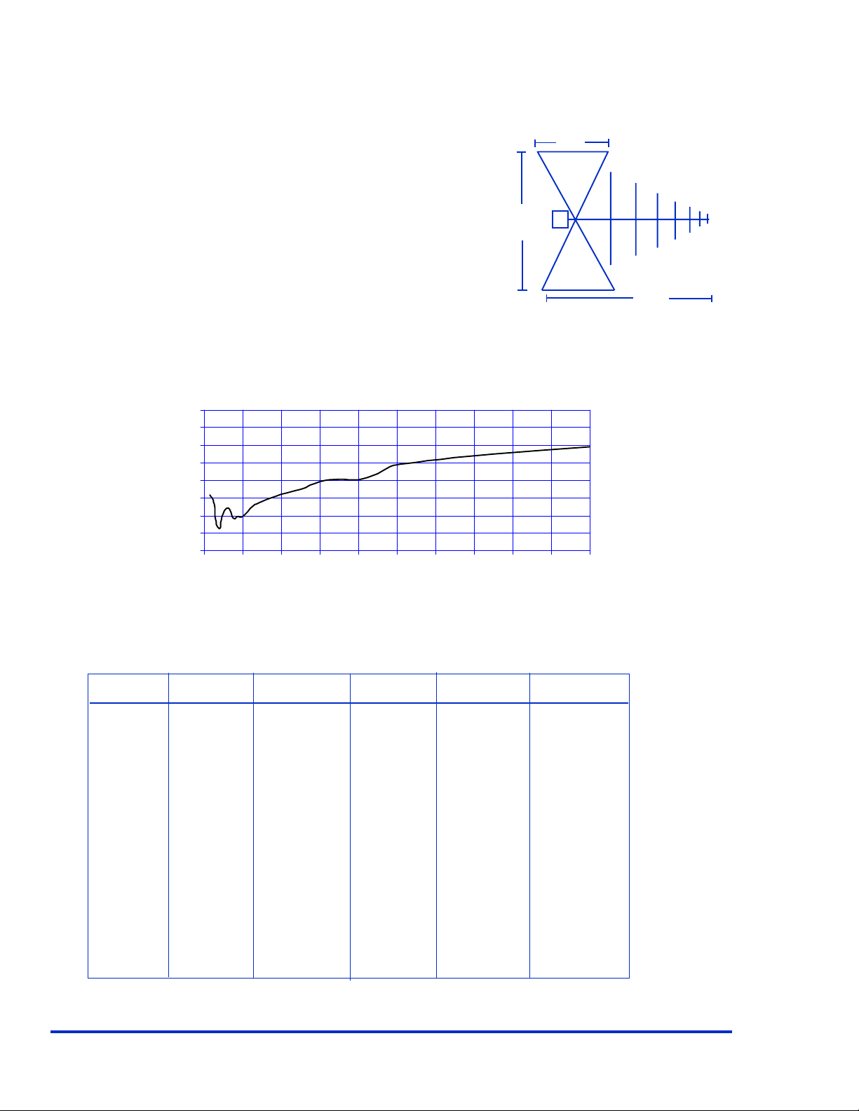
Dimensions ((L x W x H): 38 x 50 x 25 inches , 96 x 127 x 63 cm
T ypical Antenna Factors (Model A C-213 and AC-220)
40.0
35.0
30.0
25.0
20.0
15.0
Factors (dB/m)
10.0
5.0
0.0
0 200 400 600 800 1000 1200 1400 1600 1800 2000
Frequency (MHz)
25”
50”
38”
Typical Input Power Requirement in (Watts) at 1 meter antenna spacing to achieve field (V/m)
Freq. 3 V/m 10 V/m
80 0.67 29.7
90 0.70 31.2
100 0.60 26.5
125 0.55 24.5
150 0.16 7.10
175 0.17 7.46
200 0.10 4.24
250 0.09 3.83
300 0.07 2.92
400 0.04 1.90
500 0.03 1.43
Specification subject to change without notice.
All values are typical unless specified.
Com-Power Corporation 20621 Pascal Way, Lake Forest, California 92630 (949) 587 - 9800 www.com-power.com Rev 1201
Freq. 3 V/m 10 V/m
600 0.02 1.08
700 0.02 1.00
800 0.02 0.88
900 0.02 0.76
1000 0.01 0.64
1500 0.01 0.29
2000 0.01 0.25
A-8
 Loading...