

Page 1

SOLAR ELECTRONICS COMPANY
A Division of
11158 CHANDLER BLVD.
N. HOLLYWOOD, CALIFORNIA 91601
Telephone' (818) 755-1700
Fax: (818) 755-0078
E-Mail (scott@solar-emc.com
A. T. Parker lne.
)
PAGES:
DATE:
COMPANY:
COMPANY FAX: 1(858)558-6570
ATTENTION:
FROM:
REF:
COMMENT:
2
9/25/03
Advanced Test Equipment
Jim Tighe
Scott McDonald
9719-IN
calibration in 300 ohm loop
The network analyzer was set up to be a 150 ohm system by placing a 100 ohm resistor in series
with the 50 ohm generator and a 100 ohm resistor in series with the 50 ohm receiver (300 ohm
loop) and normalized. Next, the current probe, in a calibration fixture, was inserted. The signal
generator was then connected to the connector on the injection probe. A 150 ohm resistor was
placed in. shunt with one end of the fixture and a 100 ohm resistor was placed in series with the
receiver and connected to the other end of the calibration fixture completing the 300 ohm loop.
I hope this help,
Scott McDonald
Please visit our Web page
(
www.solar-eme.com
)
Page 2
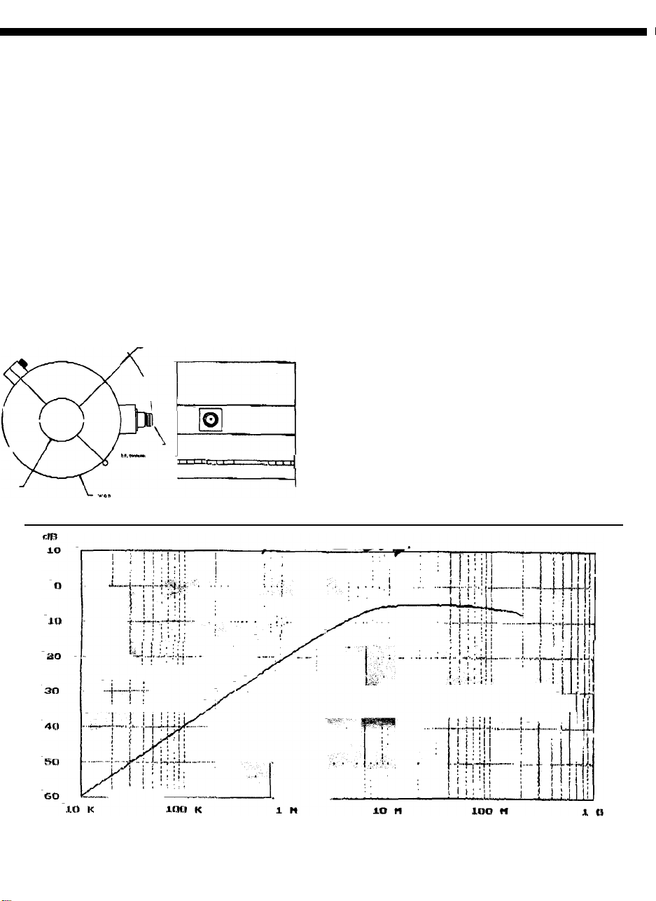
SOLAR TYPE 9719-1 N INJECTION PROBE.
Specifications:
Frequency range:
Maximum input power:
Maximum input current:
Maximum time for continuous rating at full power:
Recommended maximum temperature rise:
Maximum core temperature
Turns ratio:
nput receptacle:
I
Weight:
Fastening:
Dimensions;
10 kHz to 350 MHz
200 watts
60 Amperes
30 minutes
35 degrees C
80 degrees C
Type "N"
3,75kg (8.8 lbs,)
Thumb Screw
Female
1:1
A:
B:
C:
W:
4.25"
4.92"
1.125"
1.50"
(108.0mm)
(125.0mm)
(28.58mm)
(38.0mm)
SOLAR ELECTRONICS COMPANY
901 NORTH HIGHLAND AVENUE - HOLLYWOOD, CALIFORNIA 90038TELEPHONE (323) 462-0806 .- FAX (323) 462-3721
A DIVISION OF A. T. PARKER, Inc.
Page 3

 Loading...