

Page 1
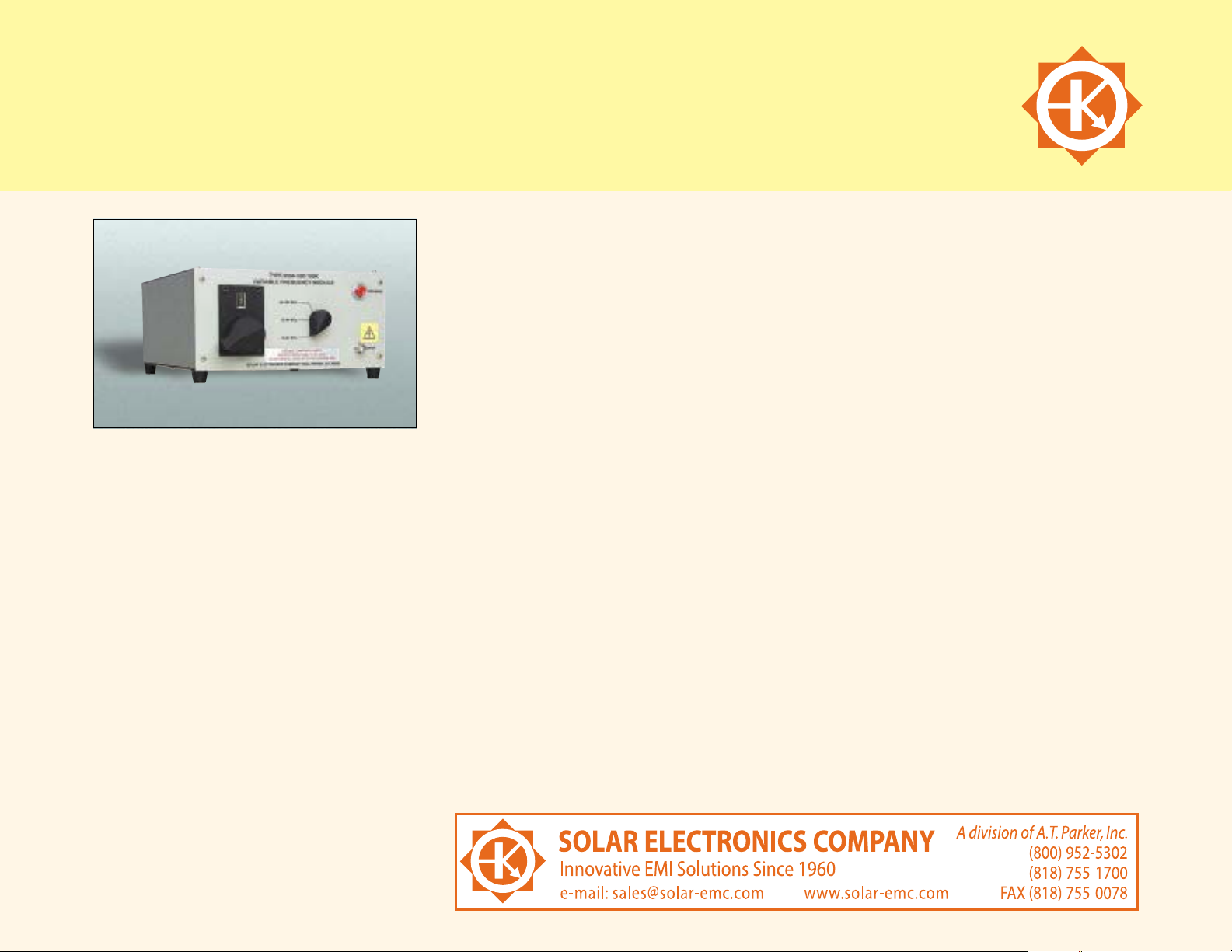
MODEL 9554-( ) VARIABLE FREQUENCY MODULES
for use with Model 9354-1 Universal Transient Generator as required by
Method CS-116, MIL-STD-461 Rev. D
After the charge voltage is adjusted to the desired
value, the damped sine wave is applied to the
load by pushing the button on the module.
USEFUL ACCESSORIES
Type 9125-1 Calibration Jig
Type 9142-1N Injection Probe
Type 9357-1 Calibration Jig
Type 9335-2 Multiple Impedance Coupling
Device
Type 9410-1 High Voltage Attenuator (The
input to the Type 9410-1 can be used for a
50 ohm coaxial load as required by MIL-STD-462D
Figure CS116-1.)
Type 9841-1 1000 Volt Termination, 50 ohm
coaxial 1 W average power. Typical input VSWR in
a 50 ohm system under 1.5 from DC to 1 GHz.
APPLICATION
Utilizing the high voltage power source in the
Model 9354-1 Universal Transient Generator,
four individual modules can be connected
to provide tuning of damped sine waves from
10 KHz to 50 MHz. A fifth module is available
which, when used in conjunction with the Model
9354-1,provides 20% frequency steps from
30 MHz to 100 MHz.
DESCRIPTION
Individual modules enable tuning of damped sine
waves in accordance with the requirement of
Method CS-116, MIL-STD-461 Rev. D. The part
number of each module indicates the frequency
range of the module. For example, P/N Type
9554-10K/100K indicates a range of 10 KHz to
100 KHz. The five modules are identified as:
Type 9554-10K/100K variable frequency module
Type 9554-100K/1M variable frequency module
Type 9554-1M/6M variable frequency module
Type 9554-6M/50M variable frequency module
Type 9754-35M/85M step frequency module
Two cables connect the module to the Model
9354-1. One cable is a single insulated wire to
carry high voltage d.c. to the module. The other
cable delivers low voltage d.c. to the module for
operation of relays.
OPERATION
The test setup for calibration of test waveform is
indicated in Figure CS116-1, page 79 of MIL-STD462D. To achieve the required injection current,
the digital display on the front panel of the Model
9354-1 can be recorded during the calibration
step for reference and repeated when the actual
test setup is in accordance with Figure CS116-3,
page 81 of MIL-STD-462D. This calibration must
be repeated at each test frequency.
The frequency of the damped sine wave is
adjusted by a tuning control on the panel of the
module. A graph showing frequency versus turns
count on the tuning control is supplied.
With the selected module connected, the charge
voltage of the module is adjusted by the AMPLITUDE control on the Model 9354-1 Universal
Transient Generator.The AMPLITUDE knob is
marked in percentage of the available charge
voltage for the module being used.
The amplitude and frequency of the damped sine
wave into the load can be determined by an
associated oscilloscope with a 50 ohm input.
13
 Loading...