

Page 1
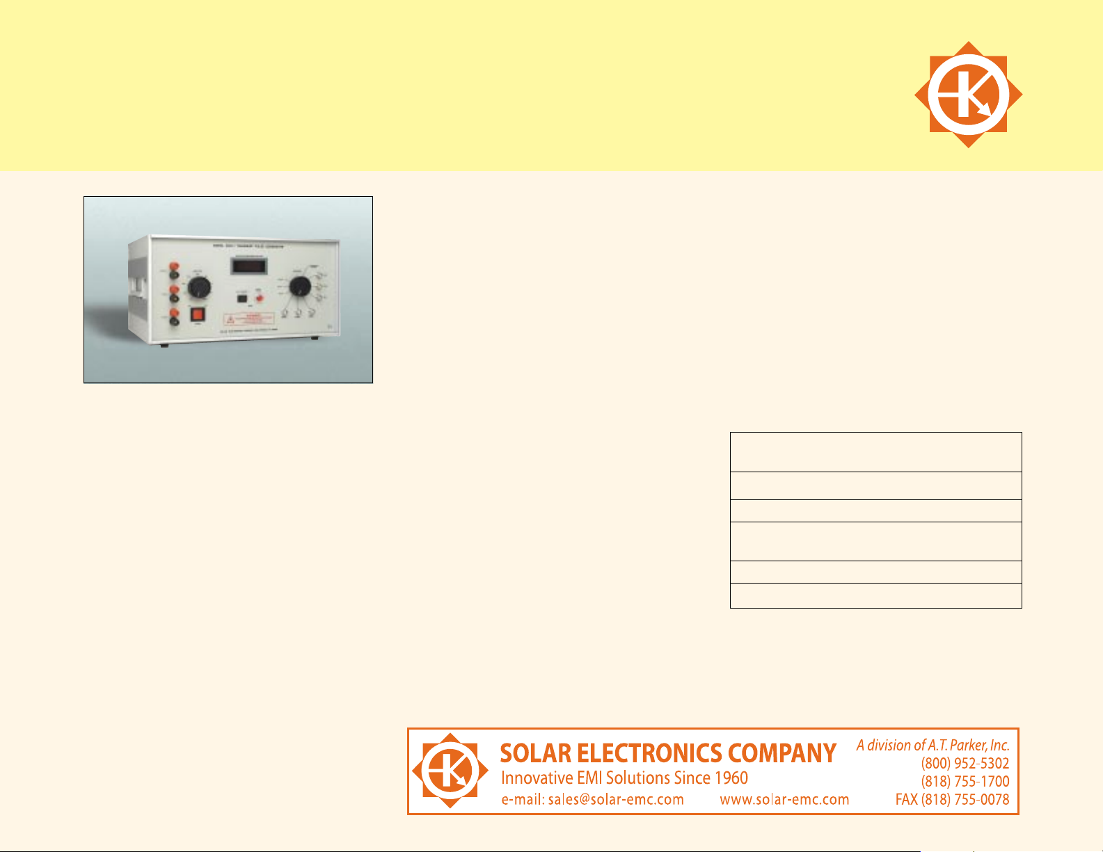
MODEL 9354-1 UNIVERSAL TRANSIENT GENERATOR
for susceptibility tests MIL-STD461C/D/E, DO-160C/D and other specifications
APPLICATION
The Model 9354-1 Universal Transient
Generator was especially designed for the
performance of a variety of pulse susceptibility
tests on subsystems and/or equipment, in
accordance with MIL-STD-461D and E, method
CS116; RTCA DO160D, section 22; MIL-STD-461C,
methods CS10 and CS11.
Through the use of many Solar accessories,
including various reactive networks and coupling
devices, as well as other commercially available
items such as loop antennas, parallel plates,
and TEM cells, the generated output may be
modified and applied to other specifications.
(Contact Solar customer service for details.)
DESCRIPTION
Model 9354-1 Universal Transient Generator
provides nine selectable waveforms, including
six damped sinusoidal pulses (10 KHz, 100 KHz,
1 MHz, 10 MHz, 30 MHz, and 100 MHz) and
three double exponential pulses (6.4 S, 70 S
and 500 S).
Auto pulsing of the sinusoidal repetition rate
is internally adjusted from 0.5 to 1.0 pulse per
second. A front panel-mounted push button can
be used to manually trigger single pulses. The
peak amplitude of the selected output pulse is
adjustable as a percentage of the charge voltage.
The six damped sinusoidal waveforms were
designed to meet the requirements of
MIL-STD-461D and E, method CS116, when
applied in accordance with the test method of
MIL-STD-462D. Continuous tunable frequencies
can be obtained by the use of the optional
variable frequency modules.
These same waveforms are applicable to the
requirements of MIL-STD-461C, methods CS10
and CS11, when applied in accordance with the
test method of MIL-STD-462, Notice 5.
The 1MHz and 10 MHz damped sinusoidal
waveforms have been extended to a peak open
circuit voltage of 3200 volts and a calculated
short circuit current of 128 amperes to meet
the requirements of RTCA DO-160D, Section 22,
Table 22-2,waveform 3.
The three double exponential pulses were
designed to meet the requirements of RTCA
DO-160D, Section 22, Tables 22-2 and 22-3.
Table 1 lists the test level that can be achieved
from the Model 9354-1.
FEATURES
Panel-mounted digital voltmeter. Monitors the
adjusted open circuit discharge voltage.
Pulse rates up to two pulses per second
maximum (factory adjusted).
Single pulse feature enables controlled
isolation of transient effects.
Output voltage adjustable from 0.1% to 100%
of selected discharge voltage.
Table 1: DO-160D Test Levels possible
from Model 9354-1
Waveform Pin Injection Cable Bundle
Injection
1 (70 S) no requirement level 1- 4
2 (6.4 S) no requirement level 1 - 4
3 (1MHz & level 1 - 5 level 1 - 4
10 MHz)
4 (70 S) level 1 - 5 level 1 - 4
5B (500 S) level 1 - 4 level 1 - 3
9
Page 2
MODEL 9354-1 UNIVERSAL TRANSIENT GENERATOR
AVAILABLE ACCESSORIES
Variable and Step Frequency Modules. Provides
tunable frequencies for injection of damped
sinusoidal wave forms from 10 KHz to 100 MHz
when used with Model 9354-1. Five individual
modules waveforms cover the entire frequency
range required by MIL-STD-461D. Detailed
information provided on separate data sheet.
Type 9335-2 Universal Coupling Device. An
inductive injection device that provides voltage
and current transfer of 1:1, 1:1.5 and 3:1 voltage
step-up (current step-down) as well as 2:1 voltage
step-down (current step-up).For maximum power
transfer, these ratios are selected by connecting
to one of the four BNC connectors. This device,
through its various connector ports, provides a
better impedance match or power transfer, higher
open circuit voltages, or higher short circuit
currents. Useable for cable current injection from
10KHz to 10 MHz. Detailed information provided
on separate data sheet.
Type 9719-1N Injection Probe. Provides the
required current leveles of MIL-STD-461D and E,
method CS116 throughout the entire frequency
range of 10 KHz to 100 MHz.
Type 9357-1 Calibration Fixture. Calibration
fixture provides a 50 ohm characteristic
impedance based on the dimensions of the
Type 9335-2 Universal Coupling Device
and Type 9719-1N Injection Probe. The fixture
maintains a low standing wave ratio from 10 KHz
to 100 MHz in a 50 ohm circuit.
Type 9142-1N Injection Probe. Used to inject
current on cables from 1 MHz to 100 MHz.
Type 9125-1 Calibration Fixture. Calibration
fixture for use with Type 9142-1N Injection
Probe.
Type 9123-1N Current Probe. Used to monitor
injected pulses. Frequency range from 10 KHz to
500 MHz.
Type 9410-1 50/50 and Type 9454-1
600/50 High Voltage Attenuators. Provides
40 dB attenuation from 10 KHz to 100 MHz.
Protects oscilloscope from high voltage damage
when verifying the output pulses of the
Model 9354-1. The Type 9454-1 provides a high
impedance to the oscilloscope for making
measurements of open circuit output pulses.
Type 6220-4 High Voltage Audio Isolation
Transformer. When connected in series with the
power lead under test, provides twice the open
circuit voltage or twice the short circuit current
for the 10 KHz and 100 MHz damped sinusoid
waves and the 6.4 S and 70 S double
exponential pulses. Capable of handling up to
4000 volts.
Type 9616-1 Injection Clamp.Provides coupling
for high voltage pulses produced by the Model
9354-1. Meets the inductive indirect injection
device requirement of MIL-STD-462, notice 5,
method CS10 and CS11. Enables injection of 70
S double exponential pulses without need for
direct connection.
SPECIFICATIONS
DAMPED SINUSOID PULSES
(NOTE: MEASUREMENT OF SHORT CIRCUIT CURRENTS ARE LIMITED BY THE XLOF THE CIRCUIT.
ALL VALUES ARE CALCULATED.)
10 KHz
Open Circuit Voltage . . . . . . . . . . . . . . . . . . . . . .30 V.
Calculated Short Circuit Current . . . . . . . . .120 A.
Source Impedance . . . . . . . . . . . . . . . . . . . . .<0.25
100 KHz
Open Circuit Voltage . . . . . . . . . . . . . . . . . . . . .300 V.
Calculated Short Circuit Current . . . . . . . . . .120 A.
Source Impedance . . . . . . . . . . . . . . . . . . . . . .<2.5
1 MHz
Open Circuit Voltage . . . . . . . . . . . . . . . . . . . .3200 V.
Calculated Short Circuit Current . . . . . . . . .128 A.
Source Impedance . . . . . . . . . . . . . . . . . . . . . .<25
10 MHz
Open Circuit Voltage . . . . . . . . . . . . . . . . . . . .3200 V.
Calculated Short Circuit Current . . . . . . . . .128 A.
Source Impedance . . . . . . . . . . . . . . . . . . . . . .<25
30 MHz
Open Circuit Voltage . . . . . . . . . . . . . . . . . . . .1000 V.
Calculated Short Circuit Current . . . . . . . . . . .20 A.
Source Impedance . . . . . . . . . . . . . . . . . . . . . .<50
100 MHz
Open Circuit Voltage . . . . . . . . . . . . . . . . . . . . .300 V.
Calculated Short Circuit Current . . . . . . . . . . . .6 A.
Source Impedance . . . . . . . . . . . . . . . . . . . . . .<50
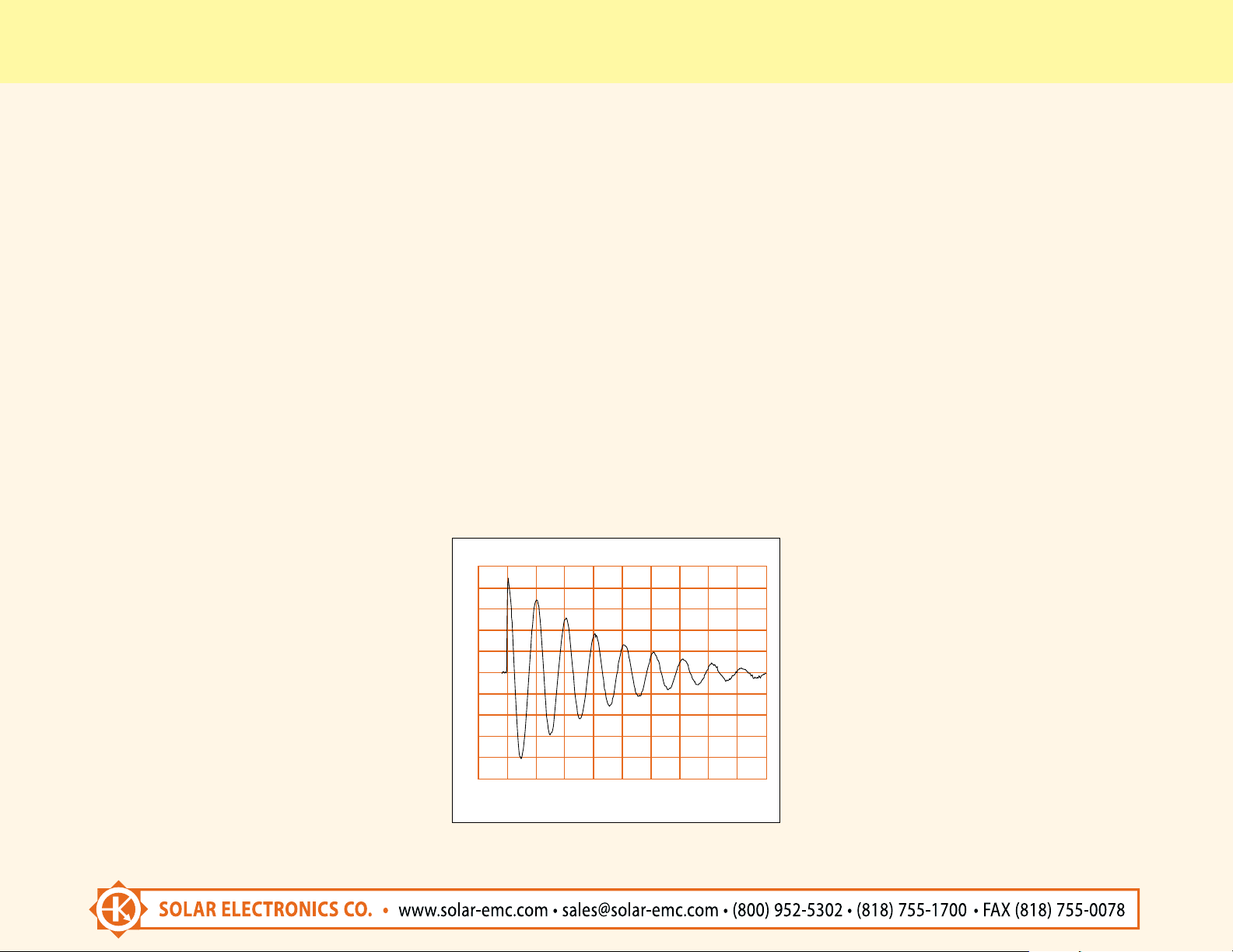
DAMPED SINUSOIDAL PULSE, (10 KHz) INTO AN OPEN CIRCUIT.
10
VOLTS
40
20
0
-20
-40
0 S
DAMPED SINUSOIDAL PULSE, 10 KHz INTO AN OPEN CIRCUIT.
200 S
400 S
600 S
800 S
Page 3

MODEL 9354-1 UNIVERSAL TRANSIENT GENERATOR
DOUBLE EXPONENTIAL PULSES
(NOTE: MEASUREMENT OF SHORT CIRCUIT CURRENTS ARE LIMITED BY THE XLOF THE CIRCUIT.
ALL VALUES ARE CALCULATED.)
6.4 S
Rise Time . . . . . . . . . . . . . . . . . . . . . . . . . . . . . .100 nS.
Open Circuit Voltage . . . . . . . . . . . . . . . . . . . .1600 V.
Calculated Short Circuit Current . . . . . . . . .800 A.
Source Impedance . . . . . . . . . . . . . . . . . . . . . .<2.0
70.0 S
Rise Time . . . . . . . . . . . . . . . . . . . . . . . . . . . . . .6.4 S.
Open Circuit Voltage . . . . . . . . . . . . . . . . . . . .1600 V.
Calculated Short Circuit Current . . . . . . . . . .800 A.
Source Impedance . . . . . . . . . . . . . . . . . . . . . .<2.0
500 S
Rise Time . . . . . . . . . . . . . . . . . . . . . . . . . . . . . . .50 S.
Open Circuit Voltage . . . . . . . . . . . . . . . . . . . .1600 V.
Calculated Short Circuit Current . . . . . . . . . .400 A.
Source Impedance . . . . . . . . . . . . . . . . . . . . . .<4.0
DIMENSIONS
Weight:55.0 lbs. (25 Kg)
Size: 17.25" (43.5 cm) wide x 8.75" (22.2 cm) high x
13" (33.0 cm) deep.
Test Configuration 1
DOUBLE EXPONENTIAL PULSE INTO AN OPEN CIRCUIT.
PROBE
PROBE
9719-1N
9719-1N
6220-4
9354-1
SCOPE
SCOPE
9354-1
11
VOLTS
3 KV
2 KV
1 KV
0
0 mS
1 mS
2 mS 3 mS
4 mS 5 mS
 Loading...