

Page 1

Agilent 8904A
Multifunction Synthesizer
dc to 600 kHz
Build complex waveforms from common signals
Page 2
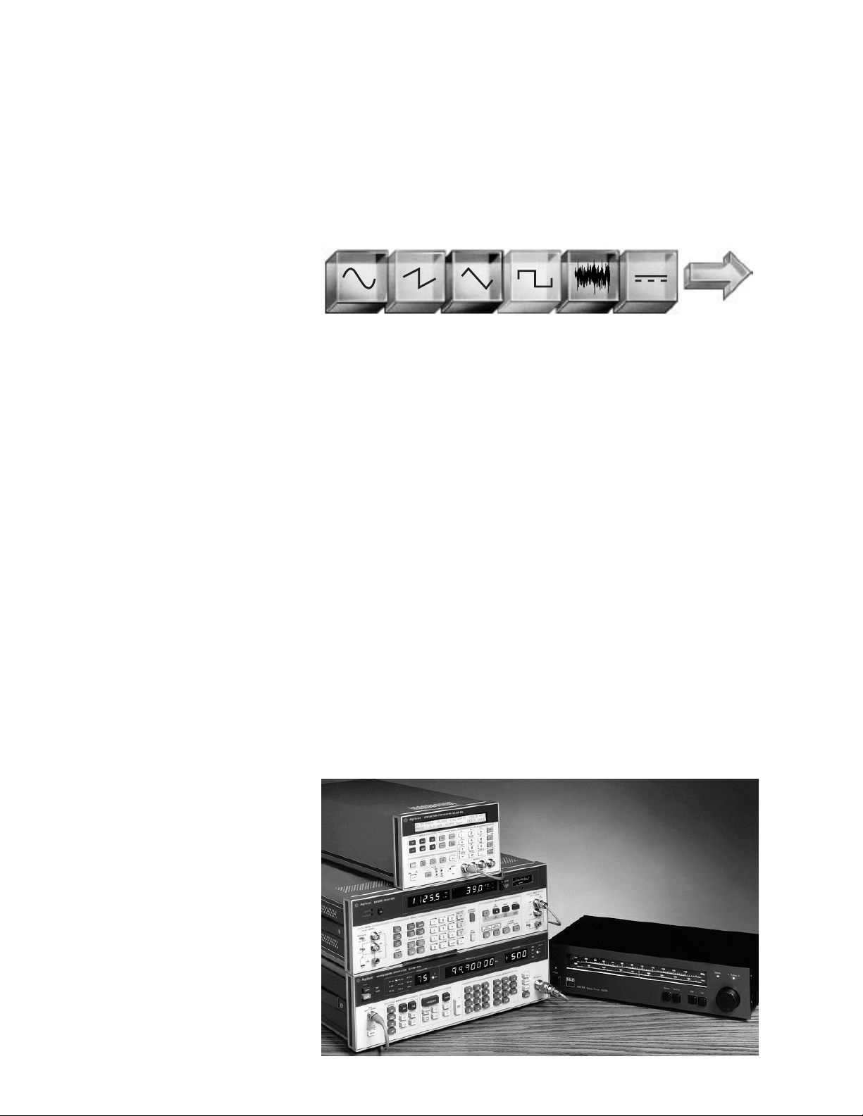
The Agilent Technologies 8904A
Multifunction Synthesizer uses the
latest VLSIC technology to create
complex signals from six fundamental
waveforms. The standard 8904A digitally synthesizes precise sine, square,
triangle, ramp, white noise, and dc
waveforms and routes these signals
to a single output. Option 001 adds
three more identical internal synthesizers (channels) which can either
modulate the first synthesizer or be
summed to the output. Frequency,
amplitude, waveform, phase, and destination can be independently set for
each synthesizer. Available modulation types for channel A include AM,
FM, F M, DSBSC, and pulse modula-
tion. Option 002 adds a second 50 Ω
output, providing a second separate
signal for two channel applications.
Option 003 adds fast hop and digital
modulation capability to the 8904A.
Option 005 allows multiple 8904As to
be phase synchronized for applications which require the use of more
than one 8904A. Option 006 changes
output 1 of the 8904A from a 50 Ω
floating output to a 600 Ω, high-power
balanced output. With this option, the
8904A can deliver 10 volts rms into a
600 Ω load from 30 Hz to over 100 kHz.
All this unique capability makes the
8904A a powerful tool for demanding
applications like VOR, ILS, FM Stereo,
and communications signaling.
. . . Begins with . . .
Function synthesizer
The Agilent 8904A Multifunction Synthesizer delivers synthesizer accuracy,
along with six waveforms in a compact,
economical package. Broad sinewave
frequency coverage from 0.1 Hz to
600 kHz with 0.1 Hz resolution make
the 8904A ideal for a number of lowfrequency applications. In addition to
sinewave generation, the 8904A has
five other standard functions: square,
triangle, ramp, dc, and Gaussian white
noise. Of these five, square, ramp, and
triangle functions are available from
0.1 Hz to 50 kHz. All waveform values
in the 8904A are DIGITALLY calculated
in real time by Agilent’s Digital Waveform Synthesis IC. The use of this chip
results in signals with very well-defined
accuracy and exact repeatability. This
means unprecedented performance at
an unexpectedly low price. Compared
with analog technologies, drift is eliminated, accuracy is improved, and the
number of required adjustments is
greatly reduced.
Modulation source
For demanding modulation requirements, where internal modulation
sources of signal generators don’t
measure up, use the Agilent 8904A
Multifunction Synthesizer. With its
digitally synthesized accuracy and
resolution, the 8904A is an ideal, yet
low cost, external modulation source
for signal generators. Besides common sinewave modulation, the functions of the 8904A can be used to create more complex modulating signals.
For example, use the 8904A to externally modulate a signal generator
with the noise function while at the
same time using internal modulation.
Using this technique accurate degradation of the modulation signal-tonoise ratio can be achieved. To accommodate applications requiring remote
operation for system use, the 8904A
comes with GPIB as a standard feature.
2
The Agilent 8904A
Multifunction Synthesizer . . .
Page 3
3
Stimulus for audio circuits
The 8904A has many characteristics
and features which make it well suited
as a stimulus for audio circuits. The
output of the 8904A is characterized
by low spurious and harmonic content.
Total harmonic distortion plus noise
(including all spurs) can be as low as
–78 dBc. With low distortion, the
8904A can be used to test many high
performance audio devices. Another
unique characteristic of the 8904A is
its exceptional level flatness. From
0.1 Hz to 100 kHz, the 8904A offers
±0.009 dB level flatness relative to
1 kHz. This state-of-the-art performance is a real plus for high performance audio test applications. Ground
loops can be one of the most difficult
problems to correct in audio tests.
The 8904A is equipped with an elec-
tronically floating, 50 Ω output ampli-
fier which makes overcoming ground
loops easy.
Two outputs
Option 002 adds a second, identical
synthesizer and floating output section
to make the 8904A TWO synthesizers
in one half-rack width instrument.
Frequency, amplitude, waveform, and
phase can be independently set for
each of the two synthesizers. The
flexibility provided by two sources is
needed in a variety of applications.
When simultaneous external modulation of a signal generator is required,
the 8904A Option 002 provides an
accurate, low-cost method of generating two independent modulating signals. Many two-input applications,
such as differential amplifier testing,
can benefit from the ability of the
8904A Option 002 to generate two
independent test signals at the same
time. Modern ATE systems designed
to test complex systems or products
require a number of sources to fully
stimulate the device being tested. In
these cases one or more 8904A Option
002 Multifunction Synthesizers can be
used to provide multiple test signals.
Two instruments provide four synthesizers and occupy only one 5.25-inch
full rack space.
Phase offset
Although both synthesizers are independent, the relative phase between
the two outputs can be precisely controlled. Either synthesizer can be varied in phase from 0 degrees to 359.9
degrees with a resolution of 0.1 degree.
Direct digital synthesis ensures accurate, repeatable phase differentials.
Phase accuracy between outputs is
specified to be better than ±0.1 degree
or 30 ns (whichever is greater) up to
100 kHz. Testing phase detectors, servo
systems, shaft encoders, sonar, and
other phase-sensitive two-port devices
is easy and accurate with the 8904A
Option 002. One unique application of
the 8904A’s phase capabilities is in
driving balanced loads or lines. By
operating the two synthesizers 180
degrees out of phase, the 8904A can
function as a balanced source with
much higher voltage output capability.
In this configuration, the 8904A can
deliver +23.8 dBm (12 volts rms) into
a balanced 600 Ω load with a 100 Ω
effective source impedance.
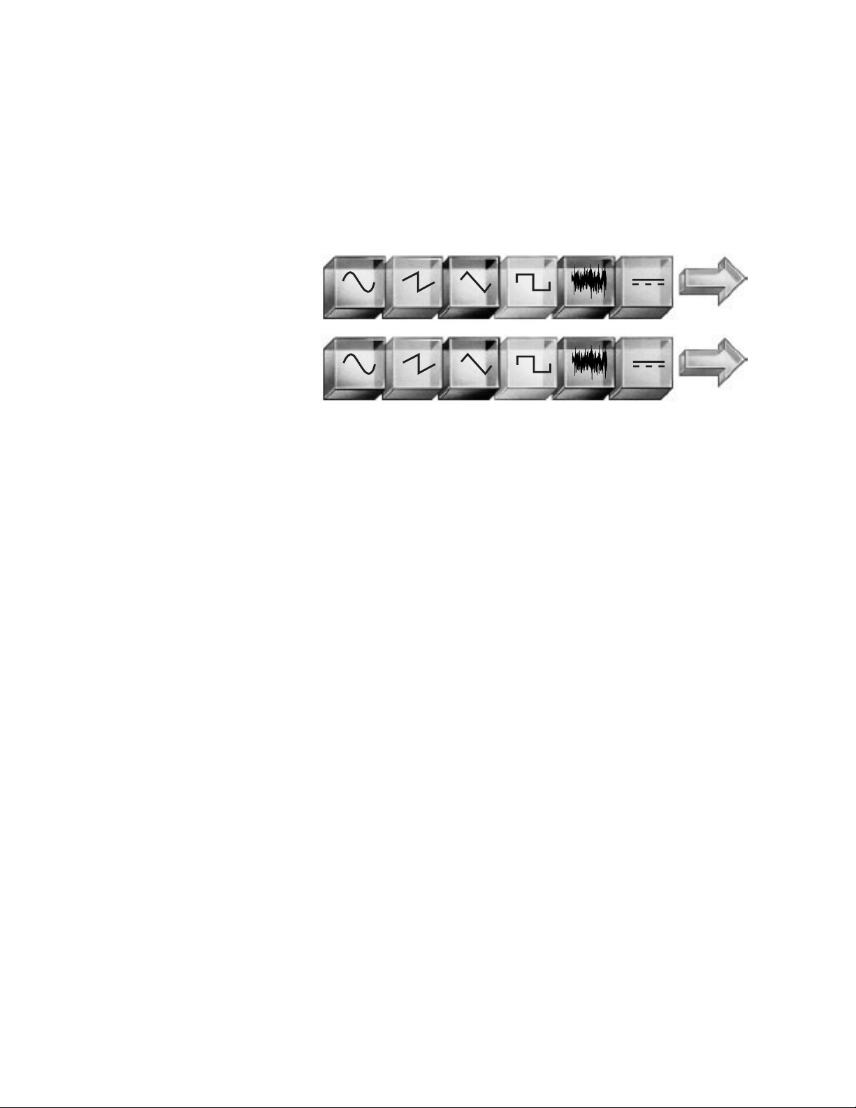
. . . And . . .
Then add another . . .
Page 4

Complex signal generation
By adding three more internal synthesizers (two with Option 002) which can
modulate or be summed with synthesizer A (channel A), Option 001 is the
key to complex signal generation for
the Agilent 8904A Multifunction Synthesizer. All four internal synthesizers
can be set to generate different waveforms, frequencies, amplitudes, and
phases at the same time. These signals
can then be DIGITALLY summed before
routing to the output. If Option 002 is
present, channels may be routed to
either of the two outputs. In addition
to summing, Option 001 allows channels B, C, and D to be used as modulation sources for channel A. The allowable modulation types for channel A
are: AM, FM, fM, DSBSC (Double
Sideband Suppressed Carrier), and
pulse modulation. Channels B, C, and
D can be used to generate up to three
independent forms of modulation at
the same time, or can be summed prior
to channel A modulation. Using summation and modulation, the 8904A
Option 001 can generate many complex
waveforms.
4
Then add two more . . . and sum . . . and modulate . . .
AM FM F M DSB Pulse
Output 1
Output 2
With Option 002, two units provide four
independent outputs in one full width rack
space.
CHANNEL B
CHANNEL C
CHANNEL D
S
Option 001 adds three internal synthesizers
(two in conjunction with Option 002) which
can modulate or be summed with channel A.
CHANNEL A
Page 5

5
VOR/ILS
VOR (VHF Omni Range) signals are
used by modern aircraft for navigation. To create accurate VOR composite signals, a generator must have
precise frequency modulation and
extremely accurate phase settability.
Agilent 8904A Option 001 meets these
needs easily with mathematically calculated frequency modulation and the
repeatability of digital phase offset
control. For VOR, channel B is used
to frequency modulate channel A,
while channel C is summed with the
modulated channel A. The bearing
angle can then be changed by altering
the relative phase of channel C. The
minimum bearing angle resolution is
0.1 degree. Since the entire VOR composite waveform is “calculated” in real
time by the Digital Waveform Synthesis
IC, the 8904A Option 001 can deliver
typical bearing accuracy on the order
of ±0.05 degrees. This state-of-the-art
performance is repeatable and drift
free unlike older technology analog VOR
generators. ILS (Instrument Landing
System) composite signals can also be
generated with digital accuracy with
the 8904A Option 001.
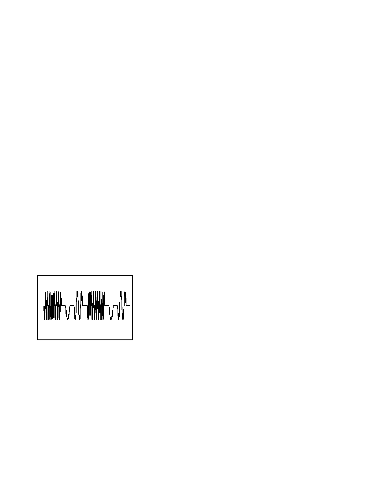
Audio testing
With Option 001, the 8904A can generate many different types of test signals used in audio applications. By
summing or modulating with the four
internal channels, the 8904A can generate intermodulation test signals
which conform to international standards. CCIF twin-tone, DIN, and
SMPTE intermodulation test signals
can be created with the 8904A. Typical
residual intermodulation distortion is
less than –70 dB. With independent
control of all four internal synthesizers, almost any type of IM test signal
can be generated. Another complex
signal often used to test amplifier
power reserves is the IHF Dynamic
Headroom test signal. The 8904A can
generate this signal with synthesizer
precision, low distortion, and exact
timing. In fact, any sinewave burst
signal can be created which will be
glitch free with phase continuous
transitions within the frequency resolution of the 8904A (0.1 Hz). Another
useful signal is a phase-continuous
linear sweep. By using a ramp waveform to frequency modulate channel
A, a linear phase continuous sweep
can be created. Sweep time can be
varied from 10 seconds (ramp at 0.1 Hz)
to 20 microseconds (ramp at 50 kHz).
Special functions can be set which will
reverse the modulating ramp waveform
to produce sweeps which change the
sweep direction.
FM stereo mode
In conjunction with an RF signal generator, the 8904A Option 001 can generate the signals required to test commercial FM broadcast stereo receivers.
The FM stereo mode included with
Option 001 transforms the 8904A into
a dedicated FM stereo encoder. Single
keystrokes control the audio test tone
frequency, composite signal level, test
signal mode, pilot on/off, and pilot
level in terms of % of composite level.
Test signal modes include Left=Right,
Left=– Right, Left Only, and Right Only.
The pilot tone amplitude, frequency
and phase, as well as subcarrier frequency are fully adjustable. Audio
test tone frequency can be set from
20 Hz to 15 kHz in 0.1 Hz increments.
Three pre-emphasis curves ensure
compliance with all international standards: 25 µsec, 50 µsec, and 75 µsec.
Digital synthesis combined with superb
analog performance yields typical
stereo separation of greater than 65 dB
over the full 20 Hz to 15 kHz audio
bandwidth. The digital nature of the
stereo test signals generated by the
8904A eliminates such signal by-products as subcarrier leakage and pilot
tone/subcarrier phase error found in
analog stereo encoders.
. . . And you get complex signal generation . . .
Page 6
6
Communication signaling
In addition to the extra channels,
Option 001 also adds four sequence
modes to the 8904A: tone sequence
mode, DTMF sequence mode, digital
sequence mode, and Hop Ram sequence
mode. These modes make the 8904A a
powerful tool for generating sequences
used in communications signaling.
Tone sequence mode allows entry of
16 unique sine wave tones, each with
an “on-time” and “off-time.” From
these 16 tones, sequences can be built
up to a length of 750 tones. The minimum on and off time duration is 800 µ s
with 10 µs resolution, while the maximum value is 655.35 ms. Timing accuracy is better than ±20 µ s. When no offtime is specified, tone sequence mode
will switch to the next tone frequency
in a phase continuous manner without
discontinuities.
DTMF (Dual Tone Multi Frequency)
mode allows generation of sequences
up to 750 telephone type signals in
length. In DTMF mode, the 8904A can
generate the 16 standard frequency
pairs as defined by Bell Telephone (Bell
technical reference publication No.
48005). Minimum timing periods for
DTMF are 1 ms, with 10 µs resolution.
Digital sequence mode can generate
digital bit streams up to 3,000 bits in
length. Minimum period in the digital
mode is 100 µs with 10 µ s resolution.
On and off “levels” in the digital mode
can be set to any value for simulating
different logic families and asserted
“high” or asserted “low” logic conventions. For ease of entry, data may be
entered in binary, octal, or hexadecimal formats. All three modes contain
extensive sequence-editing features,
and three control modes: single sequence, continuously repeat sequence,
and manual step-through sequence.
Hop Ram sequence mode offers a mix
of the capabilities of the tone and digital sequence modes. This mode allows
entry of 16 signal states, each with an
associated amplitude, frequency, and
phase value. Sequences of up to 750
tones can be built if all 16 states are
used, or up to 3,000 tones if only two
of the states are used. A unique burst
function allows the pattern to be repeated a specified number of times
from 1 to 127. Unlike the other sequence modes, Hop Ram sequence
mode allows you to use any of the six
standard waveforms available in the
8904A: sine, square, ramp, triangle, dc
or white Gaussian noise. Instead of
selecting the timing in terms of milliseconds, Hop Ram sequence mode sets
timing in terms of frequency. This
allows the generation of patterns
which have precise baud rates such
as 1200, 2400, 4800, or 9600.
Page 7

AM FM F M DSB Pulse
Output 1
Output 2
CHANNEL B
CHANNEL C
CHANNEL D
S
External . Freq Phase Amp
Timing
7
. . . Fast hop
Option 003 adds the ability to hop the
8904A in frequency, phase, and/or
amplitude. Up to 16 frequency/phase/
amplitude states can be entered into
the “Hop Ram” memory. To hop, an
external device must address the fourbit TTL-level address bus provided on
the digital port connector on the rear
panel. As the address supplied to the
bus is varied, the 8904A will hop to
the frequency/phase/amplitude state
that corresponds to that address of the
Hop Ram memory. Fast hop can only
be performed on channel A. Phase
continuous frequency switching can
be done in as little as 8 µs. Since the
signals are digitally created, there is no
settling time like traditional PLL synthesizers. Only the cycle time of the
Digital Waveform Synthesis IC determines the switching speed. Control
functions allow you to enable or disable
any one of the three hop parameters.
For example, phase and amplitude hop
can be disabled to produce only frequency hopping without having to
remove the phase and amplitude hop
data from the Hop Ram. If Option 001
and 003 are installed, the other three
channels can be used while hopping.
Channel B, for example, could be set to
phase modulate channel A with noise
while channel A is hopping. This setup
allows controlled amounts of “phase
noise” to be added to the hopping signal.
. . . Digital modulation
One application for Option 003 is the
creation of digital modulation formats.
By hopping frequency, FSK and other
frequency switching type modulation
formats with up to 16 frequencies can
be generated. BPSK, QPSK, and other
phase shifting formats can be made by
hopping just phase. With a combination of amplitude and phase hopping,
the 8904A Option 003 can generate
QAM signals with up to 16 phase
amplitude states. The digital data
must be supplied to the digital control port in a four-bit wide parallel
word to control the timing.
Add external timing control to get . . .
Option 003 adds external
timing control for fast hop
or digital modulation
CHANNEL A
Page 8

8
. . . Phase synchronization
With Option 005, multiple 8904As can
be phase synchronized to provide more
than two channels of phase related
outputs. In the synchronous mode,
one unit is specified to be the “master”
and all others are designated “slaves.”
Two signals from the master unit (sync
clock and phase reset) are routed to
external power splitters which divide
the signals to the slave units. When a
phase reset command is issued from
the master, via the front panel or GPIB,
all units reset to their specified phase
relationships. In this mode all connected units are phase locked and
will not drift relative to each other.
Whenever the frequency, destination,
or angle modulation amplitude are
changed on any of the units, a phase
reset must be issued on the master
unit to restore proper phase. In the
synchronous mode, the phase accuracy
from unit to unit is specified as an
additional 30 ns error for frequencies
from 0.1 Hz to 100 kHz. This yields a
total specification of the larger of
±0.1 degree or 60 nsec for the same
frequency range. Using low-loss power
splitters, up to eight units can be synchronized for a total of 16 phase
related outputs if the units have
Option 002. If more signals are desired,
amplifiers can be inserted before the
power splitters to increase the number
of synchronized units. Because the
extra cables required for synchronous
operation use the mounting holes
normally reserved for rear panel outputs, Option 004 (rear panel outputs)
cannot be ordered with Option 005.
Option 005 solves many tough testing
problems by providing a high performance yet low cost solution to generating many phase related signals. For
example, testing three phase power
line devices requires the generation
of three voltage and three current
waveforms which are phase related.
With Option 005, three 8904As with
Option 002 and 005 can be used to
generate the required signals. Acoustics
and sonar work also require large
numbers of phase related signals. With
Option 005, the 8904A can be used to
provide a cost effective solution for
these demanding applications.
Or add 600 Ω balanced output
Option 006 replaces the standard 50 Ω
electronic floating output (output one
only) with a transformer coupled 600 Ω
output, This balanced, fully floating
output delivers higher power into
600 Ω loads than the standard 50 Ω
output. The maximum signal level is a
full 10 volts rms into a 600 Ω load (20
volts rms open circuit). The Option 006
output is specified for sinewaves only
and covers the frequency range of
30 Hz to 100 kHz.
Output frequencies above 100 kHz are
available up to 200 kHz with a typical
rolloff of –4 dB at 200 kHz. Option 006
is ideal for applications requiring true
balanced operation or the higher signal
levels commonly required in 600 Ω
audio systems. Because of the bandlimited nature of a transformer coupled output, Option 006 cannot pass dc
or low frequency signals, and causes
waveform distortion when passing
square or ramp waveforms. The transformer adds little distortion above
300 Hz preserving the excellent spectral purity of the standard 8904A. The
Option 006 output also has degraded
phase linearity compared to the excellent phase linearity of the standard
50 Ω output. Option 004, rear panel
outputs is not available when Option
006 is ordered.
Phase synchronization or add 600 Ω output
8904A Master
8904A Slaves
Phase Reset Sync Clock
Sync Clock Output
Phase Reset Output
Phase Reset In
Sync Clock In
Phase Reset In
Sync Clock In
Phase Reset In
Sync Clock In
Phase Reset In
Sync Clock In
Low-loss power splitters*
Page 9
9
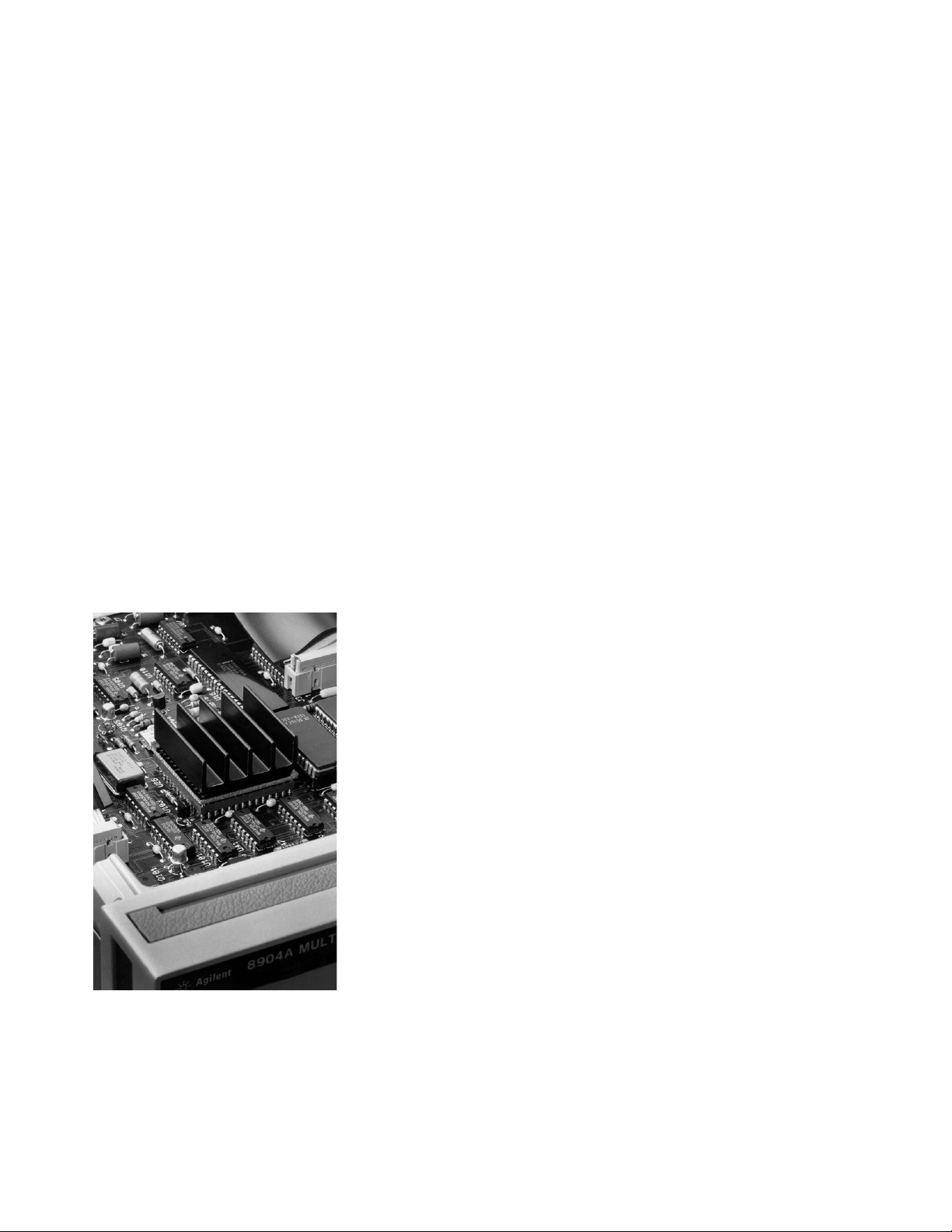
Agilent digital technology:
Unparalleled performance at an
unprecedented price
The Agilent 8904A’s Digital Waveform
Synthesis IC uses Agilent’s proprietary CMOS high-density VLSI
process. With 100,000 transistors,
this IC realizes four complete waveform synthesizers, plus a host of support functions, on a single chip. The
Digital Waveform Synthesis IC allows
the 8904A to generate complex waveforms with accuracy and repeatability
not found in traditional analog function generators or multi-phase-lockloop synthesizers. In addition, drift
and power consumption are reduced
while reliability is increased (over
400 MSI TTL chips would be required
to emulate the function of the Digital
Waveform Synthesis IC).
Abbreviated specifications
Frequency range
Sine wave: 0.1 Hz to 600 kHz
Square, triangle, ramp: 0.1 Hz to 50 kHz
AC amplitude
Range: 0 to 10V
p-p
into a 50 Ω load
Accuracy (sine wave): 1%, 0.1 Hz to 100 kHz
Flatness (>630 mV
p-p
, 1 kHz reference): ±0.009 dB, 0.1 Hz to 100 kHz
DC amplitude
Range: 0 to ±10V open circuit
THD+N (amplitude >50 mV rms, 80 kHz BW, sine wave)
– 66 dBc rms, 20 Hz to 20 kHz (30 kHz BW to 7.5 kHz)
Phase (sine wave)
Range: 0 degrees to 359.9 degrees
Gaussian noise
Spectral characteristic: Equal energy per unit bandwidth (“white”)
Option 001 specifications
Modulation (with Option 001)
Modulation for channel A ONLY, and specified for sine wave carrier and modulation.
External modulation is NOT possible.
Modulation types: AM, FM, fM, Pulse, and DSBSC
Summation (with Option 001)
Two, three, or four channels may be summed into a single output. Two or three channels
may be summed for modulation of channel A.
Sequence
Sequence modes: Tone, DTMF, and Digital sequence modes
Sequence length: 250 tones for Tone and DTMF modes; 1,000 bits for Digital mode
Timing resolution: 10 µs
Page 10

10
Backlit liquid crystal display presents all information in easy-to-understand
alphanumeric screens.
Tone, DTMF, Digital, and
Hop Ram sequence modes
available with Option 001
are ideal for generating signalling sequences used in
communication systems.
Softkeys provide simple
control of operating modes
and sequence functions.
Step through all display
screens with NEXT/LAST
keys.
All waveforms, phase offsets, frequencies, fine level
settings, and modulation
types are created by direct
digital synthesis which yields
outstanding accuracy and
repeatability.
Full GPIB* control for ATE
and automated production
test.
* GPIB: Not just IEEE-488, but the hard-
ware, documentation and support that
delivers the shortest path ot a measurement system.
Six standard digitally created
waveforms: sine, ramp, triangle, square, white Gaussian
noise, and dc. Calibration
quality AM, FM, fM, DSBSC,
and Pulse Modulation on
channel A.
Thirty-five storage registers
save data for a given configuration, making repetitive tasks easy.
Keypad for entering parameters and signalling
sequences.
One electronic floating 50 Ω
output is standard. Option
002 adds a second identical
50 Ω output; Option 006
converts output 1 into a
high power 600 Ω balanced
output (30 Hz to 100 kHz).
Front panel features
Page 11

11
GPIB implementation
includes powerful querry
modes to determine instrument settings.
Digital port provides zerocrossing pulse and polarity
squarewave outputs for all
four internal channels.
With Option 001, a TTL-level
line on the digital port can
be sued to start Tone, DTMF,
Digital, or Hop Ram
sequences.
Option 003 adds the capability to fast hop frequency,
phase, and amplitude by addressing the four-bit address
bus on the digital port.
Rear panel features
Page 12

Agilent Technologies’ Test and Measurement
Support, Services, and Assistance
Agilent Technologies aims to maximize
the value you receive, while minimizing
your risk and problems. We strive to
ensure that you get the test and measurement capabilities you paid for and obtain
the support you need. Our extensive support resources and services can help you
choose the right Agilent products for your
applications and apply them successfully.
Every instrument and system we sell has
a global warranty. Support is available
for at least five years beyond the production life of the product. Two concepts
underlie Agilent’s overall support policy:
“Our Promise” and “Your Advantage.”
Our Promise
“Our Promise” means your Agilent test
and measurement equipment will meet its
advertised performance and functionality.
When you are choosing new equipment,
we will help you with product information, including realistic performance specifications and practical recommendations
from experienced test engineers. When
you use Agilent equipment, we can verify
that it works properly, help with product
operation, and provide basic measurement
assistance for the use of specified capabilities, at no extra cost upon request. Many
self-help tools are available.
Your Advantage
“Your Advantage” means that Agilent
offers a wide range of additional expert
test and measurement services, which you
can purchase according to your unique
technical and business needs. Solve problems efficiently and gain a competitive edge
by contracting with us for calibration, extracost upgrades, out-of-warranty repairs, and
on-site education and training, as well
as design, system integration, project management, and other professional services.
Experienced Agilent engineers and technicians worldwide can help you maximize
your productivity, optimize the return on
investment of your Agilent instruments and
systems, and obtain dependable measurement accuracy for the life of those products.
By internet, phone, or fax, get assistance
with all your test and measurement needs.
Online Assistance
www.agilent.com/find/assist
Phone or Fax
United States:
(tel) 1 800 452 4844
Canada:
(tel) 1 877 894 4414
(fax) (905) 206 4120
Europe:
(tel) (31 20) 547 2323
(fax) (31 20) 547 2390
Japan:
(tel) (81) 426 56 7832
(fax) (81) 426 56 7840
Latin America:
(tel) (305) 269 7500
(fax) (305) 269 7599
Australia:
(tel) 1 800 629 485
(fax) (61 3) 9210 5947
New Zealand:
(tel) 0 800 738 378
(fax) (64 4) 495 8950
Asia Pacific:
(tel) (852) 3197 7777
(fax) (852) 2506 9284
Product specifications and descriptions in this
document subject to change without notice.
Copyright © 1989, 2000 Agilent Technologies
Printed in U.S.A. 9/00
5965-9457E
 Loading...