

Page 1
Personal and Area Monitors
Previous Next
T.O.C.
///////////
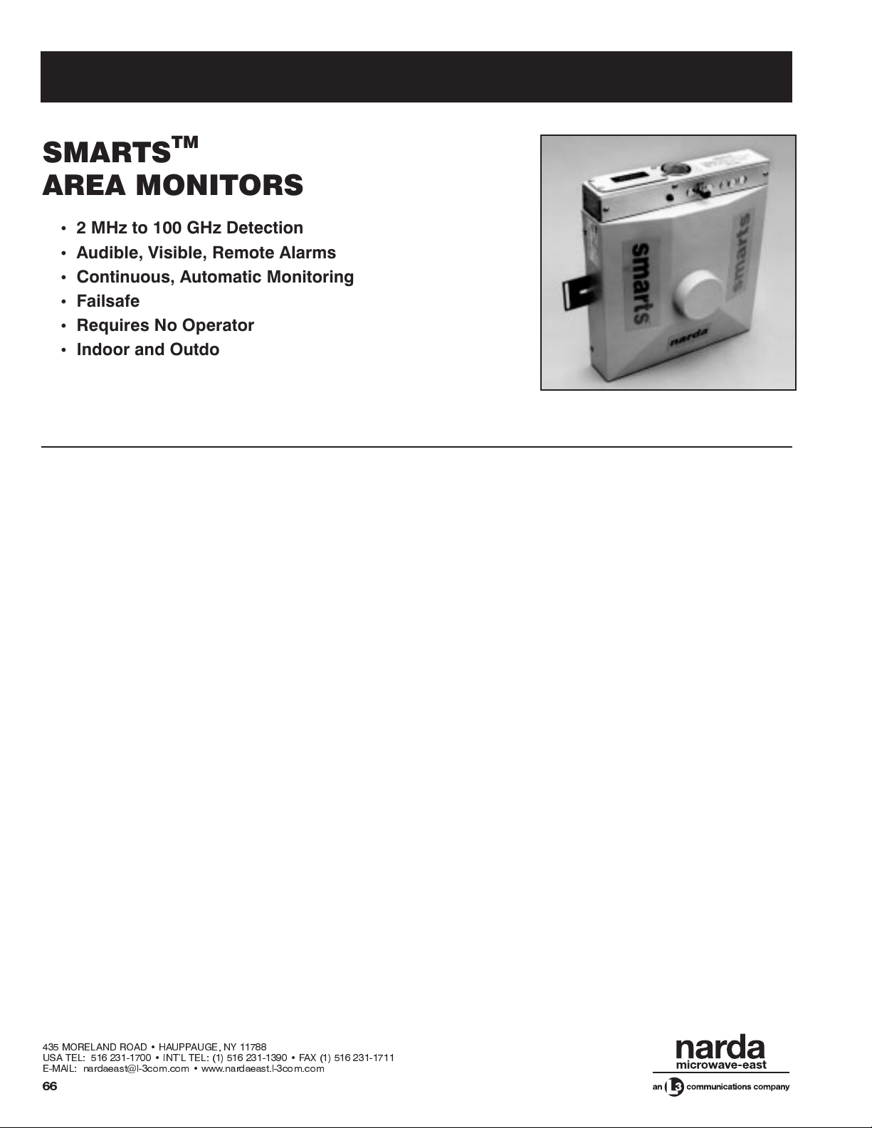
SMARTS
TM
AREA MONITORS
2 MHz to 100 GHz Detection
•
Audible, Visible, Remote Alarms
•
Continuous, Automatic Monitoring
•
Failsafe
•
Requires No Operator
•
Indoor and Outdoor Models
•
DESCRIPTION
Narda’s SMARTS family of area monitors provides continuous detection of RF radiation within a specific area.
Models are available to cover any frequency between
2 MHz and 100 GHz. These monitors represent a major
advance in safety monitoring programs for non-ionizing
radiation. In the past, a safety program was limited to performing periodic surveys of a particular system or area,
which meant anacute failure could go undetected until the
next survey was performed. And since all major international safety standards set limits for average exposure
level over a few minutes, the use of survey instruments
alone meant a hazardous condition could exist for days,
weeks, or even months. With the SMARTS, potentially
hazardous areas can be continuously monitored to help
insure a hazard-free environment as well as compliance
with industry and government standards.
Four models cover wide frequency bands from 2 MHz to
100 GHz. Model 8810 covers the 2 to 30 MHz HF band,
Model 8815 operates from10 to 500 MHz,and Model 8820
monitors frequencies between 500 MHz and 18 GHz. The
ultra broadband Model 8825B covers 500 MHz to 100
GHz.
Each model features a unique design for accurate detection in a specific environment. At low frequencies, such as
those around HF antennas and metallic shelters, the electric field component is typically greatly distorted. Therefore, the Model 8810 (2 to 30 MHz) monitors the magnetic
field which is more consistent in these environments. The
standards from Australia, Germany, the U.K. and the U.S.
all vary permissible exposure levels by 20 dB over these
frequencies. The Model 8810’s frequency curve has a
shape very similar to these standards. Its alarm threshold
is set to approximately one tenth of the exposure limits to
provide coverage over an area of several square meters.
The Model 8815 (10 to 500 MHz) utilizes what has been
termed “transitional” monitoring. At frequencies below approximately 200 MHz, it responds to the magnetic field
component and it transitions to electric field detection at
frequencies above 200 MHz.
Model 8820 (500 MHz to 18 GHz) and Model 8825B
(500 MHz to 100 GHz) use broadband thermocouple
detectors to monitor the electric field. Both models
sound an alarm only when the average power level is exceeded and are ideal for use with microwave systems
where pulse modulation is normally employed.
SMARTS monitors are available in a totally nonmetallic,
weatherproof enclosure for outdoor mounting. This enclosure will protect the SMARTS from dust, rain, or heavy seas.
435 MORELAND ROAD HAUPPAUGE, NY 11788
USA TEL: 516 231-1700 INTL TEL: (1) 516 231-1390 FAX (1) 516 231-1711
E-MAIL: nardaeast@l-3com.com www.nardaeast.l-3com.com
66
Page 2
///////////
Previous Next
T.O.C.
OPERATION
Indoor SMARTS
Personal and Area Monitors
Outdoor SMARTS
SMARTS monitors operate like common household
smoke detectors. When operating normally, the alarm
LED will flash approximately every 40 seconds. If the main
battery needs to be replaced, the flash will be accompanied by a “chirp.” When the SMARTS detects radiation at
its preset alarm threshold or higher, a continuous audible
and visual alarm is generated. During this alarm period an
electronic signal is provided at theSTATUS jack (J1) to activate various user-supplied remote circuitry. If the main
battery drops below critical levels, or if the detection elements should fail, the system will remain in the alarm
mode until the problem is corrected. If the main battery
should fail completely there will still be a voltage at the J1
produced by a backup battery circuit.
Operation can be verified at any time by depressing the
TEST button which activates a full system test. In situations where standard operating procedure produces RF
or microwave power in excess of the threshold and exposure to people is possible (e.g., inan anechoic chamber or
on the deck of a ship), the Model 8808 Personnel Sensor
can be used. This sensor will disable the SMARTS alarm
(via the J2 ENABLE jack) unless personnel and high
power radiation are both present.
Since standard visual and audio signals would be masked
by the weatherproof enclosure, outdoor SMARTS models
supply information to a remote location via a weatherproof, multi-pin, MIL-type connector (J101). Normal or
alarm STATUS information iscontinuously available at this
remote location. Also operated by remote control are the
ENABLE jack (J2) and the TEST function. Outdoor
SMARTS models operate from an external low voltage,
very low current supply brought in through the same connector. This separate DC source allows operation over a
broader temperature range.
The comprehensive SMARTS family of area monitors
should be part of every safety program involved with high
power RF or microwave energy. Other options or configurations, such as different alarm thresholds or calibration
frequencies, can be provided. Consultthe factory for details.
USA TEL: 516 231-1700 INTL TEL: (1) 516 231-1390 FAX (1) 516 231-1711
E-MAIL: nardaeast@l-3com.com www.nardaeast.l-3com.com
435 MORELAND ROAD HAUPPAUGE, NY 11788
67
Page 3

Personal and Area Monitors
Previous Next
T.O.C.
SPECIFICATIONS FOR INDOOR MODELS
///////////
MODEL No.
Frequency Range
Frequency Sensitivity
Alarm Threshold
Overload
CW
Peak
3 dB Intercept Angle
Temperature
Operating
Non-operating
Batteries
Weight (approx)
CalibrationFrequencies
Accessories Supplied
Notes:
a
Peak to peak. The threshold can be factory set to provide optimum performance over a specific band of interest.
b
The alarm threshold is proportionate to IEEE C95.1-1991 Standard and varies over the 2 to 30 MHz band. The threshold is 0.9% of
the H field Maximum Permissable Exposure (MPE) from 3 to 30 MHz and equal to 10% of the E field MPE from 2 to 30 Mhz.
(Controlled Environments)
c
The 3 dB intercept angle is >180°with the E field tangential to the mounting plane and >165°with the E field perpendicular to the
mounting plane.
d
The rated life is two years. It is recommended that this battery be replaced annually during calibration.
e
The fail-safe battery has a rated life of 5 to 10 years. It is recommended that it be checked annually during calibration and replaced
every three years.
f
Other calibration frequencies available for narrow band applications. Contact the factory.
Circuit
Fail-safe
d
e
f
8810 8815 8820 8825B
2 to 30 MHz 10 to 500 MHz 0.5 to 18 GHz 0.5 to 100 GHz
±1.5 dB
10 % of Standard
°
>180
2, 3, 10 and 30 MHz
b
60 mW/cm
60 W/cm
a
±
2.0 dB
0.1 mW/cm
2
2
>180
10, 30, 100, 300,
400 and 500 MHz
Operation Manual, J1 and J2 Mating Connectors
2
°
-10
°
C to +55°C
-40
°
Cto+75°C
9V lithium (supplied)
3V lithium (supplied)
24 oz. (0.7 kg)
3.0 dB
1.0 mW/cm
c
>180
°
8.2fGHz 8.2fGHz
2
300 mW/cm
100 W/cm
4.5 dBa0.5 - 50 GHz
6.0 dB
a
0.5 mW/cm
2
2
0.5 - 100 GHz
2
c
>180
°
ALARM OPERATION CONTROL INPUT
CONDITION
Normal Operation
Low Battery
Test Button Depressed
Alarm
Main Battery Failure
Sensor Failure
AUDIBLE &
VISUAL INDICATIONS
Light flashes every 40 sec. Low
Alarm chirps, light flashes Low
Steady sound and light High
Steady sound and light High
No sound or light High
Steady sound and light High
435 MORELAND ROAD HAUPPAUGE, NY 11788
USA TEL: 516 231-1700 INTL TEL: (1) 516 231-1390 FAX (1) 516 231-1711
E-MAIL: nardaeast@l-3com.com www.nardaeast.l-3com.com
J1
OUTPUT
68
1
CONDITION J2 INPUT
Normal Operation
Alarm Disabled
People Present
No People Present
Notes:
1
The STATUS signal available at J1 is a voltage source that
provides >2.4 Vdc into a 500 k
The voltage drops to <0.8 Vdc when Low. The load
impedance can be reduced to 24 k
the Main Battery Failure signal is not required.
Jack type is 3.5mm miniature phone.
2
J2 Input: Normal condition is an open circuit.
A short circuit (<100 ohms) disables the SMARTS.
Jack type is 2.5 mm miniature phone.
3
When used with the Model 8808 Personnel Sensor.
3
3
Ω
load when High.
Open Circuit
Short Circuit
Open Circuit
Short Circuit
Ω
providing that
2
Page 4

///////////
Previous Next
T.O.C.
SPECIFICATIONS FOR OUTDOOR MODELS
Personal and Area Monitors
N
EW
MODEL No.
Frequency Range
Frequency Sensitivity
Alarm Threshold
Overload
CW
Peak
3 dB Intercept Angle
Temperature
Operating
Non-operating
8810B-WP 8815B-WP 8820B-WP
2 to 30 MHz 10 to 500 MHz 0.5 to 18 GHz
±
1.5 dB
10% of Standard
°
>180
b
60 mW/cm
60 W/cm
2
2
±
2.0 dB
0.1 mW/cm
>180
°
C to +55°C
-20
2
°
d
-40°Cto+75°C
Power Requirements
External Supply
Enclosure Rating
Weight (approx)
Calibration Frequencies
Accessories Supplied
69 oz. (2.0 kg) 66 oz. (1.9 kg)
g
2, 3, 10 and 30 MHz
Operation Manual, J101 Mating Connector
8.5-12.5 Vdc, 5 ma (max)
NEMA 4X
f
10, 30, 100, 300,
400 and 500 MHz
Notes:
a
Includes enclosure effects. The threshold can be factory set to provide optimum performance over a specific band of interest.
b
The alarm threshold is proportionate to IEEE C95.1-1991 Standard and varies over the 2 to 30 MHz band. The threshold is 0.9% of
the H field Maximum Permissable Exposure (MPE) from 3 to 30 MHz and equal to 10% of the E field MPE from 2 to 30 MHz.
c
The 3 dB intercept angle is >180°with the E field tangential to the mounting plane and >165°with the E field perpendicular to the
mounting plane.
d
The SMARTS circuitry will operate from -20°C to +65°C. Extensive thermal analysis indicates that, under worst-case conditions
(no wind, no shade), the temperature inside the weatherproof enclosure will be a maximum of 10
°
temperature. Therefore, the maximum ambient air temperature is 55
e
The fail-safe battery has a rated life of 5 to 10 years. It is recommended that it be checked annually during calibration and replaced
every three years.
f
This is the equivalent of IEC Publication 529, Type IP66 or CSA Standard C22.2, No. 94.
g
Other calibration frequencies available for narrow band applications. Contact the factory.
C.
°
C higher than the ambient air
±
3.0 dB
1.0 mW/cm
300 mW/cm
100 W/cm
c
>180
°
8.2 GHz
a
2
2
2
ALARM OPERATION
Condition
Normal Operation
Test Circuit Opened
Alarm
Sensor Failure
Enable Circuit Closed
External Power Failure
Note:
1
The STATUS signal available at J101 provides >2.4 VDC
into a 24 k
Ω
load when High. The voltage drops to
<0.8 VDC when Low. Maximum sink current is 3 ma.
J101 Output
Low
High
High
High
Low
High
J101 WIRING DIAGRAM
1
ENABLE (GND)
STATUS (GND)
TEST
SPARE
* MUST BE CLOSED FOR PROPER OPERATION
** MUST BE OPEN FOR PROPER OPERATION
USA TEL: 516 231-1700 INTL TEL: (1) 516 231-1390 FAX (1) 516 231-1711
E-MAIL: nardaeast@l-3com.com www.nardaeast.l-3com.com
J101
+10V
RET
ENABLE
STATUS
GND
435 MORELAND ROAD HAUPPAUGE, NY 11788
A
(FLOATING)
K
C
H
E
B
D
F
G, H, J, L, N, P
**N.O.
TEST
*N.C.
69
Page 5

Personal and Area Monitors
)
Previous Next
T.O.C.
DETERMINING LOCATION AND AREA COVERAGE
To calculate where an area monitor should be mounted,
various considerations are necessary. They include:
1. Areas where personnel are likely to be present
2. Probable radiation emanation point (or points)
3. Size of the area to be monitored
4. Safety standard level being used
5. Frequency and wavelength
Figure 2 shows the typical relationship between distance
and the reduction of the field strength in terms of equivalent power density in the far field. When calculating the
area a SMARTS can effectively monitor, first determine
where the unit isto be mounted and what the alarm threshold level is. The minimum protection area is based on the
assumption that the energy at the source of a leak will not
be known. For example, if the SMARTS was located 10
feet (“X”) from the source of the energy and it reached its
threshold of 1mW/cm
2
, a level of 10mW/cm2(the stan-
dard) would be present at adistance of 3.16 feet (√x )from
the source. Therefore, the minimum protected area would
be all points at a distance less than 6.84 (x-√x
) feet from
the SMARTS. If a failure results in a higher or lower
amount of energy at the source, then one could calculate
an even smaller “unprotected” area.
Most safety standards average exposure over a period of
six minutes. Therefore, an additional safety margin exists
since the SMARTS sounds its alarm in less than one second and corrective action could be enacted quickly by removing power or exiting the area).
Figures 3 and 4 represent a shelter-mounting application.
Figure 3 shows one SMARTS and its associated “safe”
zone. Figure 4 denotes the same shelter but with two
SMARTS installed. It may be advisable to use multiple
monitors depending on where the high power is generated or routed.
It is always best to make actual measurements before installation since calculations cannot account for the various objects that can perturb the field. Measurements are
more critical when determining the mounting position for
the Models 8810 and 8815 as they may be located in the
near field, where field strengths are very difficult to calculate. When monitoring a test stand where the energy
would leak from a defined area, the SMARTS should always be placed as close as possible to the operator or
technician. Ideally, the SMARTS and the person should
be located the same distance from the source.
Figure 2. Equivalent Power Denisity versus Distance from Source
Figure 3. Single SMARTS Installation
Location Anywhere
2
mW/cm
1000
500
100
50
10
5.0
Equivalent Power Density (S)
1.0
0.5
12345678910
SMARTS
(at 1/10 of Std.)
X
Energy Source
on This Perimeter
X
Energy Source
Location Anywhere
on This Perimeter
Point Where Energy
is 10 Times
Level at SMARTS
A
///////////
2
1.0 mW/cm
2
0.5 mW/cm
2
0.2 mW/cm
S at √D = 10•S at D
√10
Relative Distance (D
Point Where Energy
is 10 Times
Level at SMARTS
B
AA
*
B
Y
A=1/2Y-
A=1/2Y- 1/2Y B=1/2X- 1/2X
(at 1/10th of Std.)
B
1/4Y
*
B
A=1/2Y- 1/2Y B=1/2X- 1/2X
÷1/2Y
SMARTS
1/4Y
Y
B
*
B
Protected Area
or "Safe" Zone
÷1/2X
A
Protected Area
or "Safe" Zone
1.0
0.5
0.2
435 MORELAND ROAD HAUPPAUGE, NY 11788
USA TEL: 516 231-1700 INTL TEL: (1) 516 231-1390 FAX (1) 516 231-1711
E-MAIL: nardaeast@l-3com.com www.nardaeast.l-3com.com
70
Figure 4. Dual SMARTS Installation
Page 6

///////////
Previous Next
T.O.C.
OUTLINE DRAWINGS
9.2"
23.2 cm
Microwave Oven Instruments
11.0"
28.0 cm
24.64 cm
11.8"
30.0 cm
TEST
9.7"
Models 8810, 8815
11.8"
30.0 cm
4.1"
10.3 cm
LABEL
8.2"
20.7 cm
5.3"
13.5 cm
8.2"
20.7 cm
2.3"
5.9 cm
9.2"
23.2 cm
9.7"
24.64 cm
3.0"
7.7 cm
Models 8820, 8825B
H
H
Model Height (H)
8810B-WP
8815B-WP
7.2"
18.3 cm
7.2"
18.3 cm
11.0"
28.0 cm
.281" (0.71 CM) DIA. MOUNTING HOLE
LOCATED BELOW TOP COVER, 4 PLACES
4.0"
10.2 cm
3.4 cm
CONNECTOR, 15 PIN (J101)
PER MIL-C-26482
(MATING CONN. SUPPLIED)
(NARDA P/N 30931302)
8820B-WP
1.35"
USA TEL: 516 231-1700 INTL TEL: (1) 516 231-1390 FAX (1) 516 231-1711
E-MAIL: nardaeast@l-3com.com www.nardaeast.l-3com.com
435 MORELAND ROAD HAUPPAUGE, NY 11788
5.2"
13.2 cm
71
 Loading...