

Page 1
Power
Main
Menu
TOC
Meters/Monitors
RF Radiation
Safety Products
Active
Components
Passive
Components
Electromechanical
RF Switches
Wireless
Products
Electric and Magnetic Field Measurement
8700 SERIES PROBES
PROBE SELECTION
The 8700 series system has the most extensive selection of probes available from any source in the world. The
factors that you should consider in selecting the probe, or probes, best suited for your task are:
Frequency Range
Power Density or
Field Strength
Electric Field versus
Magnetic Field
Flat Response or
Shaped Frequency Response
The probe frequency range should include the frequencies of all the emitters
to be surveyed at one time.
The measurement range of the probe should be adequate for the field levels
that you anticipate, i.e., Do you expect strong fields or weak fields? Probes
give more accurate and more stable readings when they are not used at the
extreme low end of their sensitivity range. Therefore, if you anticipate meas
uring very weak fields, select a probe with a lower power full-scale measure
ment range to get greater sensitivity. In contrast, higher power probes give
additional safety margins, especially at microwave frequencies where field
strength can change rapidly with a small change in distance to the source.
Select a probe with a higher power full-scale measurement range if you anticipate measuring high level fields.
Most standards recommend that you measure both electric (E) and magnetic (H) fields below 300 MHz (due to the possibility that measurements
may be made in the near field). Since most experts agree that the electric
field poses a greater dangerat lower frequencies due to inducedand contact
currents that can occur, the electric field is normally measured first. Higher
frequency measurements are normally made only of the electric field since
measurements will invariably be made in the far field.
Flat response probes are the most common. Narda’s patented shaped
frequency response probes read out in Percent of Standard and are par
ticularly useful in complex, multi-signal environments where exposure
limits are different for the various emitter frequencies and in classified
environments.
-
-
-
Size and Minimum
Measurement Distance
USA TEL: (1) 631 231-1700 • INT’L TEL: (1) 631 231-1390 • FAX (1) 631 231-1711
E-MAIL: nardaeast@L-3COM.com • www.nardamicrowave.com
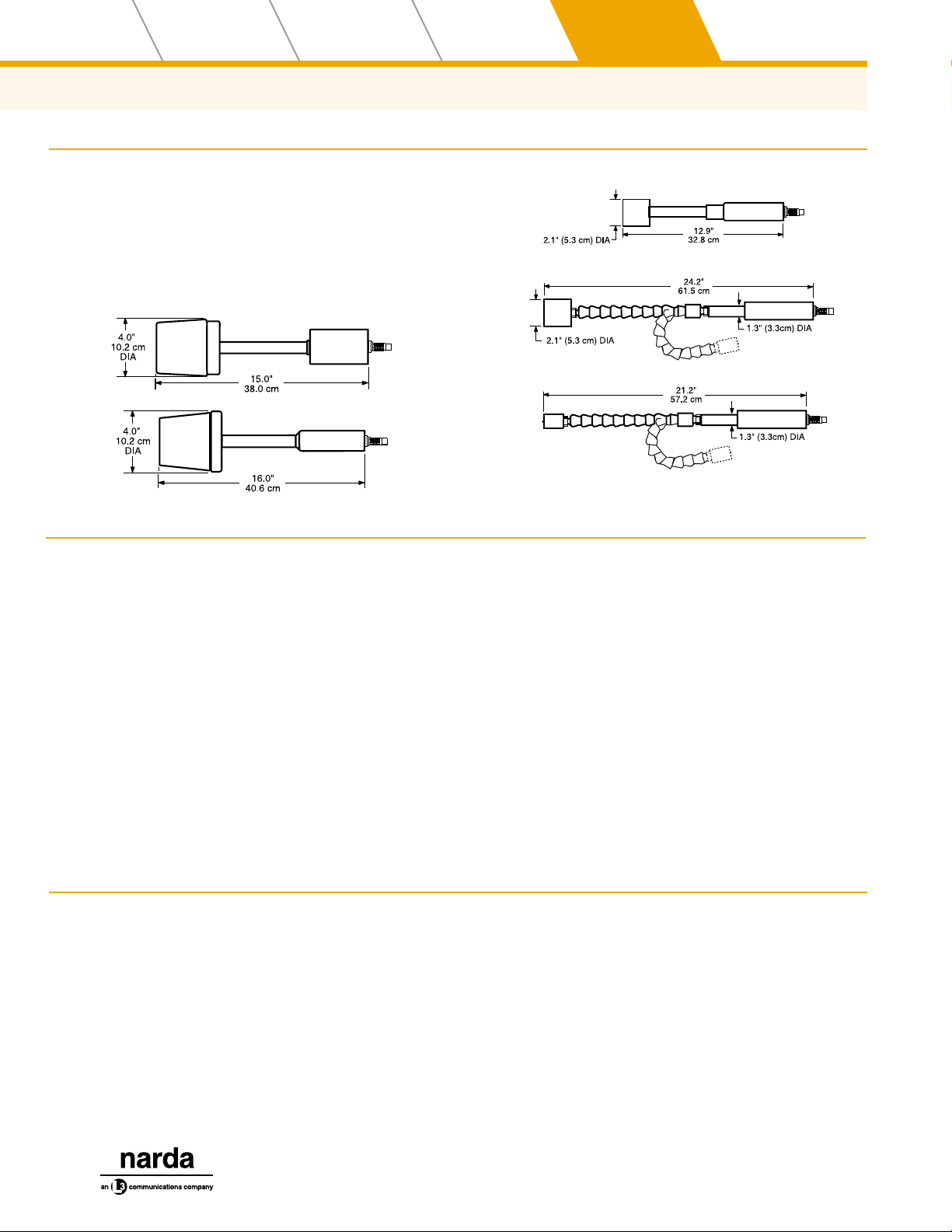
The majority of the 8700D series probes have four inch (10 cm) diameter
heads. The minimum measurement distance for these probes is about 4 in
(10 cm) from the outside surface of the probe. Measurements made at
closer distances can result in inaccurate readings due to capacitive cou
pling. The Models8721D, 8723D, 8725D and 8783D havetwo-inch (5 cm) di
ameter heads that can be used as close as 2 in (5 cm) from the source to the
outside of the probe. These probes are ideal for the measurement of
waveguide leaks. Similarly, the Model 8781D has a one-inch (2.5 cm) di
ameter head with a flexible shaft that isdesigned for locating leaks in densely
packaged microwave systems. The 8783D also has a flexible shaft.
-
-
-
537
Page 2
Wireless
Main
Menu
TOC
Products
Electromechanical
RF Switches
Passive
Components
Active
Components
Electric and Magnetic Field Measurement
ENVIRONMENTAL SPECIFICATIONS
Temperature
Operating -10°C to +55°C
Non-Operating -40°C to +75°C
Humidity 0% to 95%, non-condensing
OUTLINE DRAWINGS
3
4
1
RF Radiation
Safety Products
Power
Meters/Monitors
2
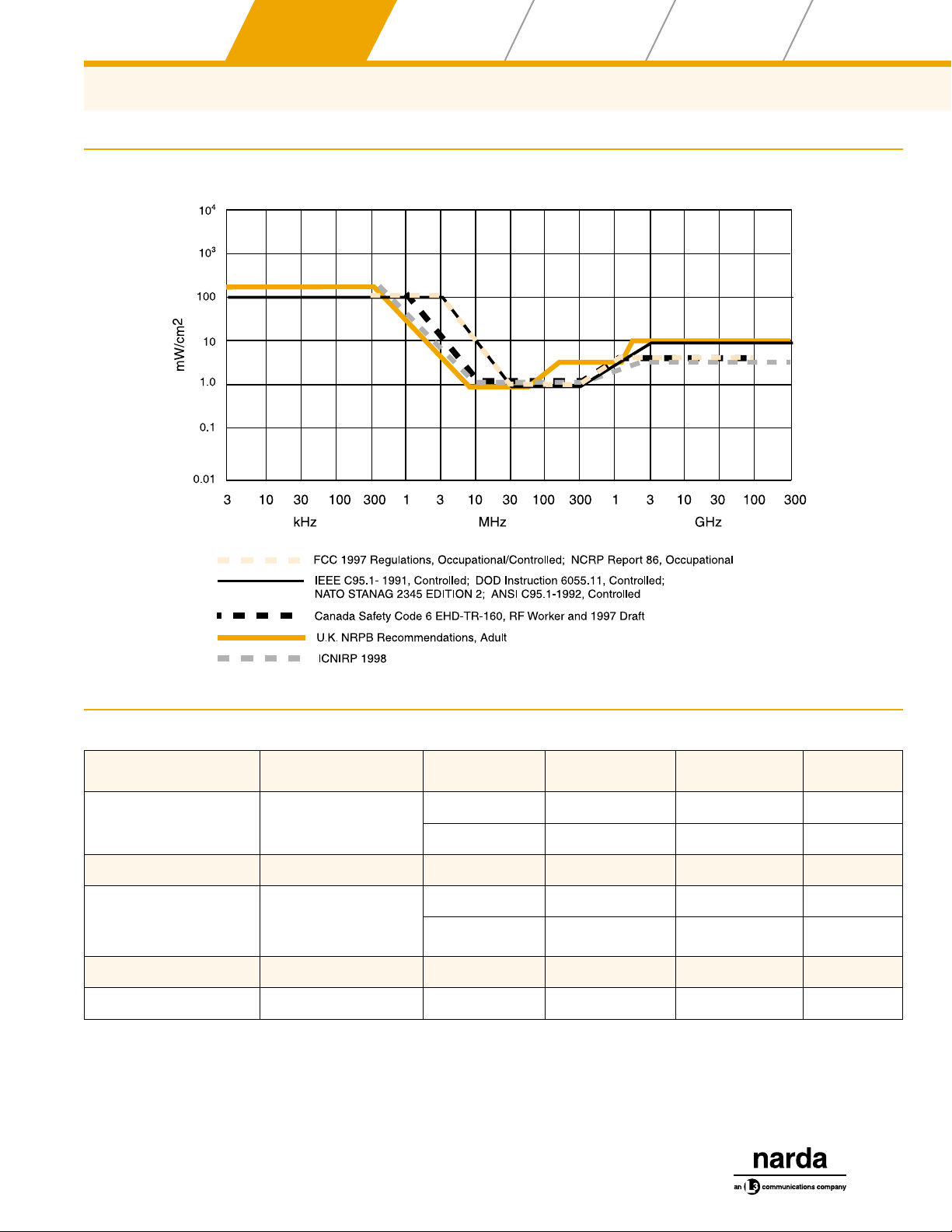
SHAPED FREQUENCY RESPONSE PROBES
The goal in designing and manufacturing a traditional,
“flat” frequency response probe is to make the probe
equally responsive to energy at every frequency within its
rated frequency range. In contrast, Narda’s patented
shaped frequency response probes are designed and
manufactured so that their sensitivity mirrors a particular
standard as closely as possible. For example, many of
the major standards in the world set limits for maximum
exposure at the lowest frequencies to 100 mW/cm
These same standards typically limit exposure in the VHF
region to 1 mW/cm
wave region. A shaped frequency response probe de
signed for such a standard is 100 times more sensitive in
the VHF region than at the lowest frequencies. The result
is that energy from all sources within the probe’s rated fre
quency range are not only summed in terms of RMS
2
and to 5-10 mW/cm2in the micro
2
.
-
-
-
5
power but are also weighted in direct proportion to a particular standard.
The readout on the meter is shown in terms of Percent of
Standard. The full scale of Narda’s shaped probes is typically either 300% or600% of a standard. This permits measurements of exposure environments where the weighted
field strengths range from as high as three to six times the
maximum permissible exposure1 (MPE) level to environ
ments where the levels are less than one percent of the
MPE. For a more complete description of how shaped
probes are used in complex, multi-signal environments,
refer to the application note Measuring RF Levels at
Multi-Signal Sites that begins on page 609.
1
Maximum Persmissible Exposure (MPE) level is only one of several
terms used to designate the limits imposed by various standards.
Other common terms are: Threshold Limit Value (TLV), Permissible
Exposure Level (PEL), action limit, and reference level.
-
SELECTING A SHAPED PROBE
1. Determine the standard that you will be using.
2. Determine which tier of the standard will be
used, i.e., Occupational Environment or
General Population Environment.
3. Determine whether you must measure the
magnetic field as well as the electric field.
4. Select a probe model from the table on the
next page.
538
USA TEL: (1) 631 231-1700 • INT’L TEL: (1) 631 231-1390 • FAX (1) 631 231-1711
E-MAIL: nardaeast@L-3COM.com • www.nardamicrowave.com
Page 3
Power
Main
Menu
TOC
Meters/Monitors
RF Radiation
Safety Products
Active
Components
Passive
Components
Electric and Magnetic Field Measurement
MAJOR INTERNATIONAL STANDARDS AND GUIDANCES
Electromechanical
RF Switches
Wireless
Products
SHAPED PROBE SELECTION GUIDE
STANDARD OR GUIDANCE TIER MODEL
FCC 1997
Japan RCR-38
FCC 1997 General Population B8742D 300 kHz - 3 GHz 600% of Std E
IEEE C95.1-1991
NATO STANAG 2345
ACGIH
Canada Safety Code 6 RF Workers C8722D 300 kHz - 50 GHz 300% of Std E
ICNIRP 1998 Occupational D8722D 300 kHz - 50 GHz 300% of Std E
USA TEL: (1) 631 231-1700 • INT’L TEL: (1) 631 231-1390 • FAX (1) 631 231-1711
E-MAIL: nardaeast@L-3COM.com • www.nardamicrowave.com
Occupational / Controlled
Controlled
Controlled
—
—
A8722D 300 kHz - 50 GHz 300% of Std E
A8742D 300 kHz - 3 GHz 600% of Std E
B8722D 300 kHz - 50 GHz 300% of Std E
A8732D 300 kHz - 200 MHz 300% of Std H
FREQUENCY
RANGE
FULL SCALE
RANGE
FIELD
539
Page 4

Wireless
Main
Menu
TOC
Products
Electromechanical
RF Switches
Passive
Components
Active
Components
Electric and Magnetic Field Measurement
ELECTRIC FIELD PROBES
RF Radiation
Safety Products
Power
Meters/Monitors
MODEL
NO.
a
8782D
8764D 100 kHz to 300 MHz
8760D
8761D
8762D
A8742D
B8742D Shaped
8741D
FREQUENCY
RANGE
3 kHz to 1 MHz
300 kHz to 3.0 GHz
Rated V/m V2/m
0.1mW/cm
200mW/cm
100mW/cm
200mW/cm
0.05mW/cm
100mW/cm
10mW/cm
20mW/cm
100mW/cm2to
200mW/cm
0.6 to 600%
of Standard
50mW/cm
20mW/cm
MEASUREMENT RANGE
2
to
2
2
to
2
2
to
2
2
to
2
2
0.61 to 868
19.4 to 868 376 to 753,000
0.5 to 19.4 0.2 to 377
6.13 to 274 37.6 to 75,300
19.4 to 868 376 to 753,000
——
2
to
2
13 to 274 169 to 75,300 Flat
0.376 to
753,000
2
FREQUENCY
RESPONSE
Flat Active Antenna
Flat
Shaped
A8722D
B8722D
C8722D
300 kHz to 50 GHz
0.3% to 300%
of Standard
— — Shaped
D8722D
8721D
8723D
300 MHz to 50 GHz
8783D
8725D 1 to 40 GHz
e
e
10mW/cm2to
20mW/cm
50mW/cm
100mW/cm
2
2
2
0.5 mW/cm2to
1000mW/cm
6.13 to 274 37.6 to 75,300
13.7 to 614 188 to 376,000
Flat Thermocouple
2
43.4 to 1940
1880 to
3,760,000
Compensated
g
g
Compensated
g
Thermocouple
SENSOR
TYPE
Diode
Diode
and
2
8781D 2 to 18 GHz
a
Model 8782D probe must be used with fiber optic interface Model 8747. Specifications guaranteed for high power range only.
b
Frequency sensitivity can be compensated for by the use of calibration factors marked on the handle of each probe
c
In power (10 log10) units
d
The fields generated to calibrate the probes are accurate within ±0.5 dB
e
This model can be used up to 100 GHz. Refer to the application note on pages 618
f
Isotropic response ±1 dB from 300 kHz to 3 MHz
g
See Shaped Probe Selection Guide on previous page
20mW/cm
20mW/cm
to
2
8.67 to 274
USA TEL: (1) 631 231-1700 • INT’L TEL: (1) 631 231-1390 • FAX (1) 631 231-1711
540
75.3 to 75,300
E-MAIL: nardaeast@L-3COM.com • www.nardamicrowave.com
Page 5

Power
Main
Menu
TOC
Meters/Monitors
RF Radiation
Safety Products
Active
Components
Passive
Components
Electromechanical
RF Switches
Wireless
Products
Electric and Magnetic Field Measurement
FREQUENCY SENSITIVITY
b,c
1dB 0.75dB 1000 1000
±2 dB ±0.75 dB 600 600
±1 dB(3 MHz to 300 MHz)
±2 dB (300 kHz to 3 GHz)
±2 dB from Standard ±0.75 dB
±3.0/-1.5 dB(0.3 MHz to 50 GHz)
±1.5 dB(3 MHz to 50 GHz)
±2 dB from standard ±0.75 dB
ISOTROPIC
RESPONSE
±0.75 dB
±0.75 dB
c
f
CW
OVERLOAD
(mW/cm
2
)
10 10
60 60
600 600
3000%
of Standard
200 15
3000% of
Standard
PEAK
OVERLOAD
(W/cm2)
32 dB above
Standard
32 dB above
Standard
CALIBRATION
FREQUENCIES
d
3, 10, 14, 30,
100, 300, 540,
700, 1000 kHz
0.3, 0.5, 1.0, 3.0, 6.78,
13.56, 27.12, 40.68,
100, 200, 300 MHz
0.3, 0.5, 1.0, 3.0, 6.78
13.56, 27.12, 40.68,
100, 200, 300, 750,
915, 1800, 2450,
2700, 3000 MHz
0.3, 1, 3, 13.56,
27.12, 100, 300,
500, 750, 915,
1800, 2450, 2700,
3000 MHz
0.3, 3, 10, 30,
100, 300, 750
MHz
1, 1.8, 2.45, 4,
8.2, 10, 18, 26.5
40, 45.5 GHz
APPROX
WEIGHT
oz/kg
OUTLINE
DRAWING
25/0.71 1
12/0.34 2
12/0.34 2
12/0.34 2
12/0.34 2
+1.25/-3.0 dB (0.3 GHz to 50 GHz)
±1.25 dB (1 GHz to 50 GHz)
±1.25 dB ±1.0 dB
+1.25/-3.0 dB (2 GHz to 4 GHz)
±1.25 dB (4 GHz to 18 GHz)
±1.0 dB
±1.0 dB
600 200 0.3, 0.75, 1.8, 2.45
4, 5, 6, 7, 8.2,
1500 600 4
9.3, 10, 11, 18,
26.5, 40, 45.5 GHz
10/.028
1.0, 1.8, 2.45, 4, 5,
3000 1000
6, 7, 8.2, 9.3, 10,
10/0.28 3
11, 18, 26.5, 40 GHz
300 60
2, 2.45, 4, 5, 6, 7, 8.2,
9.3, 10, 11, 18 GHz
10/0.28 5
3
USA TEL: (1) 631 231-1700 • INT’L TEL: (1) 631 231-1390 • FAX (1) 631 231-1711
E-MAIL: nardaeast@L-3COM.com • www.nardamicrowave.com
541
Page 6

Wireless
Main
Menu
TOC
Products
Electromechanical
RF Switches
Passive
Components
Active
Components
Electric and Magnetic Field Measurement
MAGNETIC FIELD PROBES
RF Radiation
Safety Products
Power
Meters/Monitors
MODEL
NO.
8752D
8754D
A8732D 300 kHz to 200 MHz
8731D
8733D
a
Frequency sensitivity can be compensated for by the use of the calibration factors marked on the handle of each probe
b
In power (10 log10units)
c
The fields generated to calibrated the probes are accurate within ±0.5dB.
d
See probe selection guide on page 539
FREQUENCY RANGE
300 kHz to 10 MHz
10 MHz to 300 MHz
RATED A/M A2/m
100mW/cm
200mW/cm
1mW/cm
0.3% to 300%
of Standard
10mW/cm
50mW/cm
100mW/cm
2
2 W/cm
20mW/cm
2
2
2
MEASUREMENT RANGE
2
to
2
to
to
2
to
2
2
0.0515 to
2.31
0.163 to
7.29
—— —— Shape 5
0.0163 to
0.729
0.0364 to
1.64
0.00265 to
5.31
0.0275 to
53.1
0.000265 to
0.667
0.00167 to
2.66
8700 SERIES CONNECTOR TYPES
The latest 8700 system equipment uses a new, quick release style 8-pin connector, referred to as “Type L.” Older
models and the 8700 series meters use a 7-pin, screw
type connector, referred to as “Type A.”
Most older style 8700 series probes featured integral cables. The new D series probes require the use of a separate cable. One cable is required for each meter,
regardless of the number of probes. A four foot long
(1.2 m) quick-release cable (Model 8844-04) is supplied
with every hand-held meter. The 8717 series meter
requires the 8743-XX style cable which must be ordered
separately. The 8740 style cables can be used to extend
the length of the 8743 style cables.
Type L Male Cable Connector
Type A Male Cable Connector
SHAPE SENSOR TYPE
FLAT Thermocouple
d
Thermocouple
FLAT Thermocouple
542
USA TEL: (1) 631 231-1700 • INT’L TEL: (1) 631 231-1390 • FAX (1) 631 231-1711
E-MAIL: nardaeast@L-3COM.com • www.nardamicrowave.com
Page 7

Power
Main
Menu
TOC
Meters/Monitors
RF Radiation
Safety Products
Active
Components
Passive
Components
Electromechanical
RF Switches
Wireless
Products
Electric and Magnetic Field Measurement
FREQUENCY
SENSITIVITY
±0.75 dB ±0.5 dB
±1.5 dB from standard ±0.5 dB
±0.5 dB (13 MHz to
200 MHz)
2 dB Max deviation
(10 MHz to 300 MHz)
a,b
ISOTROPIC
RESPONSE
±0.5 dB
CONNECTOR USE
EQUIPMENT MODEL TYPE GENDER
8718B, 8715, 8712 Meters
8717 Series Meters
8700D Series Probes
8747 Fiber Optic Link
c
CW
OVERLOAD
(mW/cm
Standard
2
)
600
6000
900% of
60 20
300 300
PEAK
OVERLOAD
30 dB above
2
(W/cm
600
1000
Standard
)
CALIBRATION
FREQUENCIES
0.3, 0.5, 1, 3,
10 MHz
0.3, 1, 3, 10, 30,
100, 200 MHz
10, 13.56, 27.12,
40.68, 50, 75
100, 150, 200,
250, 300 MHz
c
APPROX
WEIGHT
oz/kg
12/0.34 2
12/0.34 2
12/0.34 2
OUTLINE
DRAWING
PROBE EXTENSION CABLES
L Female
A Female
L Male
L Female
MODEL LENGTH
8740-04 4 ft. (1.2 m) Type A Type A
8740-06 6 ft. (1.8 m.) Type A Type A
8740-12 12 ft. (3.7 m.) Type A Type A
8740-24 24 ft. (7.3 m.) Type A Type A
MALE
CONNECTOR
FEMALE
CONNECTOR
8718, 8716, 8711 Meters
8700 Series Probes (Except D Series)
8745, 8745T, 8746 Fiber Optic Links
A Female
A Male
A Female
USE OF OLDER STYLE PROBES WITH
NEW METERS
A special adaptor cable is required to connect older style
8700 probes with the type A connector and integral cable
to the current hand-held meters that feqture the quick re
lease type L connector. The part number of this 1 ft. (30
cm) type L male to type A female cable is 21787700.
USA TEL: (1) 631 231-1700 • INT’L TEL: (1) 631 231-1390 • FAX (1) 631 231-1711
E-MAIL: nardaeast@L-3COM.com • www.nardamicrowave.com
-
8740-40 40 ft. (12.2 m.) Type A Type A
8743-04 4 ft. (1.2 m.) Type A Type L
8744-04 4 ft. (1.2 m.) Type L Type L
8744-12 12 ft. (3.7 m.) Type L Type L
543
 Loading...