

Page 1
Signal Sources
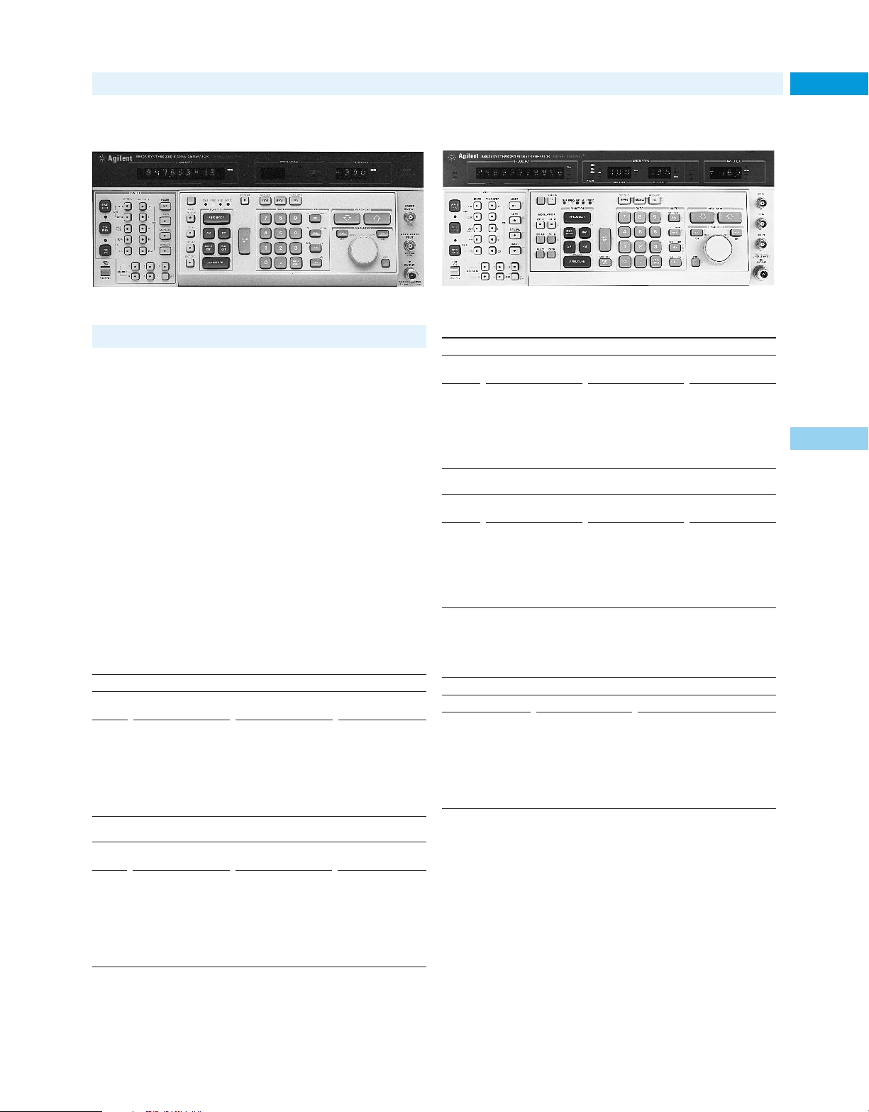
• 10 kHz to 1280 MHz frequency range
• <–147 dBc/Hz SSB phase noise at 10 kHz offset
• 0.1 Hz frequency resolution
• 100 kHz to 2560 MHz frequency range
• AM/FM/M/pulse in one generator
• Internal variable modulation oscillator
8662A 8663A
8662A/8663A Synthesized Signal Generators 1
Residual SSB Phase Noise (dBc/Hz):
Spectral purity is the key contribution of both the Agilent 8662A and
8663A, making them ideal for many radar, satellite communication,
and phase noise measurement applications. Typical absolute phase
noise performance of these generators at a 1 kHz offset is as low as
–135 dBc/Hz, depending on the band of operation.
The frequency range of the 8662A is 10 kHz to 1280 MHz. It
offers versatile AM/FM, using either internal 400 Hz and 1 kHz rates
or externally applied modulating signals which can be either ac- or
dc-coupled. It also has simultaneous modulation capability.
The 8663A and 8662A provide the U.S. Air Force MATE
10 Hz – 108 – 114 – 112 – 119 – 106 – 113
100 Hz – 121 – 126 – 122 – 129 – 118 – 124
1 kHz – 128 – 133 – 131 – 138 – 127 – 134
3 kHz – 128 – 136 – 131 – 139 – 127 – 135
5 kHz – 129 – 138 – 133 – 141 – 129 – 136
10 kHz – 132 – 137 – 142 – 147 – 136 – 142
100 kHz – 132 – 137 – 142 – 147 – 136 – 142
(Modular Automatic Test Equipment) capability, via Option 700.
This option is an external translator that allows the signal generator
to be controlled by the MATE language CIIL (Control Interface
Intermediate Language).
10 Hz – 100 – 107 – 93 – 101 – 88 – 95
8662A Specifications
Frequency
Range: 10 kHz to 1280 MHz (1279.9999998 MHz)
Resolution: 0.1 Hz (0.2 Hz above 640 MHz)
Accuracy and Stability: Same as reference oscillator
Internal Reference Oscillator: 10 MHz quartz oscillator. Aging rate
–10
< 5 x 10
operating environment).
Spectral Purity
Front-Panel Absolute SSB Phase Noise (dBc/Hz):
1 Hz – 68 – 78 – 66 – 76 – 60 – 70
10 Hz – 98 – 108 – 96 – 106 – 90 – 100
100 Hz – 116 – 126 – 115 – 125 – 109 – 119
1 kHz – 126 – 132 – 129 – 135 – 124 – 130
3 kHz – 126 – 135 – 129 – 138 – 124 – 133
5 kHz – 128 – 138 – 131 – 141 – 126 – 136
10 kHz – 132 – 138 – 142 – 148 – 136 – 142
100 kHz – 132 – 139 – 142 – 148 – 136 – 142
/day after 10-day warmup (typically 24 hrs. in normal
Frequency range (MHz)
0.01 to 119.9
Spec Typ Spec Typ Spec Typ
Frequency range (MHz)
320 to 639.9
1
2
120 to 159.9
640 to 1279.9
2
3
160 to 319.9
1280 to 2559.9
2
100 Hz – 112 – 119 – 105 – 112 – 100 – 106
1 kHz – 121 – 128 – 115 – 122 – 109 – 116
3 kHz – 121 – 129 – 115 – 123 – 109 – 117
5 kHz – 123 – 130 – 117 – 124 – 111 – 118
10 kHz – 131 – 136 – 124 – 130 – 118 – 124
100 kHz – 131 – 136 – 124 – 130 – 118 – 124
1
8663A band begins at 0.1 MHz; specifications extend up to and including 119.9999999 MHz.
2
Specifications extend up to and including 0.1 Hz less than the starting frequency of the
next band.
3
Specifications extend up to and including 1279.9999998 MHz.
4
This band available on 8663A only; specifications extend up to and including
2559.9999996 MHz.
Option 003 Specified SSB Phase Noise for Rear-Panel 640 MHz Output:
1 Hz – 54 –64
10 Hz – 84 –94
100 Hz – 104 –114
1 kHz – 121 –126
3 kHz – 121 –127
5 kHz – 129 –138
10 kHz – 145 –149
100 kHz – 157 – 159
SSB Broadband Noise Floor in 1 Hz BW at 3 MHz Offset From Carrier:
<–146 dBc for fc between 120 and 640 MHz at output levels
4
above +10 dBm.
Spec Typ Spec Typ Spec Typ
1 Hz – 54 – 64 – 48 – 58 – 42 – 52
10 Hz – 84 – 94 – 78 – 88 – 72 – 82
100 Hz – 103 – 114 – 97 – 108 – 92 – 102
1 kHz – 118 – 125 – 112 – 119 – 106 – 113
3 kHz – 118 – 127 – 112 – 121 – 106 – 115
5 kHz – 120 – 130 – 114 – 124 – 108 – 118
10 kHz – 131 – 136 – 124 – 130 – 118 – 124
100 kHz – 131 – 136 – 124 – 130 – 118 – 124
High-Performance RF Signal Generators (cont.)
Frequency range (MHz)
0.01 to 119.9
Spec Typ Spec Typ Spec Typ
Frequency range (MHz)
320 to 639.9
Spec Typ Spec Typ Spec Typ
1
2
120 to 159.9
640 to 1279.9
2
Spec Typ
160 to 319.9
3
1.28 to 2559.9
2
4
211
8662A
8663A
5
Internet URL www.agilent.com/find/tmc Product & Order Info See page 604
Page 2

Signal Sources
8662A
8663A
212
High-Performance RF Signal Generators (cont.)
Spurious Signals:
Frequency Range (MHz)
0.01 to 120 to 160 to 320 to 640 to
120 160 320 640 1280
Spurious non-harmonically –90 –100 –96 –90 –84
1, 2
related
Sub-harmonically related
1 , 3f ,
etc.
(
2 2
Power-line (60 Hz) related
or microphonically –90 –85 –80 –75 –70
generated (within 300 Hz)4dBc dBc dBc dBc dBc
Harmonics < –30 dBc
)
Output
Level Range: +13 to –139.9 dBm (1V to 0.023 µV
Resolution: 0.1 dB
Absolute Level Accuracy: (+15˚ to +45˚ C): ±1 dB between +13 and
–120 dBm; ± 3 dB between –120 and –130 dBm
SWR: Typically from 1.5 to 1.8, depending on output level and frequency
Reverse Power Protection: Typically up to 30 W or ± 8 Vdc
Amplitude Modulation
5
Depth: 0 to 95% at output levels of +8 dBm and below (+10 dBm in uncor-
rected mode). AM available above these output levels but not specified.
Resolution: 1%, 10 to 95% AM; 0.1%, 0 to 9.9% AM
Incidental PM: (at 30% AM): 0.15 to 640 MHz, < 0.12 radian peak;
640 to 1280 MHz, < 0.09 radian peak
Incidental FM: (at 30% AM): 0.15 to 640 MHz, < 0.12 x f
640 to 1280 MHz, < 0.09 x f
Indicated Accuracy: ± 5% of reading ± 1% AM. Applies for rates given
in table below, internal or external mode, for depths ≤90%.
Rates and Distortion with Internal or External Modulating Signal:
AM Distortion
Frequency 0 to 30% 30 to 70% 70 to 90%
Range AM Rate AM AM AM
0.15 to 1 MHz dc to 1.5 kHz 2% 4% 5.75%
1 to 10 MHz dc to 5 kHz 2% 4% 5.75%
10 to 1280 MHz dc to 10 kHz 2% 4% 5.75%
Frequency Modulation
FM Rates: (1 dB bandwidth): External ac, 20 Hz to 100 kHz;
external dc, dc to 100 kHz
FM Deviation: 25 to 200 kHz, depending on carrier frequency
Indicated FM Accuracy: ± 8% of reading plus 10 Hz (50 Hz to 20 kHz)
FM Resolution: 100 Hz for deviations < 10 kHz, 1 kHz for deviations
≥ 10 kHz
Incidental AM: (AM sidebands at 1 kHz rate and 20 kHz deviation):
< –72 dBc, f
c
< 640 MHz; < –65 dBc, fc≥ 640 MHz
FM Distortion: < 1.7% for rates < 20 kHz, < 1% for rates < 1 kHz
Center Frequency Accuracy and Long-Term Stability in AC Mode:
Same as CW mode
Supplemental Characteristic
Frequency-Switching Speed:5From 420 µs to 12.5 ms, depending on the
programming mode
dBc dBc dBc dBc dBc
none none none none dBc
rms
into 50 Ω)
mod
mod
8663A Specifications
The 8663A signal generator is related to the 8662A in both concept and
structure. Like the 8662A, the 8663A is an extremely low phase noise signal source, incorporating signal generator modulation capabilities and
output characteristics. The 8663A also offers increased frequency range
to 2560 MHz, increased output level to +16 dBm, and the addition of phase
and pulse modulation while maintaining high spectral purity. The result is
–75
proven circuitry of the 8662A. Thus, the 8662A and 8663A share many of
a highly flexible and powerful signal generator that uses and extends the
3
the same specifications.
Frequency
Range: 100 kHz to 2560 MHz (2559.9999996 MHz)
Resolution: 0.1 Hz (f
0.2 Hz (640 MHz to 1280 MHz);
0.4 Hz (f
Accuracy, Stability, and Internal Reference Oscillator:Identical to 8662A
c
c
≥1280 MHz)
<640 MHz);
Spectral Purity
(See 8662A specifications)
Spurious Signals: Identical to 8662A, except that for f
1280 and 2560 MHz the spurious non-harmonics are –78 dBc; the subharmonically related (f/2, 3f/2, etc.) between 640 and 1280 MHz are
–70 dBc and between 1280 and 2560 MHz are –40 dBc; and the powerline (60 Hz) or microphonically generated spurious are –65 dBc.
Harmonics: <–30 dBc, ≤+ 13 dBm output; <–25 dBc, + 13 dBm to
+ 16 dBm output, f
c
<1280 MHz; <–25 dBc, fc≥1280 MHz
c
between
Output
;
Level Range: + 16 dBm to –129.9 dBm
Resolution: 0.1 dB
Absolute Level Accuracy: (+ 15˚ C to + 45˚ C): ± 1 dB, + 16 dBm to
–119.9 dBm; ± 3 dB, –120 dBm and below
SWR: <1.5
Amplitude Modulation
Depth: 0 to 95% at levels of + 10 dBm and below
Resolution: 0.1%
Incidental FM: (at 30% AM): Identical to 8662A except: <0.3 x f
c
1280 ≤f
<2560 MHz
mod
for
Indicated Accuracy: ± 6% of reading ± 1% AM (400 Hz and 1 kHz, depth 90%)
AM Bandwidth: (1dB): dc to >1.5 kHz, 0.15 MHz ≤f
dc to >5 kHz, 1 MHz ≤ f
c
≤10 MHz; dc to >10 kHz, fc>10 MHz:
c
<1 MHz;
external dc coupling. External ac coupling or internal;
low-frequency coupling is 20 Hz.
Distortion: (400 Hz and 1 kHz): < 2% (0 to 30% AM); < 3% (30 to 70% AM);
< 4% (70 to 90% AM)
Frequency Modulation
FM Rates: (1 dB bandwidth): External ac, 20 Hz to 100 kHz, external dc,
dc to 100 kHz
Maximum Allowable Peak Deviation: Identical to 8662A for f
100 kHz and 1280 MHz. Up to 400 kHz for f
c
between 1280 and 2560 MHz.
Indicated FM Accuracy: (50 Hz to 20 kHz): ± 7% of setting +10 Hz
FM Resolution: 100 Hz to 1 kHz, depending on f
c
and deviation setting
Incidental AM: (AM sidebands at 1 kHz rate and 20 kHz deviation):
c
<–72 dBc (10 ≤ f
< 2560 MHz)
FM Distortion: <1% (400 Hz and 1 kHz rates); <1.7% (rates less than 20 kHz)
1
In the remote mode it is possible to have microprocessor clock-related spurious signals
spaced 3 MHz apart at an absolute level of typically less than –145 dBm.
2
Spurious signals can be up to 3 dB higher in the dc FM mode.
3
f/2 spurs not specified for carrier frequencies above 850 MHz.
4
At a 50 Hz line frequency, power-line or microphonically-related spurious signals
may be up to 3 dB higher and appear at offsets as high as 1 kHz from the carrier.
5
Due to automatic leveling loop bandwidth changes, brief (30 ms) level inaccuracies
may occur when switching through 150 kHz and 1 MHz RF output frequencies.
c
between
Page 3

Signal Sources
Phase Modulation (Option 002)
Maximum Peak Phase Deviation: From ± 25˚ for fcbetween
120 and 160 MHz to ± 400˚ for f
Maximum Rate: From 10 kHz for f
10 MHz for f
c
between 640 and 2560 MHz
Phase Deviation Resolution: 1˚ (0.1 ≤ f
2˚ (640 ≤ f
c
<1280 MHz); 4˚ (1280 ≤ fc<2560 MHz)
Phase Modulation Distortion: 10% at maximum rate
c
between 1280 and 2560 MHz
c
between 0.15 and 10 MHz to
c
<640 MHz);
Biphase Modulation (BPSK)
Biphase modulation is available on the standard 8663A for fcless than 640
MHz and available for all f
Deviation: ± 90˚
Carrier Null when Modulated with 1 MHz, 50% Duty Cycle
Square Wave: >25 dBc
Modulation Input Required: TTL positive true. The internal modulation
oscillator can be used for 50% duty-cycle modulation. External input is
on rear panel.
Pulse Modulation
Pulse On/Off Ratio: >80 dB (50 to 2560 MHz)
Pulse Rise/Fall Time: <250 ns (50 to 120 MHz); < 800 ns (120 to 640 MHz);
<100 ns (f
Pulse Repetition Frequency (50% duty cycle):
Internal Modulation Oscillator
c
≥ 640 MHz)
Internal: 10 Hz to 99.9 kHz
External: 10 Hz to 2 MHz, 50 MHz < f
10 Hz to 5 MHz, f
Rates: 10 Hz to 99.9 kHz
Frequency Resolution: 3 digits
Frequency Accuracy: Same as reference oscillator
Output Level (available on rear panel): 1 V peak into 600 Ω
Output Impedance: 600 Ω
Flatness (referenced to 1 kHz): < ± 1%
Distortion: < 1%
c
with Option 002.
1
c
>640 MHz
c
<640 MHz;
Other 8662A and 8663A Information
Remote Programming: The GPIB interface is standard on the 8662A and
8663A signal generators. All functions controlled from the front panel,
with the exception of the line switch, are programmable with the same
accuracy and resolution as in manual mode.
Operating Temperature Range: 0˚ C to + 55˚ C
Leakage: Meets radiated and conducted limits of MIL-STD-461A
methods RE02 and CE03 as well as BVDE 0871
Power Requirements: 115 (90 to 126) V or 230 (198 to 252) V;
48 to 66 Hz; 450 VA max
Size:
8662A: 178 mm H x 425 mm W x 572 mm D (7 in x 16.75 in x 22.5 in)
8663A: 178 mm H x 425 mm W x 642 mm D (7 in x 16.75 in x 25.3 in)
Note: depth includes front panel depth of 45 mm (1.75 in).
Weight: 8662A: net, 30 kg (65.5 lb); shipping, 36 kg (80 lb)
8663A: net, 33.8 (74 lb); shipping, 40 kg (88 lb)
Key Literature
Synthesized Signal Generator 10 kHz to 1280 MHz
Technical Data, p/n 5953-8402
Synthesized Signal Generator 100 kHz to 2.56 GHz
Technical Data, p/n 5953-8376
High-Performance RF Signal Generators (cont.)
11721A
8663A 2560 MHz Signal Generator
2
Opt 001 RF Connectors on Rear Panel Only
Opt 002 Wideband Linear Phase Modulation
Opt 003 Specified SSB Phase Noise for 640 MHz Output
Opt 907 Front Handle Kit (5061-9690) 4
Opt 908 Rack Flange Kit (5061-9678) 4
Opt 909 Rack Flange Kit w/Front Handles (5061-9684) 4
Opt 910 Additional Operation and Calibration Manual 4
(08663-90069) and Service Manuals (08663-90071)
Opt 915 Add Service Manual (08663-90071) 4
Opt W30 Extended Repair Service (see page 70)
Opt W32 Calibration Service (see page 70)
11714A Service Support Kit (required for servicing
8662A/8663A)
1
Pulse modulation is available for fc< 50 MHz but is unspecified.
2
GPIB cables not supplied. For description and price, see page 568.
4 Indicates QuickShip availability.
11721A Frequency Doubler
The 11721A doubler is an ideal accessory for extending the usable
frequency range of signal generators, frequency synthesizers, or
other signal sources. Operating on input frequencies of 50 MHz to
1300 MHz, it provides a doubled output in the range of 100 MHz to
2600 MHz. The 11721A will work well with any RF source with an
output in the range of 50 to 1300 MHz.
The 50 Ω passive circuit of the 11721A offers low conversion
loss, low spurious, and excellent flatness over its entire frequency
range when operated above +10 dBm.
11721A Specifications
Input Frequency Range: 50 to 1300 MHz
Output Frequency Range: 100 to 2600 MHz
Conversion Loss (+13 dBm input, 50 to 1280 MHz): < 15 dB
Spurious Referenced to Desired Output Frequency f:
(+ 13 dBm input with harmonics <–50 dBc, 50 to 1280 MHz):
f/2, –15 dB; 3f/2, –15 dB
Input SWR: 1.5 typical
Input/Output Impedance: 50 Ωnominal
Operating Temperature Range: 0˚ to 50˚ C
Connectors: Input, type-N male; output, type-N female
Size: 20.5 mm H x 30 mm W x 161 mm D (.19 in x 1.19 in x 6.38 in)
Weight: Net, .02 kg (0.5 lb); shipping, 0.4 kg (1 lb)
Ordering Information
11721A Frequency Doubler
Opt W30 Extended Repair Service (see page 567)
213
8662A
8663A
11721A
5
Ordering Information
8662A 1280 MHz Signal Generator
Opt 001 RF Connectors on Rear Panel Only
Opt 003 Specified SSB Phase Noise for 640 MHz Output
Opt 907 Front Handle Kit (5062-3990) 4
Opt 908 Rack Flange Kit (5062-3978) 4
Opt 909 Rack Flange Kit w/Front Handles(5062-3984) 4
Opt 910 Two Sets of Operating and Service Manuals 4
(08662-90069)
Opt W30 Extended Repair Service (see page 70)
Opt W32 Calibration Service (see page 70
Internet URL www.agilent.com/find/tmc Product & Order Info See page 604
2
 Loading...