

Page 1

value of the capacitor as frequency changes from
50 KHz to 400 MHz.
A tuned voltmeter such as an EMI meter is
recommended as the detector for further
isolation of unwanted frequencies, such as
harmonics of the signal generator. If the generator waveform is “clean.”An untuned meter can be
used if it is terminated in 50 ohms and preserves
a 50 ohm coaxial circuit throughout the
frequency range.
The reactance of the built-in series capacitor from
the generator to the power line terminal presents
very little loss at 50 KHz.At 400 Hz its reactance is
about 362 ohms.Therefore, it represents a path by
which 400 Hz power voltages can be fed back to
damage the output circuit of the signal generator.
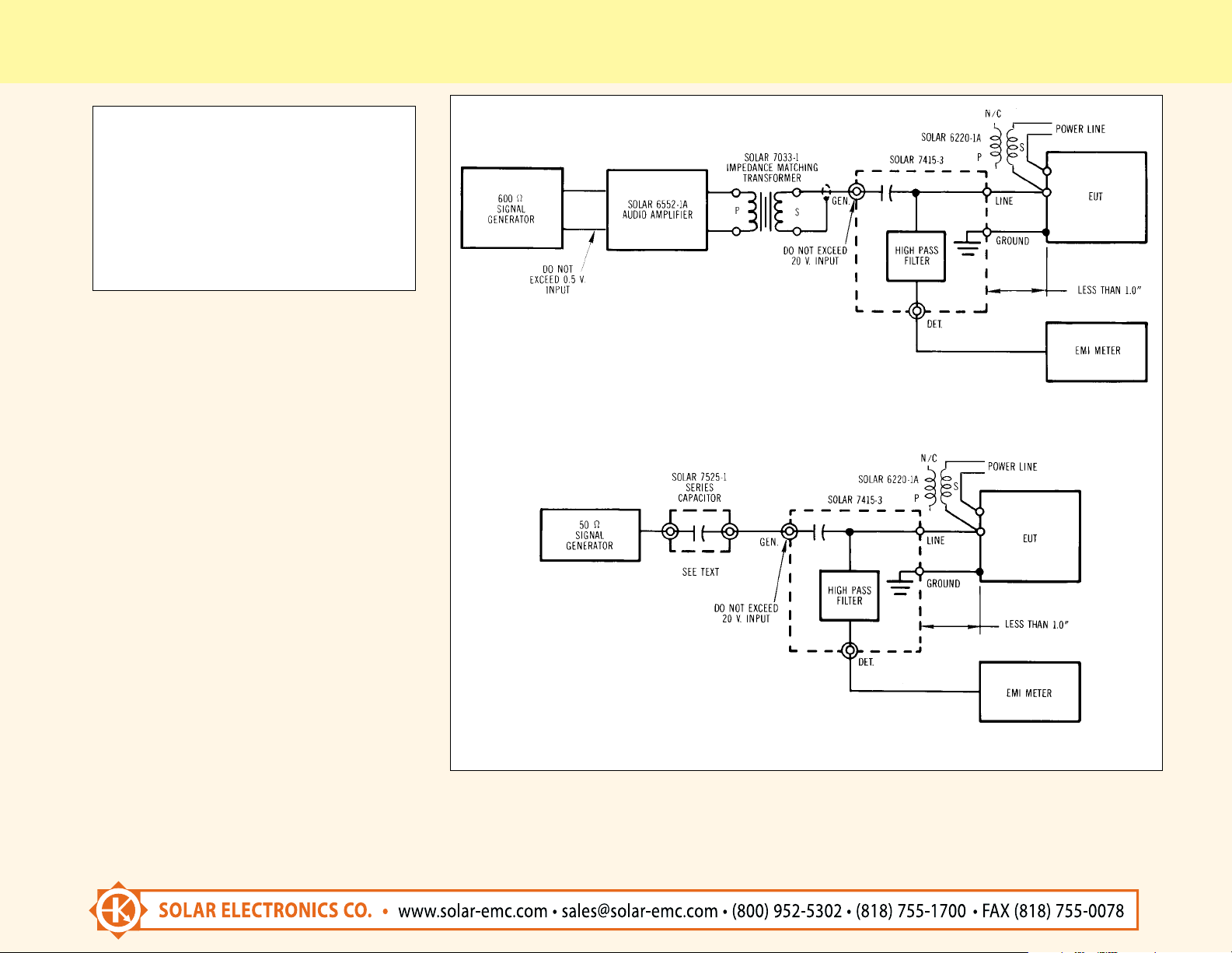
To avoid this,one suggestion is to use an isolating
transformer at the output of a low impedance
signal source. Figure 1 shows the use of the
Model 6552-1A Audio Amplifier and the Typ e
7033-1 Impedance Matching Transformer. This
arrangement can be used for injection levels
up to 20 volts r.m.s. from 50 KHz to 500 KHz with
satisfactory results.
At frequencies above 500 KHz, we recommend
that a 50 ohm signal generator be used as indicated in Figure 2 except that a small capacitor
must be connected in series between the
generator and the Type 7415-3 R.F. Coupler.
Solar Type 7525-1 is 0.1 microfarad, fitted
with BNC connectors.
The reactance of this series capacitor reduces the
power frequency voltage to a safe limit so that
the output circuit of the generator will not be
damaged. At 500 KHz, the r.f. signal is not greatly
attenuated.
At frequencies above 20 or 30 MHz, the connections from the banana jacks to the test sample will
create discontinuities that cannot be removed
from the setup. It is recommended that the wires
from the banana jacks be less than one inch long
to minimize VSWR anomalies.
DIMENSIONS
2.0" (51 mm) X 2.5" (63.5 mm) plus mounting
flanges x 1.25" (31.25 mm) high.
Application Information
TYPE 7415-3 R.F. COUPLER AND HIGH PASS FILTER
There are those who disagree with the r.f.
conducted susceptibility test setup of Method
CS02 of MIL-STD-462. Homemade rigs have
sprouted to comply with the coupling capacitor
requirement, each with it own disadvantage.
Our little Type 7415-3 R.F.Coupler is the answer.
A neat little box with BNC connectors and a pair
of binding posts, it is rated at 270 V.A.C.at the LINE
terminals and 20 volts PMS into the GEN port.
Looks good and does a fine job.
The test setup diagram of the specification will
result in power frequency voltages at the
voltmeter terminals. If an untuned voltmeter is
used, it is difficult to measure a one volt r.f. signal
in the presence of the a.c. line voltage. It is not
practical to use an EMI meter for this, unless the
Type 7415-3 is placed in series with it. Otherwise,
the power frequency voltage can damage the
input circuit of the EMI meter.
The Type 7415-3 contains a high pass filter in
series with the detector circuit to eliminate power
frequency voltages and allow r.f. signals from
50 KHz to 400 MHz to pass to the EMI meter as
required. The high pass filter consists of three
stages of an R-C network using series capacitors
and shunt resistors. Using resistors instead
of inductors enables the unit to cover a wide
frequency range, with a 40 dB insertion loss in
the pass band.This makes it necessary to multiply
the detected voltage by a factor of 100 for the
measurement of the injected voltage.
The series capacitor in the Type 7415-3 consists
of several styles of capacitors in parallel. Mica,
ceramic and wrapped capacitors exhibit different
characteristics versus frequency and the
combination eliminates the need to change the
TYPE 9132-1 R.F. COUPLER AND HIGH
PASS FILTER
This unit is a high voltage version of the Typ e
7415-3.It is electrically similar, but in a larger
case and with a rating of 500 VAC at the LINE
terminals and 20 volts rms into the GEN. Port.
Dimensions: 2.88" (73 mm) x 3.06" (78 mm) plus
mounting flanges x 2.0" (51 mm) high.
TYPE 9407-1 A THREE PHASE R.F. COUPLING
NETWORK
MIL-STD-462 notice 5, method CS02 requires
simultaneous coupling of the r.f. susceptibility
69
Page 2
TYPE 7415-3 R.F. COUPLER AND HIGH PASS FILTER (continued)
it is deemed to have passed the test.
Even though the signal input port of
the Type 7415-3 is rated at 20 volts, it is not
recommended that the power of the signal
source be increased beyond one watt in an
effort to reach a one volt injection level.
OR 9132-1
OR 9132-1
FIG. 1 TEST SETUP FOR FREQQUENCIES FROM 50 KHz - 500 KHz
FIG. 2 TEST SETUP FOR FREQQUENCIES FROM 500 KHz - 400 MHz
Test Method CS02 requires injection of the signal
from a 50 ohm generator capable of seven volts
output. This is equivalent to a one watt source.
There are two conditions which could inhibit
the injection of one volt r.f. into the Equipment
Under Test:
1) If the r.f. impedance looking into the power
terminals of the Equipment Under Test is
considerably lower than 50 ohms at the
injection frequency, the injected signal will
be shunted and it may not be possible to
achieve the required injection voltage with a
one watt source.
2) If the connections to the power source are
heavily by-passed as in the case of screen
room testing, this will also shunt the injection
voltage so that the required level cannot be
reached. This can be prevented by inserting
an inductor in the power line as
indicated in Figure 1 and Figure 2.
The secondary of the Solar Type 6220-1A
Transformer can be used as this inductor.
Therefore, the test setup must be
carefully monitored to keep the signal source
from exceeding the required seven volts. If the
Equipment Under Test does not malfunction
with a seven volt signal from a 50 ohm source,
signal into all three wires of a three phase
power system. The Type 9407-1 network
provides this capability in a neat little box.
The unit includes a high pass filter for the
elimination of power frequency voltages.
Rating of 270 VAC at the LINE terminals and 20
volts rms into the GEN. Port.
Dimensions: 2.88" (73 mm) x 3.06" (78 mm) plus
mounting flanges x 2.0" (51 mm) high.
70
 Loading...