

Page 1
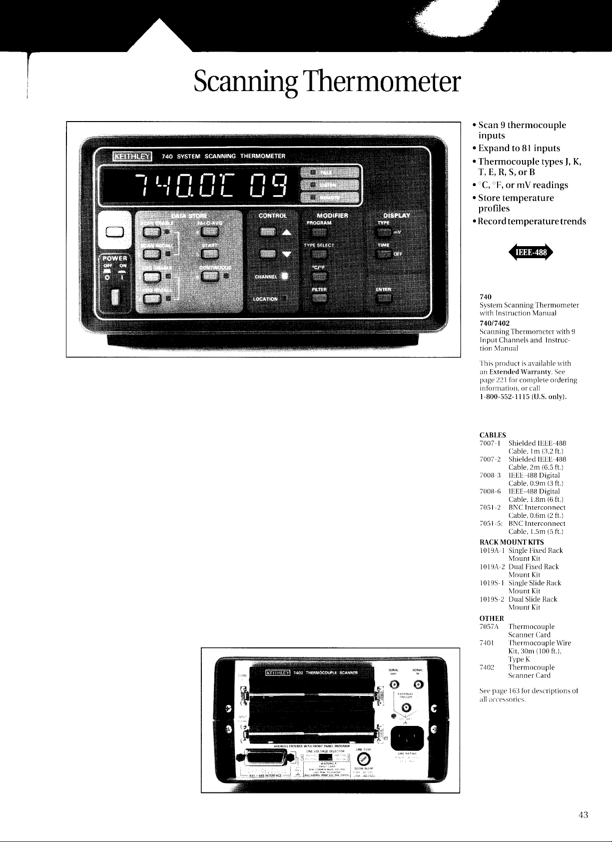
The Model 740 Programmable Thermometer
has a built-in reference junction and will
linearize any of 7 different thermocouple types.
The Model 740/7402 combination includes
nine channels of thermocouple input. An
I
EEE-488 interface port is included for easy
system integration or connection to an IEEE488 printer for data logging.
Input Expansion
The Model 740/7402 can be expanded up to 81
i
nputs by selecting a Model 705 or 706 Scanner
and configuring these with additional 7402 or
7057A thermocouple scanner cards, each xvith
9 inputs. The control for these expansion units
i
s through a serial loop connected by standard
coaxial cable, thereby allowing expansion
without using additional IEEE-488 addresses.
Input Programming
Each input can be selected for any of J, K, T, E,
R, S, or B type thermocouples, or for voltage
readback up to 100mV with 1 uV sensitivity.
Any input can also be turned off, allowing the
i
nstrument to skip that channel in the scan
sequences. Open thermocouple conditions are
detected and displayed.
Monitor Temperature
Trends
A single input can be read at
programmable intervals to
monitor temperature trends.
Rates up to 20 readings/second
are available for determining
rapid temperature variations,
and the data can be stored in
t
he internal
also be transferred to a computer file over the built-in
lEEE-488
memory. Data can
bus.
Locate hot spots and examine time-dependent
thermal characteristics. Scan intervals are
programmable, and the maximum rate of 20
readings/second assures a minimum of time
skew between input samples for monitoring
temperature changes.
A SMART PRINT feature can locate the address
and send data to any IEEE-488 printer for data
l
ogging of results in a bench configuration.
Non-Volatile Memory
An internal memory stores up to 100 readings.
Data can be recalled from the front panel or
transferred in a block transfer to a controller.
The Model 740 will also give HI,
AVERAGE of the data memorv.
Simple, Reliable Calibration
Calibration of the Model 740 is easy-there are
no mechanical adjustments. Simply present
the calibration voltages to the input and tell
the instrument to calibrate. Constants are
stored in non-volatile
i
nstrument's accuracy.
memory, to maintain the
LO, and
Page 2
 Loading...