

Page 1
ment of the scope, it is ready for viewing the
spike.When the READY lamp indicates the storage
circuit has been charged to the selected peak
voltage, the pushbutton is depressed which
triggers the sync circuit of the oscilloscope.
All connections to the Model 7399-2 are isolated
from the chassis.The chassis is grounded through
the third wire in the power cord in accordance
with safety regulations.
The Model 7399-2 is provided with two plug-in
assemblies which enable it to be configured for
series or parallel injection as described in the
appendices of MIL-STD-1399:
1) Using the P/N 739945 Plug-in Unit, the
equipment is ready for series injection as
described in Appendix B of the MIL spec.
In this mode, the operation of the Model
7399-2 is identical to Model 7399-1.When
using the P/N 739945 Plug-in Unit, heavy
duty output jacks provide connections in
series with loads up to 100 amperes r.m.s.
The mating plugs are well insulated and
will handle power line voltages in excess of
500 volts, r.m.s.
2) Using the P/N 739950 Plug-in Unit,
the equipment can be used for parallel
injection of the spike on single or three
phase power circuits as described in
proposed Appendices A, C, and D of the
MIL spec. This method requires the use of
external components determined by the
characteristics of the item being tested.
MODEL 7399-2 SPIKE GENERATOR
2500 VOLTS
for conducted transient susceptibility testing
APPLICATION
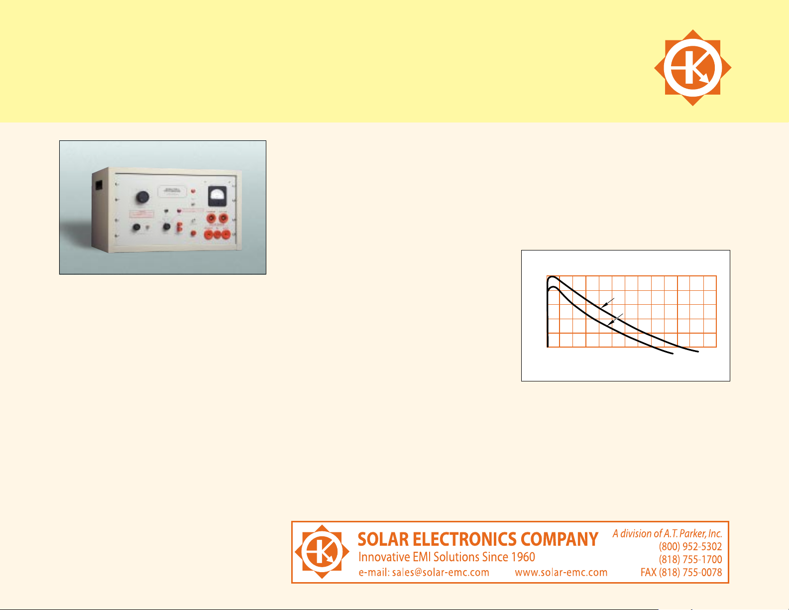
The Model 7399-2 Spike Generator is a “Big Bang”
unit capable of providing high energy spikes
with amplitudes adjustable up to 2500 volts,
peak, into low impedance loads, as required
by paragraph 4.8.5.4 of MIL-E-16400G and
described in MIL-STD-1399 Appendices A, B, C,
and D.The shape of the spike approximates Figure
1 of MIL-STD-1399, Section 103, as shown.
DESCRIPTION
Modes of operation:
Repetitive spikes up to 2500 volts peak at two
pulses per minute.
Single non-synchronous spike actuated by a
pushbutton on the panel.
Sync functions provide for placing the spike on
the power frequency waveform of 50,60 or 400
Hz power lines.The spike can be moved to any
point o the sine wave from 0 to 360.
A SYNC TEST function is provided for adjusting
the trigger circuit of the associated oscilloscope
for response to a single pulse. After this adjust-
21
KV
2.5
2.0
1.5
1.0
0.5
0
0
20 40 60
OPEN CIRCUIT
0.5 OHM LOAD
MICROSECONDS
80
100 120
Page 2
MODEL 7399-2 SPIKE GENERATOR
USEFUL ACCESSORIES (Not Included)
Type 6220-1A Transformer. Can be used as a
high current series inductor.
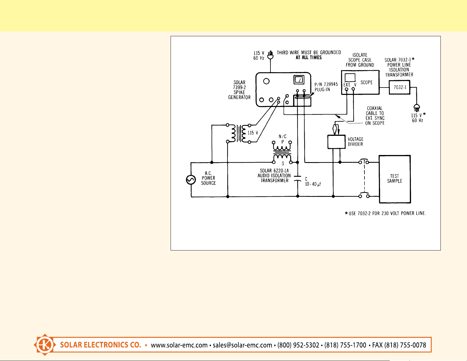
Type 7032-1 Isolation Transformer. For remov-
ing power ground from the case of the scope (see
diagram above).
TEST CIRCUIT FOR APPLICATION OF LINE-TO-LINE HIGH VOLTAGE SPIKES TO NAVY EQUIPMENT
SUPPLIED BY SINGLE PHASE A.C. POWER. REF.: MIL-STD-1300, APPENDIX B.
SPECIFICATIONS
NO LOAD 0.5 OHM LOAD
Peak Amplitude: 100-2500 V 100-2000 V
Rise Time: ≈1 S ≈2 S
Duration to
50% of Peak: ≈50 S ≈31 S
Duration to
Zero Crossover: ≈100 S ≈77 S
Repetition Rate: 2 pulses per minute.
Phase Adjustment: Spike position adjustable
from 0 to 360 on 50, 60 or 400 Hz sine wave.
Internal Impedance: Less than 0.1 ohm.
Peak Output Power: 8 Megawatts into 0.5 ohm
load.
Power Current in Series Injection Mode:
Handles up to 100 amperes of current at power
frequencies.
Power Requirements: 115 volts 60 Hz, 2.0
amperes (230 volts 50 Hz, 1.0 ampere available).
Size: 21.06" wide, 12.56" high,15.50" deep
(53.5 cm x 31.9 cm x 39.4 cm).
Weight: 70 pounds plus 5 pounds for accessories.
Total Shipping Weight: 75 pounds.
* Spike duration can be changed from ≈20 S to
≈100 S using internal jumpers.
ACCESSORIES (Supplied)
P/N 739945 Plug-in Unit for series injection of
spike into power lines.
P/N 739950 Plug-in Unit for parallel injection
(using external components).
Mating connectors: Two 100 ampere styles, for
power connections; two 50 ampere styles, for
external resistor.
22
 Loading...