

Page 1
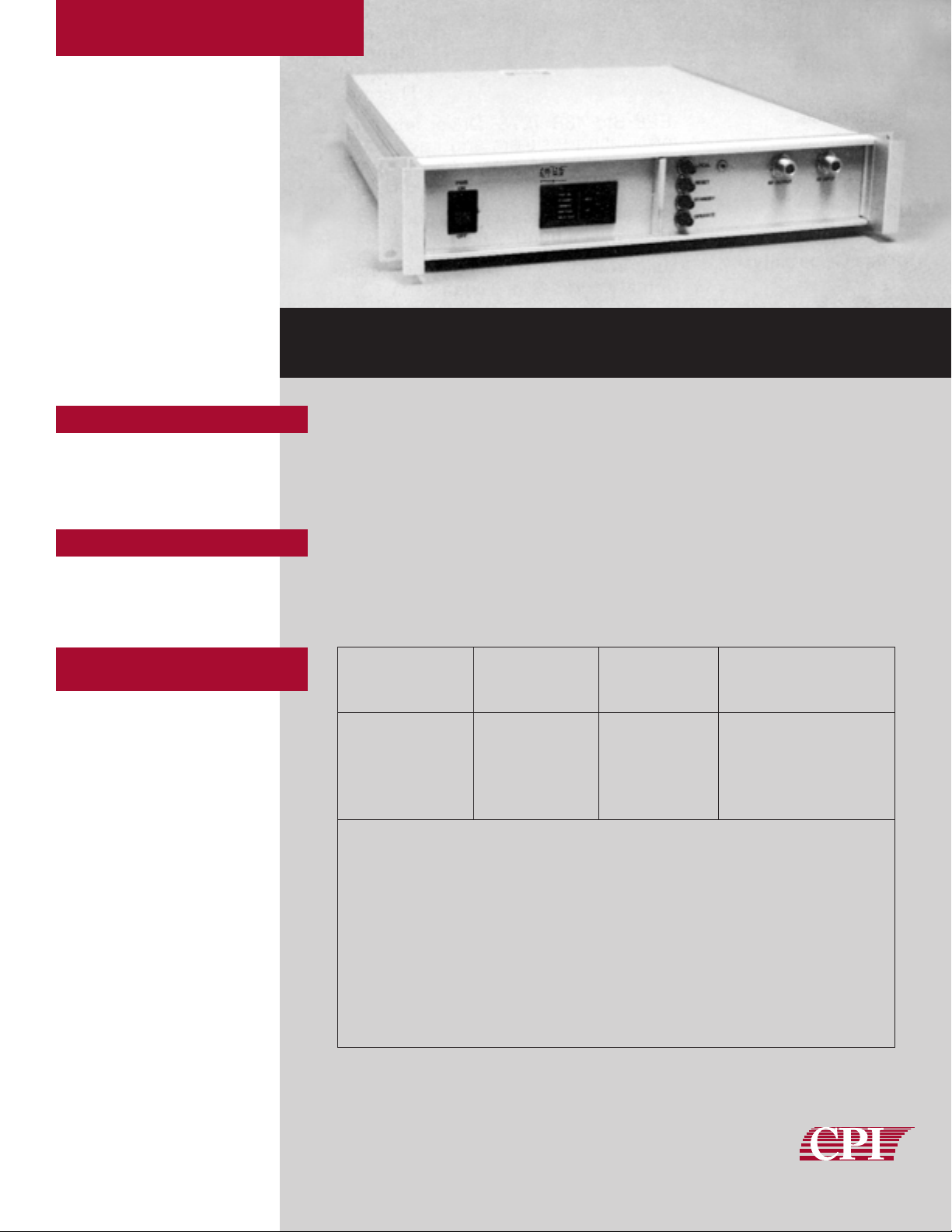
6900K6 Series
• IEEE-488
• CIIL /MATE Compatible
• Talker and Listener
• Interface Built-In
The 6900K6 Series are GPIB controllable versions of the popular CPI 6900K4 series
low power commercial TWT amplifiers.
CPI 6900K6 series TWT amplifiers are manufactured with the same quality as all CPI
amplifiers and are backed by CPI’s worldwide 24-hour customer support network that
includes 9 regional factory service centers. Quality, reliability and product support are
integral parts of your CPI power amplifier.
Features
Description
Selection
Guide
20 Watt P ower Amplifier
Rated Frequency Small Signal
Output Power Range Gain at Rated Power
(Watts) Model # (GHz) (dB)
VZC-6961K6 4-8 35 min.
20
VZX-6981K6 8-12.4 40 min.
VZU-6991K6 12.4-18 40 min.
VZM-6991K6 8-18 40 min
VZV-2776K6 4-18 35 min.
These units can function as either a GPIB Listener or a Talker; i.e., the TWTA can be controlled by the
external computer and report on its status.
When addressed as a Listener, the TMA causes the amplifier to take some action such as turning
high voltage ON.
When addressed as a Talker, the amplifier sends back information on its operating or fault condition.
Local operation is possible by enabling the front panel controls; however, incoming Bus commands
will override the front panel unless an internal safety switch has been set to prevent it.
Two control languages are included; CPI Simplified Language (CSL) and a version of the Air Force’s
Control Interface Intermediate Language (CIIL). An internal switch allows quick selection of language.
wireless solutions
INSTRUMENTATION
AMPLIFIERS
Page 2

Specifications
Language
Refer to CPI 6900K4 Series data sheets for detailed specifications of the basic unit. This data sheet covers
only those specifications which apply to the interface itself.
Listener Functions • High Voltage On/Off
• Fault Reset
• Heater On/Off
Talker Functions • Heater Power ON
• HV ON
• Summary Fault
• Interlock Fault
• Heater Time Delay
• Standby
• Helix Fault
• Thermal Fault
Data Interface IEEE Std. 488-1978. Driver and receiver circuits are fully Bus compatible.
Receivers contain Bus terminating resistors and have 500 mV hysteresis.
Drivers are open collector devices, capable of driving up to 14 other Bus
compatible devices. Power up/down protection is included to prevent transmitting
invalid data to the Bus or holding the Bus when power is off.
Format Sixteen lines, eight for data and eight for control and status messages. Data
transfer is byte serial using a three-wire handshake per IEEE-488 Standard.
Address Capability Unit recognizes 31 primary addresses (address 0 through 30) or 31 secondary
addresses with a fixed primary address of 17 (address 1700 through 1730).
Interface Handshake
Repertoire:
CPI Simplified A simplified version of CIIL. All commands enclosed in brackets are deleted. In
Language (CSL) addition, the SRQ function is enabled allowing serial and parallel polling as well
as the “D” command status request.
Control Interface Compatible per proposed MATE System Control Interface Standard No. 2806763
Intermediate Language Rev. B. Several non-CIIL approved noun modifiers have been defined as required
(CIIL)
by a TWTA. CIIL required commands are indicated herein enclosed by brackets [ ].
Listener Operation
Codes and Statements
Set-Up Statements
Set-Up to Standby
FNC [SGC :CHØ SET GAIN 50 SET] VLST CR [LF]
If this command is received during the ON mode, high voltage will be switched
OFF and the amplifier placed in Standby; i.e., heater ON, high voltage OFF.
If this command is received when the heater is OFF, the heater will be switched
ON and the amplifier will switch to Standby at the end of the Heater Time Delay
period.
Set-Up to ON FNC [SGC :CHØ SET GAIN 50 SET] VLON CR [LF]
If this command is received when the amplifier is in Standby, the High Voltage
will be switched ON.
If this command is received when the amplifier is still in Heater Time Delay, High
Voltage will be switched ON at the end of the delay period.
If this command is received when the heater is OFF, the heater will be switched
ON and the amplifier will switch to High Voltage ON at the end of the Heater Time
Delay period.
Function Code Comments
Source Handshake SH1 Implemented
Acceptor Handshake AH1 Implemented
Talker T5 Implemented
Extended Talker TE5 Implemented
Listener L3 Implemented
Extended Listener LE3 Implemented
Service Request SR1 Implemented
Parallel Poll PP1 Implemented
Remote/Local RL0 Not Implemented
Device Clear DC1 Implemented
Device Trigger DT1 Implemented
Controller C0 Not Implemented
Bus Driver E1 Open Collector
Function Op-Code Noun Modifier
FNC = Function SGC = Signal Conditioner GAIN = Gain
CHØ = Channel Ø VLST = Standby
SET = Set VLON = Voltage ON
RST = Reset
STA = Status
Page 3

Language,
cont.
Special 488
Functions
Reset Statement RST [SGC :CHØ] CR [LF]
Upon receipt of this command, the High Voltage is switched OFF. If it is ON the
heater is switched OFF and any faults reset.
Status Statement STA [SGC] CR [LF]
Upon receipt of this command, the TMA prepares a current status response. This
command must be issued before addressing the TMA as a Talker.
Status Messages when addressed as a Talker:
Command Accepted: [Space] CR LF
Fault: FØ7TWTA:[fault message] CR LF
Priority Fault Messages
1 SYNTAX ERROR
2 THRM OVERLOAD
3 HELX OVERCURRENT
4 INTERLOCK FAULT
5 DUTY CYCLE TRIP
6 PRF TRIP
7 GRID FAULT
8 SUMMARY FAULT
Heater Time Delay: FØ6TWTA:AMP TIMING CR LF
Same as 6900K4 Series.
Device Clear/Selected Causes all relays to de-energize and then assume initial pattern. Additionally, Device
Device Clear: Clear and Selected Device Clear output a clear pulse on the Clear lines, initialize the
program flags and pointers and clear memory.
IFC: IFC clears all Bus Interface functions and, if CLEAR switch on rear panel is on, will
cause all relays to de-energize and then assume PROM programmed initial pattern
and generate a clear pulse on the Clear lines.
SRQ (CSL mode only): Generates a Service Request
Interrupt (SRQ) when external data is received if not addressed as a talker. SRQs
can be completely inhibited by depressing the front panel SRQ INHIBIT switch.
The SRQ signal is reset when the TWTA is addressed to talk or when Serial Polled.
Serial Poll Response: The TMA responds to a serial poll by placing an 8-bit character on the Bus data
lines. The bit assignments are:
DI0 1 Heater Time Delay
DI0 2 Standby
DI0 3 HV ON
DI0 4 Zero
DI0 5 Command not executed, syntax error causes RSV bit (DI0 7) to be set.
DI0 6 Summary Fault
DI0 7 RSV
DI0 8 Zero
Parallel Poll Response: The TMA responds to a parallel poll by placing the Ready Status condition in the bit
selected by the PPE command. The bit is a logic ‘1’ if the RDY light is on, logic ‘0’
if off. The Ready Status is determined by the Summary Fault condition; i.e. Not
Summary Fault = Ready.
Mechanical &
Environmental
Page 4

Status Request:
Syntax: D CR LF
Response: D n n n (Where n represents a status character) *
Character Bit Definition
1 – ASCII D
2 3 Heater Time Delay
2 High Voltage ON
1 Standby
Ø Mains Power ON
3 3 Interlock Fault
2 Thermal Fault
1 Helix Fault
Ø Summary Fault
4 3 Remote
2 Grid Fault
1 Frequency Trip
Ø Duty Cycle Trip
* A three-character argument is returned in response to the summary status query. Each character contains
4 bits of information. The bits are represented in ASCII hexidecimal notation (00H-0FH).
Controls: Mains Power ON/OFF
Front Panel Enable
Reset
Standby
Operate
CIIL Enable: Internal switch. Disables service request interrupt
Address Switches: Talk, Listen and Secondary Address switches (MTA, MLA, MSA)
Indicators: Mains Power ON
Filament ON
Standby
Operate
Summary Fault
Helix Fault
Special 488
Functions,
cont.
Controls and
Indicators
Note: Characteristics and operating values are based on performance tests. These figures may change
without notice as a result of additional data or product refinement. Please contact CPI before using
this information for system design.
MKT 45, ISSUE 3 12/99 1000
CPI International Sales Offices:
AUSTRALIA Tel: (612) 9987-0666 Fax: (612) 9987-0606 BELGIUM Tel: (3216) 533 270 Fax: (3216) 536 276 PEOPLE’S REPUBLIC OF CHINA Tel: (8610) 6849 8354
Fax: (8610) 6849 9473 FRANCE Tel: (33 1) 39 23 2034 Fax: (33 1) 3943 9079 GERMANY Tel: (49 89) 45 8737 0 Fax: (49 89) 45 8737 45 INDIA Tel: (91 11) 614 6716
Fax: (91 11) 614 3664 ITALY Tel: (3911) 771 4765 Fax: (3911) 749 2891 JAPAN (c/o Marubun Corp.) Tel: (81 3) 3639 9814 Fax: (81 3) 3661 7473 RUSSIA Tel: (7 095) 726 5945
Fax: (7 095) 726 5945 SINGAPORE Tel: (65) 225 0011 Fax: (65) 225 5525 SPAIN Tel: (34 1) 472 7612 Fax: (34 1) 472 5001 SWEDEN Tel: (46 8) 445 1990 Fax: (46 8) 82 76 81
SWITZERLAND Tel: (41 41) 749 8522 Fax: (41 41) 749 8732 UNITED KINGDOM Tel: (44 1932) 898 080 Fax: (44 1932) 241 271
KEEPING YOU ON THE AIR
not up in the air
Communications & Power Industries Canada, Inc.
45 River Drive / Georgetown, Ontario / Canada L7G 2J4
Hot Line Telephone: 1-800-267-JETSAT
TEL: 905-877-0161 / FAX: 905-877-5327
E-MAIL: marketing@cmp.cpii.com
WEB: www.cpii.com/cmp
wireless solutions
INSTRUMENTATION
AMPLIFIERS
 Loading...