

Page 1
Varian
microwave equipment products
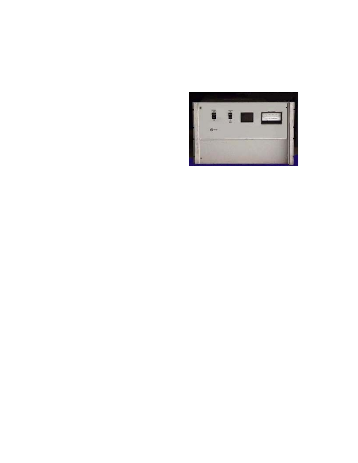
Varian Medium Power Amplifier 6900G Series
Features
o 1.0 to 18 GHz
o 100 and 200 Watt Models
o Octave Bandwidths or Greater
o Optional GPIB Control
Description
For test and measurement applications that require RF power of 100 or
200 watts, Varian offers the 6900G Series power amplifier. For testing on
antenna ranges, in EMC chambers or on a test bench. Varian provides
equipment built with quality and reliability that you can trust.
The 6900G series amplifiers are constructed with proven reliable metalceramic traveling wave tubes (TWTs) built to provide dependable service
for a wide range of applications. The power supply for the 6900G series is
a reliable, high efficiency switching design. Combined with Varian TWTs,
the 6900G series amplifier provides the industry standard for
dependability.
The 6900G series TWT amplifier has a full line of standardized options
including remote control input isolators and output VSWR protection. For
ATE applications, IEEE 488 bus controllable amplifiers are available.
More than a thousand Varian 6900G series amplifiers are used throughout
the world, performing over a wide range of specifications, in a variety of
environmental and operating conditions.
Varian 6900G series TWT amplifiers are manufactured with components
that match the high quality of all Varian amplifiers and are backed by the
worldwide Varian product support network that includes a 24-hour hot-line.
Quality, reliability and product support are integral parts of your Varian
power amplifier.
1
Page 2

Selection Guide
Model #
VZU-6992G5 100 12.4-18 37
VZM-6992G6 100 9-17 37
VZL-6943G5 200 1-2 30
VZS-6953G5 200 2-4 37
VZC-6963G5 200 4-8 37
VZX-6983G5 200 8-12.4 35
VZU-6993G7 200 12.4-18 35
VZM-6993G7 200 8-18 35
Power
(Watts)
Specifications
Frequency Range: 1 to 18 GHz (see selection guide)
Rated Output Power: 100 or 200 Watts CW. Saturated output power generally
exceeds rated power by 1.5 to 3 db near band center.
The insertion loss of options added at the output will
reduce power delivered to the output connector.
30 to 37 dB at rated power (see selection guide).
Typical gain is 4 dB above spec at band edges and 10
dB above spec at band center. Gain is reduced by all
microwave options (see option L for higher gain.
Gain Stability: ±0.25 dB/day at constant drive and temperature.
Gain Variation: 10 dB peak-to-peak typical across all bands except 8-18
GHz where it is 15 dB typical.
Input/Output impedance: 50 Ohms nominal
VSWR: Input: 2.0:1 typical
Output: 2.0:1 typical
Load: 1.5:1 max for full spec. Compliance;
2.0:1 max for no damage without option M. Any
value with option M
Noise & Spurious: -50 dBc typical excluding harmonics.
Residual AM: -40 dBc up to 10 KHz
-20 (1+ log f) dBc, 10 to 500 KHz
-80 dBc above 500 KHz
Residual FM: Less than 4 KHz peak-to-peak for 0 to 5 MHz from
carrier.
AM/PM Conversion: 2.5-degrees/dB max at 6 dB below rated output power.
Noise figure: 40 dB max, 20 dB with option L
Harmonic Content: -3dBc typical at lower band edge decreasing to –15 dBc
typical at upper band edge.
Freq.
(GHz)
Gain
(dB)
2
Page 3

Meters, Monitors,
•
Controls & Indicators
Meters: Helix Current
Filament Elapsed Time (Option H)
Monitors: RF Output Sample (Option E)
Controls: Mains Power ON/OFF
High Voltage ON/OFF – Fault Reset
Local/Remote (Option G)
RF Attenuator (Option B)
Indicators:
• Mains Power ON
• Filament Time Delay • TWT Over-temperature
• Standby • External Interlock Fault (option G)
• High Voltage On • Remote Control (option G)
• Summary Fault • Reflected Power Fault (option M)
• Cover Interlock Fault • Power Supply Fault
Helix Current Fault
Mechanical &
Environmental
Ambient Temperature: 0 to 50°C
Relative Humidity: to 95% non Condensing
Altitude: to 10,000 feet max. Derate temperature 2°C/1,000 feet
above 4,000 feet.
Shock & Vibration: As normally encountered in a protected engineering
laboratory environment.
Cooling: Forced air with integral blower, air intake and exhaust in
rear.
RF Connectors: Type N(female), on rear panel (front panel w/Option j)
Frequency (GHz) Type
1-2 N (female)
2-4 N (female)
4-8 N (female)
8-12.4 UG-39/U (WR-90)
12.4-18 UG-419/U (WR-62)
8-18 MIL-F-39000/3-74 (WRD-
750)
Prime Power: 115 Vac ±10%, 47-63Hz, single phase
230 Vac (option K)
Power Consumption: 1900 Watts for 100W TWT models
2400 Watts for 200W TWT models
Dimensions: 12.25”H x 19”W x 24”D
Weight: 195 Lbs./ 89 Kg.
3
 Loading...