

Page 1
FREQUENCY SYNTHESIZERS, SIGNAL GENERAT ORS
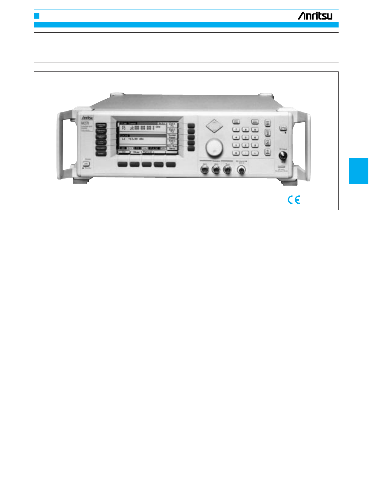
SYNTHESIZED SWEEP/SIGNAL GENERA TOR
69A, 68B series
10 MHz to 65 GHz
5
A microwave synthesizer for any application
Anritsu Wiltron’s El Toro microwave synthesizers present 80 models,
providing you the right synthesizer for your LO duty, component
analysis, signal simulation, or A.T.E. applications. The 69A family,
with the lowest Single Sideband (SSB) phase noise available, provides the ultimate performance at moderate cost, and includes models with unprecedented 0.01 to 65 GHz frequency coverage.
Features
•120 models for perfect fit to any application
•
Ultra-low SSB phase noise; –100 dBc at 10 kHz offset from 10 GHz
•0.01 to 65 GHz frequency coverage in a single coaxial output
•Waveguide extensions to 110 GHz
•Economical upgrades
•+17 dBm maximum power, –125 dBm minimum power
•Internal AM, FM, øM, pulse modulation
•User down-loaded complex modulation
Applications
•CW stimulus
The 69000A/68000B Synthesized CW Generators feature 10 MHz to
65 GHz frequency coverage. CW or step sweep, low SSB phase
noise and spurious signals, output levels to +17 dBm, and optional
0.1 Hz resolution combine to make these sources ideal for local oscillator replacement applications. To meet requirements that expand
over time, economical upgrades are available to any higher performing model. For the most demanding CW requirements, the 69000A
and 68000B provide the ultimate in performance.
GPIB
•Swept measurements
The 69100A/68000B Synthesized Sweep Generators feature 10
MHz to 65 GHz analog, step, and manual sweep capability. Output
levels to +17 dBm and optional 0.1 Hz resolution are available at
prices comparable to CW only sources. To meet requirements that
expand over time, economical upgrades are available to any higher
performing model. Features, performance, and value combine to
make the 69100A and 68100B the optimum sources for your netw ork
analysis and swept A.T.E. source applications.
•
High performance modulation for signal simulation requirements
The 69200A/68200B Synthesized Signal Generators provide AM
and FM via external modulating signals or internal arbitrary waveform generators. The internal generators offer 7 modulating waveforms, including Gaussian noise, as well as user-defined arbitrary
wavef orms. Pulse modulation parameters can be set externally or by
the internal pulse generator. Doublet, triplet, or quadruplet pulses
make RADAR blind spot testing easy. Simultaneous synchronized
modulations let you set complex signal scenarios across the entire
10 MHz to 65 GHz frequency range.
•Complete synthesized modulation and sweep capabilities for
any signal requirement
The 69300A/68300B Synthesized Sweep/Signal Generators provide
all the capabilities of our CW generators, sweep generators , and signal generators in a single package. The 69300A is the highest performance universal synthesized signal generator available today.
227
Page 2
FREQUENCY SYNTHESIZERS, SIGNAL GENERAT ORS
Comprehensive Int/Ext
modulation?
Comprehensive Int/Ext
modulation?
Analog sweep
capability?
Analog sweep
capability?
Analog sweep
capability?
Analog sweep
capability?
Ultra low
phase noise?
68000B 68100B 68200B 68300B 69000B 69100B 69200B 69300B
No
No
No No No
No
No
Yes
Yes
YesYesYesYes
Yes
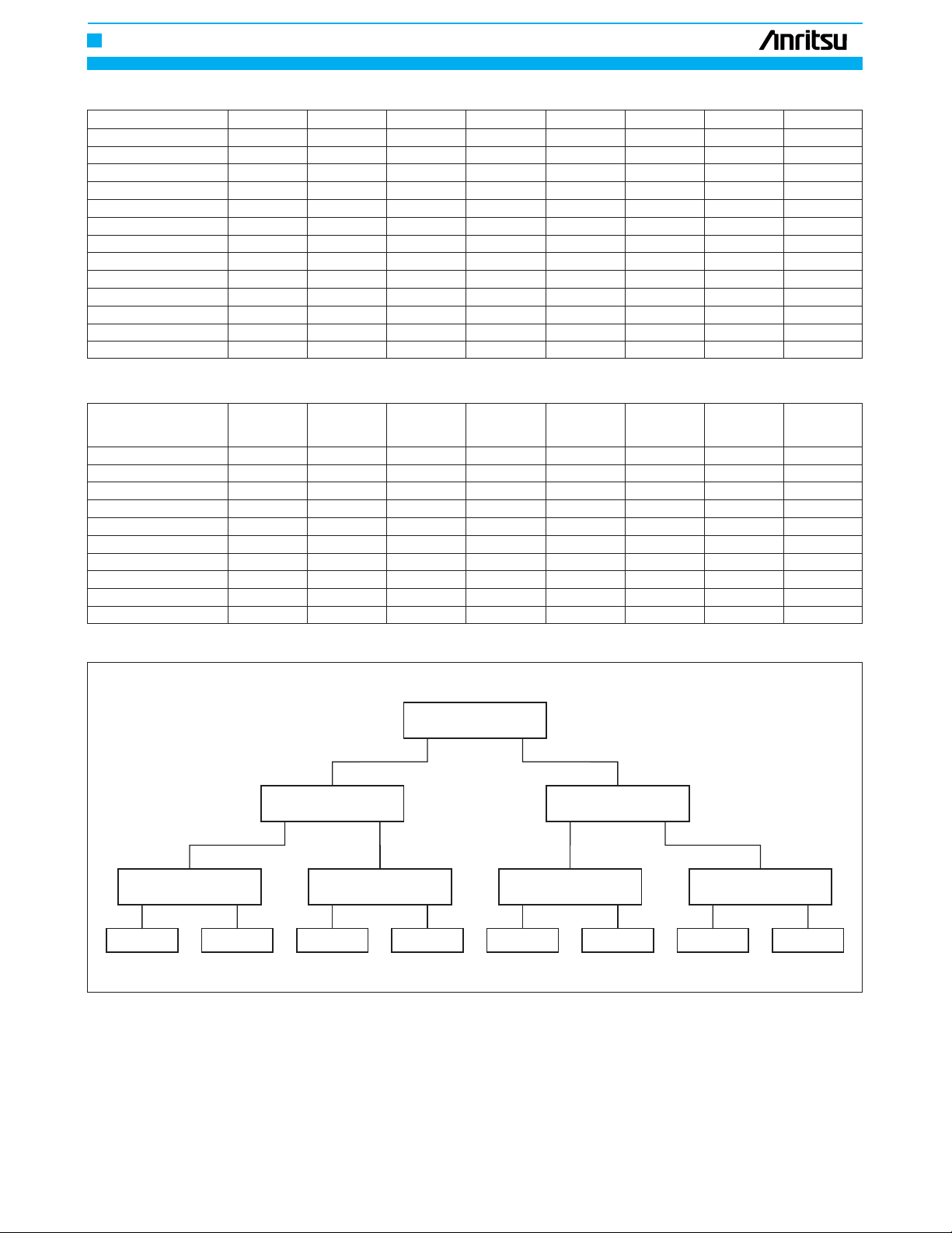
El Toro synthesizers product selection table
Model 68000B 69000A 68100B 69100A 68200B 69200A 68300B 69300A
Ultra low ø noise √√√√
Step sweep √√√√√√√√
Analog sweep √√ √√
Power sweep √√√√√√√√
Alternate sweep √√√√√√√√
Master/slave √√√√√√√√
AM Ext Ext Int/Ext Int/Ext Int/Ext Int/Ext
FM Ext Ext Int/Ext Int/Ext Int/Ext Int/Ext
øM Opt. 6 Opt. 6 Opt. 6 Opt. 6
Pulse modulation Ext Ext Int/Ext Int/Ext Int/Ext Int/Ext
AM scan (1 to 20 GHz) Opt. 20 Opt. 20 Opt. 20 Opt. 20
Internal power meter Opt. 8 Opt. 8 Opt. 8 Opt. 8
360B SS Mode √√√√√√
El Toro family model summary
68000B 69000A
CW CW Sweep Sweep Signal Signal Sweep/Signal Sweep/Signal
Generator Generator Generator Generator Generator Generator Generator Generator
2 to 20 GHz 68037B 69037A 68137B 69137A 68237B 69237A 68337B 69337A
0.5 to 20 GHz 68045B 69045A 68145B 69145A 68245B 69245A 68345B 69345A
0.01 to 20 GHz 68047B 69047A 68147B 69147A 68247B 69247A 68347B 69347A
2 to 26.5 GHz 68053B 69053A 68153B 69153A 68253B 69253A 68353B 69353A
0.01 to 26.5 GHz 68059B 69059A 68159B 69159A 68259B 69259A 68359B 69359A
2 to 40 GHz 68063B 69063A 68163B 69163A 68259B 69263A 68363B 69363A
0.01 to 40 GHz 68069B 69069A 68169B 69169A 68265B 69269A 68369B 69369A
0.01 to 50 GHz 68077B 69077A 68177B 69177A 68277B 69277A 68377B 69377A
0.01 to 60 GHz 68087B 69087A 68187B 69187A 68285B 69287A 68377B 69387A
0.01 to 65 GHz 68097B 69097A 68197B 69197A 68297B 69297A 68395B 69397A
1: Complete performance specifications for 69A synthesizers are available in the 69A Series Synthesizers Technical Data Sheet, part number 11410-00175
*
1
*
68100B 69100A
1
*
68200B 69200A
1
*
68300B 69300A
1
*
228
Page 3
FREQUENCY SYNTHESIZERS, SIGNAL GENERAT ORS
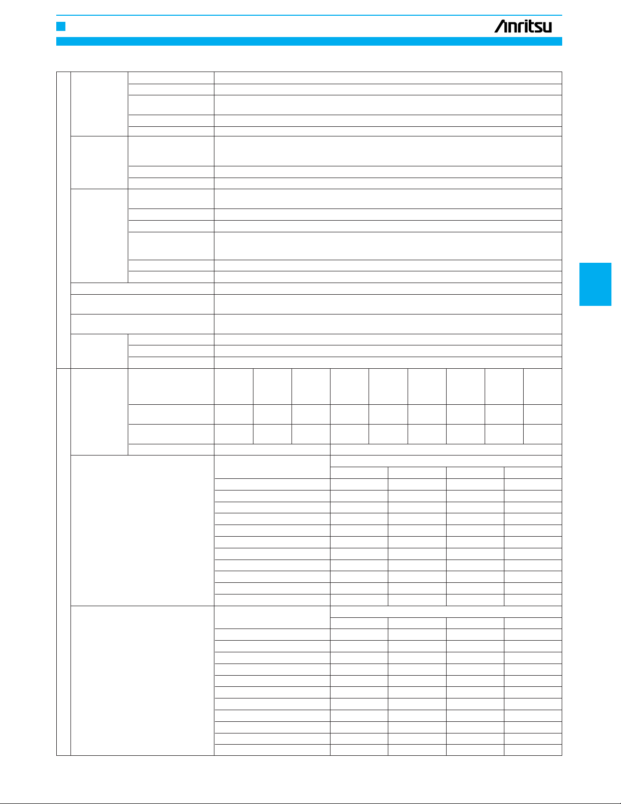
Specifications
Output Twenty independent, presettable CW frequencies (F0 to F9 and M0 to M9)
Accuracy Same as internal or external 10 MHz time base
CW mode
Analog sweep
mode (69100A,
69300A) Accuracy The lesser of ±30 MHz or (±2 MHz widths) for sweep speeds of ≤50 MHz/ms
Phase-locked
Frequency
step sweep Number of steps: Variable from 1 to 10000
mode Steps Step size: 1 kHz (0.1 Hz with Option 11) to the full frequency range of the instrument. (If the step size does
Alternate sweep mode
Manual sweep mode
Programmable frequency agility
Markers Video markers +5 V or –5 V marker output, selectable. AUX I/O connector, rear panel
Spurious
signals
Single-sideband phase noise, 69XXXA 6 GHz –78 –100 –100 –105
1
*
(dBc/Hz) 10 GHz –74 –98 –100 –105
Spectral purity
Single-sideband phase noise, 68XXXB 6 GHz –78 –88 –86 –102
(dBc/Hz) 10 GHz –73 –86 –83 –102
Internal time base With aging: <2 x 10
stability With temperature: <2 x 10
Resolution 1 kHz (0.1 Hz with Option 11)
Switching time <40 ms to be within 1 kHz of final frequency (typical maximum)
Sweep width stop and bandswitching frequencies are phase-lock-corrected during sweep. For ≤100 MHz widths, the
Sweep time range 30 ms to 99 seconds
Sweep width
Accuracy Same as internal or external 10 MHz time base
Resolution (Min. step size)
Dwell time per step Variable from 1 ms to 99 seconds
Switching time <15 ms +1 ms/GHz step size or <40 ms, whichever is less (typical max.)
Setting Up to 20 independent, settable markers (F0 to F9 and M0 to M9)
Intensity markers Produces an intensified dot on trace, obtained by momentary dwell in RF sweep
Frequency range
Harmonic and harmonic
related
Harmonic and harmonic
2
*
related
Nonharmonic <–40 dBc <–60 dBc
Independently selected from 1 MHz to full range continuous sweep. For *100 MHz sweep width, the start,
center frequency is phase-lock-corrected.
Independently selected, 1 kHz (0.1 Hz with Option 11) to full range. Every frequency step in sweep range
is phase-locked.
1 kHz (0.1 Hz with Option 11)
Sweeps alternately between any two sweep ranges. Each sweep range may be associated with a different power level.
Provides stepped, phase-locked adjustment of frequency between sweep limits. User-selectable number of
steps or step size.
Under GPIB control, up to 1000 non-sequential frequencies can be stored and then addressed as a
phase-locked step sweep. Data is stored in volatile memory.
500 MHz 10 to >50 MHz >2 to ≤20 >40 to >45 to
to ≤2.2 50 MHz to ≤2 GHz GHz (2.2 to >20 to >40 to >40 to ≤45 GHz ≤65 GHz
GHz (500 (10 MHz (10 MHz 500 MHz ≤40 GHz ≤50 GHz ≤60 GHz (65 GHz (65 GHz
MHz units) units) units) units) units) units)
<–50 dBc <–30 dBc <–40 dBc <–60 dBc <–40 dBc – – – –
<–50 dBc <–30 dBc <–40 dBc <–50 dBc <–40 dBc <–40 dBc <–30 dBc <–25 dBc <–30 dBc
0.6 GHz (69XX5A) –92 –112 –112 –117
0.6 GHz –80 –98 –100 –102
2 GHz (69XX5B) –86 –106 –106 –111
2 GHz –80 –100 –100 –105
20 GHz –66 –95 –100 –102
26.5 GHz –63 –91 –94 –96
40 GHz –60 –89 –94 –96
50 GHz –57 –83 –88 –90
65 GHz –54 –83 –88 –90
0.6 GHz (68XX5B) –87 –100 –98 –115
0.6 GHz –77 –88 –86 –100
2 GHz (68XX5B) –81 –94 –92 –109
2 GHz –80 –88 –86 –102
20 GHz –66 –78 –78 –100
26.5 GHz –63 –78 –76 –96
40 GHz –60 –75 –72 –94
50 GHz –54 –69 –66 –88
65 GHz –54 –69 –64 –88
–8
/day (<5 x 10
not divide into the selected frequency range, the last step is truncated.)
69XXXA
68XXXB
–10
–8
/day with Option 16)
/˚C over 0˚C(<2 x 10
100 Hz 1 kHz 10 kHz 100 kHz
100 Hz 1 kHz 10 kHz 100 kHz
–10
/˚C with Option 16)
Offset from carrier
Offset from carrier
Continued on next page
5
229
Page 4

FREQUENCY SYNTHESIZERS, SIGNAL GENERAT ORS
Models Frequency range Output power Output power with step attenuator
6XX37 ≥2 to ≤20 GHz +13 dBm +11 dBm
6XX45 ≥0.5 to ≤20 GHz +13 dBm +11 dBm
6XX47 ≥0.01 to ≤20 GHz +13 dBm +11 dBm
6XX53
6XX59 ≥2 to ≤20 GHz +9 dBm +7 dBm
6XX63
6XX69 ≥2 to ≤20 GHz +9 dBm +7 dBm
6XX77
6XX87 >20 to ≤40 GHz +2.5 dBm 0 dBm
Output power
6XX97 >20 to ≤40 GHz +2.5 dBm –
6XX37 ≥2 to ≤20 GHz +17 dBm +15 dBm
6XX45
6XX47
With Option 15
(high power) ≥20 to ≤26.5 GHz +10 dBm +7.5 dBm
installed
6XX53
6XX59 ≥2 to ≤20 GHz +13 dBm +11 dBm
6XX63
6XX69
≥2 to ≤20 GHz +9 dBm +7 dBm
>20 to ≤26.5 GHz +6 dBm +3.5 dBm
≥0.01 to <2 GHz +13 dBm +11 dBm
>20 to ≤26.5 GHz +6 dBm +3.5 dBm
≥2 to ≤20 GHz +9 dBm +7 dBm
>20 to ≤40 GHz +6 dBm +3 dBm
≥0.01 to <2 GHz +13 dBm +11 dBm
>20 to ≤40 GHz +6 dBm +3 dBm
≥0.01 to <2 GHz +12 dBm +10 dBm
≥2 to ≤20 GHz +10 dBm +8.5 dBm
>20 to ≤40 GHz +2.5 dBm 0 dBm
>40 to ≤50 GHz +2.5 dBm –1 dBm
≥0.01 to <2 GHz +12 dBm +10 dBm
≥2 to ≤20 GHz +10 dBm +8.5 dBm
>40 to ≤50 GHz +2 dBm –1.5 dBm
>50 to ≤60 GHz +2 dBm –2 dBm
≥0.01 to <2 GHz +12 dBm
≥2 to ≤20 GHz +10 dBm
>40 to ≤50 GHz 0 dBm
>50 to ≤65 GHz –2 dBm
≥0.5 to ≤2.2 GHz +13 dBm +11 dBm
>2.2 to ≤20 GHz +17 dBm +15 dBm
≥0.01 to <2 GHz +13 dBm +11 dBm
≥2 to ≤20 GHz +17 dBm +15 dBm
≥2 to <20 GHz +13 dBm +11 dBm
≥0.01 to <2 GHz +13 dBm +11 dBm
>20 to ≤26.5 GHz +10 dBm +7.5 dBm
≥2 to ≤20 GHz +13 dBm +11 dBm
>20 to ≤40 GHz +6 dBm +3 dBm
≥0.01 to ≤20 GHz +13 dBm +11 dBm
>20 to ≤40 GHz +6 dBm +3 dBm
Continued on next page
230
Page 5

FREQUENCY SYNTHESIZERS, SIGNAL GENERAT ORS
Levelled output
power range
Unleveled
output power
range (typical)
Power level
switching time
(to within specified accuracy)
Accuracy and
flatness (step
sweep and CW
modes)
RF output
Output power resolution 0.01 dB
Level offset Offsets the displayed power level to establish a new reference level
CW power Accuracy Same as CW power accuracy
sweep
Sweep frequency/step power
Amplitude Linear AM: Continuously variable from 0 to 100%/V
modulation
Frequency
modulation Narrow mode: ±10 MHz, DC to 500 kHz rates
69100A/68100B modulation
Square wave
modulation
Amplitude
modulation
69200A/69300A/68200B/68300B
modulation
Without an attenuator
With an attenuator
Without an attenuator >40 dB below max power
With an attenuator >130 dB below max power
Without change in step
attenuator
With change in step
attenuator
Accuracy 25 to 60 dB ±2.0 dB ±1.0 dB ±1.0 dB ±1.5 dB ±3.5 dB –
Flatness 25 to 60 dB ±2.0 dB ±0.8 dB ±0.8 dB ±1.1 dB ±3.1 dB –
Range Sweeps between any two power levels at a single CW frequency
Resolution 0.01 dB/step
Step size User-controlled, 0.01 dB to the full power range of the instrument
Step dwell time
External AM input
AM sensitivity
AM depth 0 to 90% linear, 20 dB log (typical with RF level at 6 dB below maximum rated output)
AM bandwidth (3 dB) DC to 50 kHz minimum (DC to 100 kHz typical)
Maximum input ±1 V
External FM input Front or rear panel BNC, 50 Ω or 600 Ω input impedance. All options selectable from modulation menu
FM sensitivity
Deviation Wide mode: ±100 MHz, DC to 100 Hz rates
On/off ratio >50 dB
Rise/fall time <1 µs typical
Internal square wave
generator
4
*
External input
External AM input
AM sensitivity
AM depth (typical) 0 to 90% linear; 20 dB log
AM bandwidth DC to 50 kHz minimum (DC to 100 kHz typical)
*5Flatness ±0.3 dB (DC to 10 kHz rates)
Accuracy ±5%
Distortion <5% typical
Incidental phase
modulation
Maximum input ±1 V
Maximum levelled power to –15 dBm (–20 dBm typical). For units with Option 15 installed, minimum
settable power is –5 dBm (–10 dBm typical).
Maximum levelled power to –115 dBm (–120 dBm typical). For units with upper limit ≥50 GHz and units with
Option 15 installed, minimum settable power is –105 dBm (–110 dBm typical).
<1 ms typical
<20 ms typical
Attenuation
below max
power
0 to 25 dB ±2.0 dB ±1.0 dB ±1.0 dB ±1.5 dB ±1.5 dB ±1.5 dB
>60 dB ±2.0 dB ±1.0 dB ±1.0 dB ±2.5 dB ±3.5 dB –
0 to 25 dB ±2.0 dB ±0.8 dB ±0.8 dB ±1.1 dB ±1.1 dB ±1.1 dB
>60 dB ±2.0 dB ±0.8 dB ±0.8 dB ±2.1 dB ±3.1 dB –
Variable from 1 ms to 99 seconds. If the sweep crosses a step attenuator setting, there will be a sweep
dwell of approximately 20 ms to allow setting of the step attenuator.
A power level step occurs after each frequency sweep. Power level remains constant for length of time
required to complete each sweep.
Log AM or linear AM input, front or rear-panel BNC, 50 Ω or 600 Ω input impedance All options selectable
from modulation menu
Log AM: Continuously variable from 0 to 25 dB/V
Variable from ±10 kHz/V to ±20 MHz/V (narrow FM modes) or from ±100 kHz/V to ±100 MHz/V (wide FM mode)
Locked mode: The lesser of ±10 MHz or rate x 300, 1 to 500 kHz rates
Four square wave signals (400 Hz, 1 kHz, 7.8125 kHz, and 27.8 kHz), selectable from modulation menu
Accuracy: Same as internal or external 10 MHz time base
Square wave symmetry: 50% ±5% at all power levels
Front or rear-panel BNC, selectable from modulation menu
Drive level: TTL compatible input
Minimum pulse width: >5 µs
Input logic: Positive-true or negative-true BNC, selectable from modulation menu
Log AM or linear AM input, front or rear-panel BNC, 50 Ω or 600 Ω input impedance
All options selectable from modulation menu
Log AM: Continuously variable from 0 to 25 dB per volt
Linear AM: Continuously variable from 0 to 100% per volt
<0.2 radians (30% depth, 10 kHz rate)
0.01 to
0.05 GHz
0.05 to 20 GHz
20 to 40 GHz 40 to 50 GHz 50 to 60 GHz 60 to 65 GHz
3
*
Continued on next page
5
231
Page 6

FREQUENCY SYNTHESIZERS, SIGNAL GENERAT ORS
Waveforms
Internal AM
generator
Frequency
modulation
Internal FM
generator
69200A/69300A/68200B/68300B modulation
Phase 100 kHz rate) Wide mode (DC to 500 kHz rates): ±1 dB
modulation
(øM, Option 6)
Internal øM
generator
(shares the
internal FM
generator)
Pulse
modulation
Rate 0.1 Hz to 1 MHz sinusoidal, 0.1 Hz to 100 kHz squarewave, triangle, ramps
Resolution 0.1 Hz
Accuracy Same as instrument timebase
Output BNC connector, rear panel
External FM input
FM sensitivity
Deviation
FM bandwidth (3 dB)
Flatness ±1 dB (10 kHz to 1 MHz rates)
Accuracy 10% (5% typical, ±200 kHz deviation, 100 kHz rate)
Incidental AM <2% (±1 MHz deviation, 1 MHz rate)
Harmonic distortion <1% (±1 MHz deviation, 10 kHz rate)
Maximum input ±1 V
Waveforms
Rate 0.1 Hz to 1 MHz sinusoidal, 0.1 Hz to 100 kHz squarewave, triangle, ramps
Resolution 0.1 Hz
Accuracy Same as instrument timebase
Output BNC connector, rear panel
øM deviation
øM bandwidth (3 dB, Narrow mode: DC to 10 MHz
relative to 100 kHz rate) Wide mode: DC to 1 MHz
øM flatness (relative to Narrow mode (DC to 1 MHz rates): ±1 dB
øM accuracy 10% (at 100 kHz sine wave)
External øM input
External øM sensitivity volt (wide øM mode), selectable from modulation menu. For 6XXX5 units, maximum sensitivity is divided
External øM maximum
input
Waveforms
Rate 0.1 Hz to 1 MHz for sine wave, 0.1 Hz to 100 kHz for other waveforms
Resolution 0.1 Hz
Accuracy Same as instrument timebase
Output BNC connector, rear panel
On/off ratio >80 dB
Rise/fall time (10 to 90%)
Minimum levelled pulse
width
*6Minimum unleveled
pulse width
Pulse overshoot <10% (for 60 and 65 GHz units, overshoot from 40 to 60 GHz is 20% typical)
Level accuracy relative
to CW
Sinusoid, squarewave, triangle, positive ramp, negative ramp, Gaussian noise, uniform noise,
user defined (Option 10)
Front or rear panel BNC, 50 Ω or 600 Ω input impedance
All options selectable from modulation menu
Continuously variable from ±10 kHz per volt to ±20 MHz per volt (locked, locked low noise and unlocked
narrow modes), or ±100 kHz per volt to ±100 MHz per volt (unlocked wide mode)
For 500 MHz units, maximum sensitivity is divided by 2 from 1 to 2.2 GHz and is divided by 4 from 500
MHz to 1 GHz.
Unlocked wide: ±100 MHz, DC to 100 Hz rates
Unlocked narrow: ±10 MHz, DC to 8 MHz rates
Locked: The lesser of ±10 MHz or rate x 300, 1 kHz to 8 MHz rates
Locked low noise: The lesser of ±10 MHz or rate x 3, 50 kHz to 8 MHz rates
Unlocked wide: DC to 100 Hz
Unlocked narrow: DC to 10 MHz
Locked: 1 kHz to 10 MHz
Locked low noise: 30 kHz to 10 MHz
Sinusoid, squarewave, triangle, positive ramp, negative ramp, Gaussian noise, uniform noise, user defined
(Option 10)
Narrow mode (DC to 8 MHz rates): The lesser of ±3 radians or ±5 MHz/rate
Wide mode (DC to 1 MHz rates):
The lesser of ±400 radians or ±10 MHz/rate. For 6XXX5 units, maximum deviation is divided by 2 from
>1.0 to ≤2.2 GHz and is divided by 4 from ≥0.5 to ≤1.0 GHz.
Front or rear panel BNC (shares the FM input), 50 Ω or 600 Ω input impedance. All options selectable from
modulation menu. Shares connectors with FM.
Continuously variable from ±0.0025 to ±5 radians per volt (narrow øM mode) or ±0.25 to ±500 radians per
by 2 from >1 to ≤2.2 GHz and is divided by 4 from ≥0.5 to <1 GHz.
±1 V
Sine, square, triangle, positive ramp, negative ramp, Gaussian noise, uniform noise, user defined (option 10)
<10 ns (<5 ns typical). (for 6XXX5 units, rise/fall time below 1 GHz is 15 ns)
<100 ns (≥2 GHz), <1 µs (<2 GHz)
<10 ns
±0.5 dB (≥1 µs pulse width), ±1.0 dB (<1 µs pulse width) 100 Hz to 1 MHz PRF
Continued on next page
232
Page 7

FREQUENCY SYNTHESIZERS, SIGNAL GENERAT ORS
Video feedthrough <±10 mV, ≥2 GHz
Pulse width compression <8 ns typical
Pulse
modulation
Internal pulse Variable
generator delay
69200A/69300A modulation
SCAN
modulator
(Option 20,
6X237, 6X245,
6X247, 6X337,
6X345 and
6X347 only)
GPIB address Selectable from a system menu
8
*
IEEE-488 interface function subset SH1, AH1, T6, L4, SR1, RL1, PP1, DC1, DT1, C0, C1, C2, C3, C28, E2
Emulations signal sources. When emulating another signal source, the instrument is limited to the capabilities,
Remote
operation
Stored setups allows saving and recalling of instrument setups. Whenever the instrument is turned on, control settings
Memory sequencing input Accepts a TTL low-level signal to sequence through nine stored setups. AUX I/O connector, rear panel
Self-test
Secure mode
Reset
Master/slave operation controls the other via AUX I/O and SERIAL I/O connections. Requires MASTER/SAVE interface cable set
General
User level flatness correction
Warm up time (standard time base) From standby: 30 minutes From cold start (0<): 120 hours to achieve <2 x 10⁻⁸/day frequency stability
Warm up time (option 16 time base) From standby: 30 minutes From cold start (0<): 72 hours to achieve <5 x 10
Power 90 to 132 Vac or 180 to 264 Vac, 49 to 440 Hz, ≤400 VA
Standby
Dimensions and mass 429 (W) x 133 (H) x 597 (D) mm [5.25 (H) x 16.875 (W) x 23.5 (D) in.], ≤23 kg (50 lb)
RF output connector Type K female (≤40 GHz models), Type V female (>40 GHz models)
1: All specifications apply to the phase-locked CW and step sweep modes at the lesser of +10 dBm output or maximum specified levelled output power, unless
*
otherwise noted.
2: >40 GHz units and units with Option 15 at maximum specified levelled output power
*
3: For 6x1x5 units, maximum sensitivity is divided by 2 from 1 to 2.2 GHz and is divided by 4 from 500 MHz to 1 GHz.
*
4: The RF output can be pulse modulated via an external modulating signal or an internal square wave generator
*
5: All amplitude modulation specifications apply at 50% depth, 1 kHz rate, with RF level set 6 dB below maximum specified levelled output power, unless oth-
*
er-wise noted
6: All pulse modulation specifications apply at maximum specified levelled output power, unless otherwise noted
*
7: Maximum attenuation = attenuation ±flatness
*
8: All instrument functions, settings, and operating modes (except for power on/standby) are controllable using commands sent from an external computer via
*
the GPIB (IEEE-488 interface bus).
Pulse delay (typical) Triggered mode: 100 ns
6
*
PRF range DC to 10 MHz unleveled, 100 Hz to 5 MHz levelled
External input Drive level: TTL compatible input
Frequency
(selectable clock rate)
Pulse width 25 ns to 419 ms 100 ns to 1.6 s
Pulse period 250 ns to 419 ms 600 ns to 1.6 s
Singlet 0 to 419 ms 0 to 1.6 s
Doublet 100 ns to 419 ms 300 ns to 1.6 s
Triplet 100 ns to 419 ms 300 ns to 1.6 s
Quadruplet 100 ns to 419 ms 300 ns to 1.6 s
Resolution 25 ns 100 ns
Modes Free-run, triggered, gated, delayed, singlet, doublet, triplet, quadruplet
Accuracy 10 ns (5 ns typical)
Outputs Video pulse and sync out, rear-panel BNC connectors
Frequency range 1 to 20 GHz
Attenuation range
Flatness ±2 dB (0 to 40 dB), ±3.5 dB (40 to 60 dB)
Step response <1 µs
Sensitivity –10 dB/V
Insertion loss
(when engaged)
Input Rear-panel BNC (f) connector
External mode: 50 ns
Triggered with delay mode: 200 ns
Front or rear-panel BNC, selectable from modulation menu
Input logic: Positive-true or negative-true, selectable from modulation menu
40 MHz 10 MHz
7
*
0 to 60 dB
<6 dB (1 to 18 GHz), <8 dB (18 to 20 GHz)
The instrument responds to the published GPIB commands and responses of the models 6XX00-series
mnemonics, and parameter resolutions of the emulated instrument.
Stores front panel settings and nine additional front-panel setups in a non-volatile RAM. A system menu
come on at the same functions and values existing when the instrument was turned off.
Instrument self-test is performed when SELF TEST soft-key is selected. If an error is detected, an error
message is displayed in a window on the LCD identifying the probable cause.
Disables all frequency, power level, and modulation state displays. Stored setups saved in secure mode
remain secured when recalled. Mode selectable from a system menu and GPIB
Returns instrument parameters to predefined default states or values. Any pending GPIB I/O is aborted.
Selectable from the system menu
Allows two 68X00B output signals to be swept with a user-selected frequency offset. One 68X00B unit
(part no. ND36329)
Allows user to calibrate out path loss due to external switching and cables via entered power table from a
GPIB power meter or calculated data. When user level correction is activated, entered power levels are
delivered at the point where calibration was performed. Supported power meters are Anritsu ML4803A
and HP437B, 438A, and 70100A. Five user tables are available at up to 801 points/table
–10
/day frequency stability
With ac line power connected, unit is placed in standby when front panel power switch is released from
the OPERATE position
5
233
Page 8

FREQUENCY SYNTHESIZERS, SIGNAL GENERAT ORS
Ordering Information
Please specify model/order number, name, and quantity when ordering.
Model/Order
No.
Name
Main frame
69037A Ultra Low Noise Synthesized CW Generator (2 to 20 GHz)
69045A
69047A
69053A
69059A Ultra Low Noise Synthesized CW Generator
69063A
69069A
69077A
69087A
69097A
69137A
69145A Ultra Low Noise Synthesized Sweep Generator
69147A Ultra Low Noise Synthesized Sweep Generator
69153A
69159A Ultra Low Noise Synthesized Sweep Generator
69163A
69169A Ultra Low Noise Synthesized Sweep Generator
69177A Ultra Low Noise Synthesized Sweep Generator
69187A Ultra Low Noise Synthesized Sweep Generator
69197A Ultra Low Noise Synthesized Sweep Generator
69237A
69245A Ultra Low Noise Synthesized Signal Generator
69247A Ultra Low Noise Synthesized Signal Generator
69253A
69259A Ultra Low Noise Synthesized Signal Generator
69263A
69269A Ultra Low Noise Synthesized Signal Generator
69277A Ultra Low Noise Synthesized Signal Generator
69287A Ultra Low Noise Synthesized Signal Generator
69297A Ultra Low Noise Synthesized Signal Generator
69337A Ultra Low Noise Synthesized Sweep/Signal Generator
69345A Ultra Low Noise Synthesized Sweep/Signal Generator
69347A Ultra Low Noise Synthesized Sweep/Signal Generator
69353A Ultra Low Noise Synthesized Sweep/Signal Generator
69359A Ultra Low Noise Synthesized Sweep/Signal Generator
69363A Ultra Low Noise Synthesized Sweep/Signal Generator
69369A Ultra Low Noise Synthesized Sweep/Signal Generator
69377A Ultra Low Noise Synthesized Sweep/Signal Generator
69387A Ultra Low Noise Synthesized Sweep/Signal Generator
69397A Ultra Low Noise Synthesized Sweep/Signal Generator
Ultra Low Noise Synthesized CW Generator (500 MHz to 20 GHz)
Ultra Low Noise Synthesized CW Generator (10 MHz to 20 GHz)
Ultra Low Noise Synthesized CW Generator (2 to 26.5 GHz)
1
(10 MHz to 26.5 GHz)
Ultra Low Noise Synthesized CW Generator (2 to 40 GHz)
*
*
Ultra Low Noise Synthesized CW Generator (10 MHz to 40 GHz)
Ultra Low Noise Synthesized CW Generator (10 MHz to 50 GHz)
Ultra Low Noise Synthesized CW Generator (10 MHz to 60 GHz)
Ultra Low Noise Synthesized CW Generator (10 MHz to 65 GHz)
Ultra Low Noise Synthesized Sweep Generator (2 to 20 GHz)
1
(500 MHz to 20 GHz)
(10 MHz to 20 GHz)
Ultra Low Noise Synthesized Sweep Generator (2 to 26.5 GHz)
(10 MHz to 26.5 GHz)
Ultra Low Noise Synthesized Sweep Generator (2 to 40 GHz)
(10 MHz to 40 GHz)
(10 MHz to 50 GHz)
(10 MHz to 60 GHz)
(10 MHz to 65 GHz)
*
1
*
1
*
1
*
2
*
2
*
2
*
*
Ultra Low Noise Synthesized Signal Generator (2 to 20 GHz)
1
(500 MHz to 20 GHz)
(10 MHz to 20 GHz)
Ultra Low Noise Synthesized Signal Generator (2 to 26.5 GHz)
(10 MHz to 26.5 GHz)
Ultra Low Noise Synthesized Signal Generator (2 to 40 GHz)
(10 MHz to 40 GHz)
(10 MHz to 50 GHz)
(10 MHz to 60 GHz)
(10 MHz to 65 GHz)
(2 to 20 GHz)
(500 MHz to 20 GHz)
(10 MHz to 20 GHz)
(2 to 26.5 GHz)
(10 MHz to 26.5 GHz)
(2 to 40 GHz)
(10 MHz to 40 GHz)
(10 MHz to 50 GHz)
(10 MHz to 60 GHz)
(10 MHz to 65 GHz)
*
1
*
1
*
1
*
2
*
2
*
2
*
1
*
1
*
1
*
1
*
1
*
1
*
1
*
2
*
2
*
2
*
*
*
1
*
1
*
*
*
*
1
1
*
*
1
*
*
1
*
Model/Order
No.
68037B Synthesized CW Generator (2 to 20 GHz)
1
68045B Synthesized CW Generator (500 MHz to 20 GHz)
1
68047B Synthesized CW Generator (10 MHz to 20 GHz)
*
1
68053B Synthesized CW Generator (2 to 26.5 GHz)
68059B Synthesized CW Generator (10 MHz to 26.5 GHz)
68063B Synthesized CW Generator (2 to 40 GHz)
68069B Synthesized CW Generator (10 MHz to 40 GHz)
68077B Synthesized CW Generator (10 MHz to 50 GHz)
1
68087B Synthesized CW Generator (10 MHz to 60 GHz)
2
68097B Synthesized CW Generator (10 MHz to 65 GHz)
2
68137B Synthesized Sweep Generator (2 to 20 GHz)
2
68145B Synthesized Sweep Generator (500 MHz to 20 GHz)
68147B Synthesized Sweep Generator (10 MHz to 20 GHz)
68153B Synthesized Sweep Generator (2 to 26.5 GHz)
68159B Synthesized Sweep Generator (10 MHz to 26.5 GHz)
68163B Synthesized Sweep Generator (2 to 40 GHz)
68169B Synthesized Sweep Generator (10 MHz to 40 GHz)
68177B Synthesized Sweep Generator (10 MHz to 50 GHz)
68187B Synthesized Sweep Generator (10 MHz to 60 GHz)
68197B Synthesized Sweep Generator (10 MHz to 65 GHz)
1
68237B Synthesized Signal Generator (2 to 20 GHz)
68245B Synthesized Signal Generator (500 MHz to 20 GHz)
68247B Synthesized Signal Generator (10 MHz to 20 GHz)
68253B Synthesized Signal Generator (2 to 26.5 GHz)
68259B Synthesized Signal Generator (10 MHz to 26.5 GHz)
68263B Synthesized Signal Generator (2 to 40 GHz)
68269B Synthesized Signal Generator (10 MHz to 40 GHz)
68277B Synthesized Signal Generator (10 MHz to 50 GHz)
68287B Synthesized Signal Generator (10 MHz to 60 GHz)
68297B Synthesized Signal Generator (10 MHz to 65 GHz)
68337B Synthesized Sweep/Signal Generator (2 to 20 GHz)
68345B
Synthesized Sweep/Signal Generator (500 MHz to 20 GHz)
68347B Synthesized Sweep/Signal Generator (10 MHz to 20 GHz)
68353B Synthesized Sweep/Signal Generator (2 to 26.5 GHz)
1
68359B
Synthesized Sweep/Signal Generator (10 MHz to 26.5 GHz)
68363B Synthesized Sweep/Signal Generator (2 to 40 GHz)
68369B Synthesized Sweep/Signal Generator (10 MHz to 40 GHz)
68377B Synthesized Sweep/Signal Generator (10 MHz to 50 GHz)
68387B Synthesized Sweep/Signal Generator (10 MHz to 60 GHz)
68397B Synthesized Sweep/Signal Generator (10 MHz to 65 GHz)
Name
1
*
1
*
1
*
1
*
1
*
1
*
1
*
2
*
2
*
2
*
1
*
1
*
1
*
1
*
1
*
1
*
1
*
2
*
2
*
2
*
1
*
1
*
1
*
1
*
1
*
1
*
1
*
2
*
2
*
2
*
1
*
1
*
1
*
1
*
1
*
1
*
1
*
2
*
2
*
2
*
Continued on next page
234
Page 9

FREQUENCY SYNTHESIZERS, SIGNAL GENERAT ORS
Model/Order
No.
Option 1 Rack mounting kit, includes one set of track slides (90˚ tilt
Option 2A Step attenuator (10 dB/step, high-end frequency of ≤26.5
Option 2B Step attenuator (10 dB/step, high-end frequency of ≤40 GHz,
Option 2C Step attenuator (10 dB/step, high-end frequency of ≤50 GHz,
Option 2D Step attenuator (10 dB/step, high-end frequency of ≤60 GHz,
Option 6
Option 7 Generators deletes the internal AM and FM generators
Option 8
Option 9
Option 10 Complex modulation (user defined modulation includes serial
Option 11 0.1 Hz frequency resolution (provides frequency resolution of
Option 14 Wiltron 360B VNA compatibility (modifies rack mounting
Option 15 High power output (provides high-power from 2 to 26.5 GHz)
Option 16 High stability time base (adds an ovenized, 10 MHz crystal
Option 17 Delete front panel (deletes the front panel for use in remote
Option 18 MM-wave bias (rear panel bias output to drive 54000-XX
Option 19 SCPI programmability adds GPIB command mnemonics
Option 20 SCAN modulator (adds an inter nal SCAN modulator for
Options
capability), mounting ears, and front panel handles for
mounting in a standard 19-inch equipment rack
GHz, rated output power is reduced)
rated output power is reduced)
rated output power is reduced)
rated output power is reduced)
Phase modulation capability FM input and FM generator
become FM/øM input and FM/øM generator (69200A, 68200B,
69300A and 68300B series) Not available with option 7
(69200A, 68200B, 69300A and 68300B series). External AM
and FM capability remains unchanged. Not available in
combination with Option 6, 8, 10 or 20
Internal power meter adds an internal power (69200A, 68200B,
69300A and 68300B series) compatible with 560-7, 5400-7, or
6400-71 series detectors. Not available with Option 7
Rear panel RF output (moves RF output connector to the rear panel)
cable and Windows
69300A and 68300B series) (
0.1 Hz)
hardware to mate unit in Wiltron 360B VNA console)
oscillator as a high-stability time base)
control applications where a front panel display and keyboard
control are not needed)
WRXX multiplier. BNC twinax: not available with Option 20)
complying with Standard Commands for Programmable
Instruments (SCPI), Version 1993.0. SCPI programming
complies with IEEE 488.2–1987
simulating high-depth amplitude modulated signals in models
68237B, 68337B, 68247B and 68347B only. Requires an
external modulating signal input: not available in combination
with Option 7 or Option 18)
Name
®
based software) (69200A, 68200B,
Not available with Option 7)
*
Model/Order
No.
34RKNF50 Ruggedized K-to-Type N Female Adapter (DC to 20 GHz)
34VKF50 V Male-to-K Female (DC to 46 GHz)
34RVNF50 Ruggedized V-to-Type N Female Adapter (DC to 20 GHz)
ND36329 MASTER/SLAVE interface cable
761-69 Protective front panel cover
760-177 Transit case
2300-16 69100A/68100B/68100A instrument driver for national
2300-19 69200A/68200B/68300B instrument driver for national
2300-20 69000A/68000B instrument driver for national instruments
1: K female output connector
*
2: V female output connector
*
Accessories
instruments LabWindows
Instruments LabWindows
®
LabWindows
Ver. 2.2
Name
®
Ver. 2.2
®
Ver. 2.2
5
235
 Loading...