

Page 1
The Type 6693-3L/3R RF-DC Isolator Network
consists of two units used as “buffer” networks in
performing insertion loss tests on EMI filters while
power current is flowing through the filter. The
networks provide a high impedance in series with
the power source so that r.f. signals will not be
deteriorated by the low impedance of the power
source.
MIL-STD-220A requires insertion loss measurements using this method up to 20 MHz. The
Type 6693-3L/3R Isolator Networks are usable
at frequencies from 150 KHz to several hundred
megahertz. The loss isn’t bad up to 500 MHz.
Standing waves give it some irregularity from
500 MHz to 1,000 MHz. This is measured in a
50 ohm circuit as required by MIL-STD-220A.
The wide range of frequencies is made possible
by a special coil design and a transmission
line connection from r.f. input to output.
Unfortunately,the coil design does not lend itself
to large amounts of power current.These units are
rated at 15 amperes d.c.maximum.
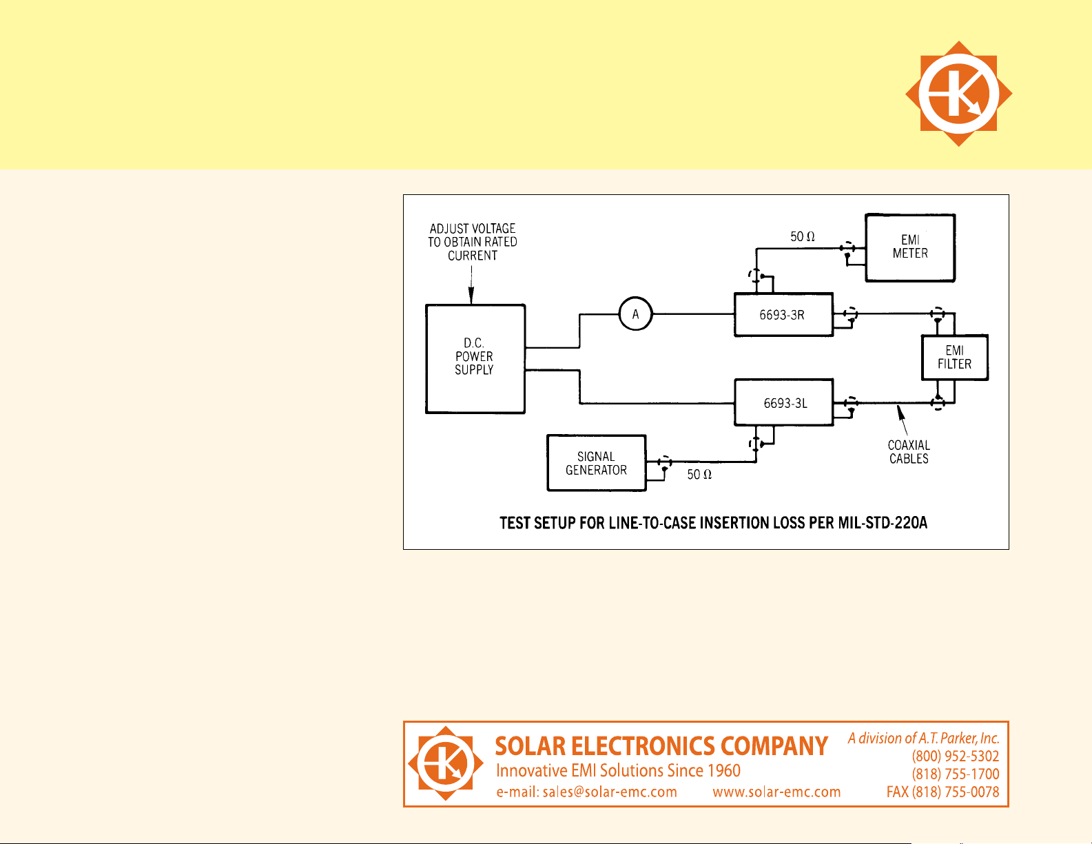
Two styles are used in the test setup as shown in
the diagram on this page.The two units, 6693-3L
and 6693-3R, are identical except that one is
physically the mirror image of the other for
convenience in making the test setup. Although
the jack on one side of one is marked SIGNAL
GENERATOR and the jack on the opposite side of
the other unit is marked R.F. VOLTMETER, these
two connections can be interchanged if it makes
your setup easier to use.
The shielded cable connection between the
connector marked TO FILTER UNDER TEST and the
filter is a matter which must be arranged to fit the
particular terminal or connector on the filter.
There are many different configurations and no
“standard” is possible. Ideally, the shield should
terminate in a metallic fitting which completely
shrouds the filter terminal, to avoid inadvertent
coupling at the higher frequencies.
Application Information
TYPE 6693-3L/3R RF-DC ISOLATOR NETWORK
FOR INSERTION LOSS TEST OF EMI FILTERS WITH D.C. CURRENT FLOWING THROUGH THE FILTER
75
 Loading...