

Page 1
PROGRAMMABLE AC/DC ELECTRONIC LOAD
MODEL 63800 SERIES
Ch ro ma 's 638 00 Se ri es A C/ DC El ec tr on ic
Loads are designed for testing uninterruptible
po wer supp li es( UP S), Off-Gr id Inv erter s,
AC sources and other powe r de vices such
as s wit che s, circ uit b rea ker s, fuse s and
connectors.
The Chroma 63800 Loads can simulate load
conditions under high crest factor and varying
power factors wi th real time compensation
even when the voltage waveform is distorted.
Th i s spec i al f eat u re p rov i des rea l wor ld
si mul ati on capa bi lit y an d prev ent s over -
stressing thereby giving reliable and unbiased
test results.
The 63800's state of the art designed us es
DSP technology to simulate non-linear rectified
loa ds in a un i que R LC op era t ion m ode .
This mode improves st ab il it y by detectin g
the impedance of the UUT and dynamically
ad justi ng the load' s con tro l ban dw idt h to
ensure system stability.
Com prehensive measurement s allow users
to m onitor the outpu t pe rformance of UUT.
Additionally, voltag e & curr ent si gnals can
be routed to an oscilloscope through analog
out p u t s. Th e ins t r u ment ' s GPI B / R S23 2
inter face opti ons pr ovide remote contro l &
monitor for syst em integration. In addition,
built-in digital outputs may be used to control
ex te rnal relay s f or short circuit (cr ow ba r)
testing.
Chroma's 63800 Loads also feature fan speed
co ntr ol ens ur ing low acou st ic n oise. Th e
diagnosis/p rotection funct ions in clude self-
diagnosis routines and protection against over-
power, over-current, over-voltage and over-
temperature.
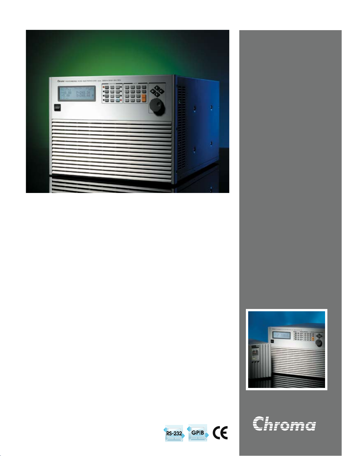
Programmable
AC/DC Electronic load
MODEL 63800 SERIES
Key Features :
■ Power Rating : 1800W, 3600W, 4500W
■ Voltage Range : 50V - 350Vrms
■ Current Range : Up to 18Arms, 45Arms
■ Peak Current : Up to 54A, 135A
■ Parallel / 3-Phase Function
■ Frequency Range : 45 to 440Hz, DC
■ Crest Factor Range : 1.414 to 5.0
■ Power Factor Range : 0 to 1 lead or
lag (Rectified mode)
■ CC, CR, CV, CP for DC Loading
■ Constant & Rectified Load Modes
for AC Loading
■ Analog Voltage & Current Monitor
■ Timing Measurement for Battery,
UPS, Fuse and Breaker tests
■ Measurement : V, I, PF, CF, P, Q,
S, F, R, Ip-/+ and THDv
■ Short circuit simulation
■ Full Protection : OP, OC, OV and
OT protection
■ GPIB & RS-232 interfaces
Page 2
Complete AC & DC Load Simulations
Chroma's 63800 AC/DC Electronic Load is designed for both AC & DC Load Simulations. Illustrated below are the various load modes
which are available:
Model 63800
AC Load Simulation DC Load Simulation
Constant Load Modes
Rectified Load Modes
CR Mode
CC Mode
CC Mode
RLC Mode
CV Mode
CR Mode
CP Mode
CP Mode
CP Mode
Inrush Mode
Rectified Mode
AC Load Simulation
The Model 63800 AC/DC Electronic Load provides two unique operating modes for AC load simulation; (1) Constant Load Modes and
(2) Rectified AC Load Modes. Each are described below.
Constant Load Modes
The Constant Load Modes allow users to set the following operating
modes : CC, CR and CP mode. The CC & CP modes in this category
allow users to program PF or CF, or both. For CR mode the PF is
always set to 1.
When both the PF & CF of the loading current are programmed,
the 63800 load controls power factor from 1 to 0 by shifting the
current (with CF defined) relative to the input voltage to get desired
displacement power factor. The power factor range will be limited
based on crest factor programmed. If the programmed PF is positive
then the current will lead the voltage waveform, in opposite, when PF
is set negative, the current will then leg the voltage waveform. (See
below)
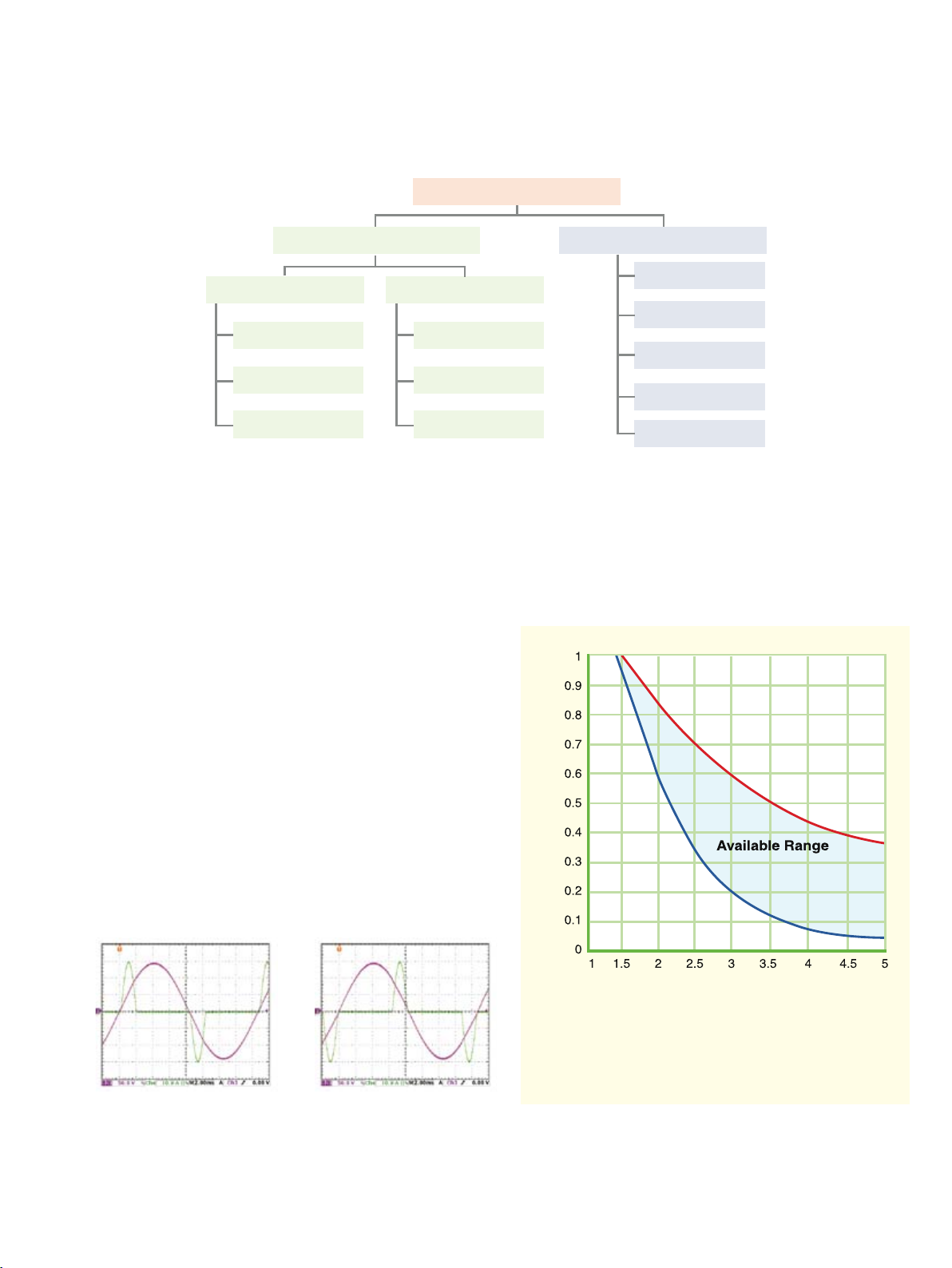
PF
CF
I
Figure 1: Crest Factor vs. Power Factor control Range
CFI = I peak / I rms
PF = True power / Apparent power
As seen in Figure 1, for a crest factor of 1.414, the programmed power factor can only be 1 if the input voltage is sine-wave. However, for a CF
of 2.0, the acceptable PF ranges from 0.608 to 0.85; for CF = 3, the PF can then be set from 0.211 to 0.6, etc. So, higher crest factors enable
wider range of power factors.
Page 3
Rectified AC Load Modes
The 63800 AC/DC Electronic Load provides unique capability to simulate
non-linear rectified loads for a wide range of testing applications. There
are three load modes available for rectified load simulations-RLC, CP and
Inrush Current modes.
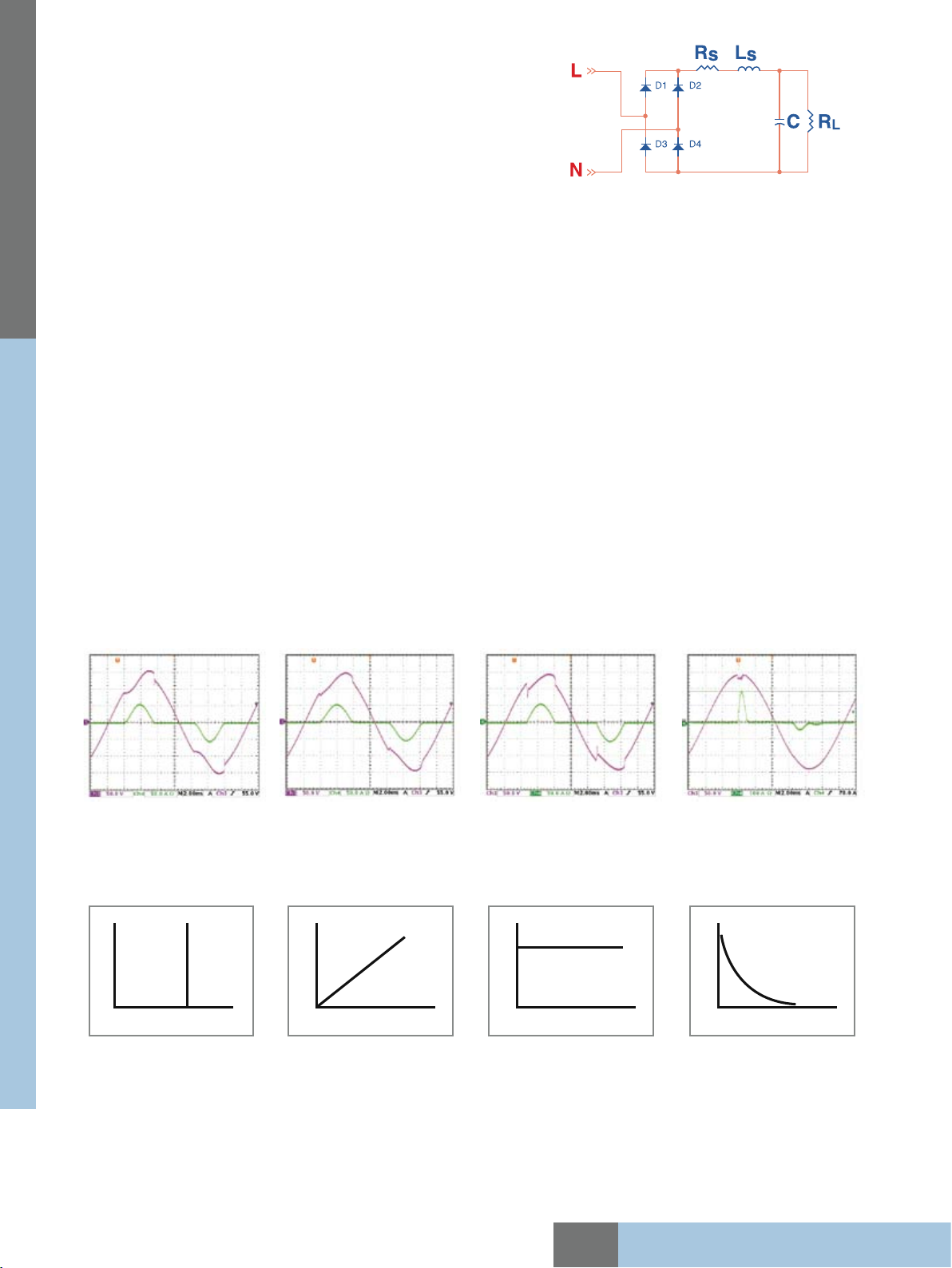
Figure 2 : Typical Rectified Circuit
Figure 2 shows the typical model of an rectifier input. Under RLC mode, users can set the RLC values to 100% simulate the behavior of
actual UUT. Figure 3 & 4 compares the voltage and loading waveforms between the actual RLC built circuit and the simulated rectified
circuit by using Chroma RLC load mode. The waveform of the 63800 in RLC mode looks almost identical to the waveform of actual
hardware circuit. The waveform obtained under CC mode with same loading crest factor shown in Figure 5 looks far from the waveform
of actual hardware circuit.
PROGRAMMABLE AC/DC ELECTRONIC LOAD
In addition, traditional AC loads can only use CR mode to test discontinuous square or quasi-square wave UUTs because CC and CP
are all active loadings and requires a defined frequency. It's very difficult to detect the frequency of a discontinuous square or quasi-
square wave. Since RLC mode of the 63800 load is actually simulating passive loading it doesn't require a defined frequency, therefore
it allows the user to simulate loading in modes other than just CR. Using discrete RLC network may solve the problem too, however
due to component weight, size and limited RLC values this makes it inconvenient for testing. In contrast, Chroma's 63800 RLC mode
provides versatile settings and higher test flexibilities.
For production line testing, most of users may not know their required RLC values but likely know the UUTs power rating and PF
values. In this case, CP mode is ideal for test engineers. Under CP mode, the 63800 built-in algorithm will find the best solution to get
the RLC values automatically according to the power rating and PF value set by the user.
To avoid overstressing the UUT, both the RLC and CP modes will gradually increase the loading current up to the programmed loading
current shown in Figure 4, simulating actual RLC circuit loading as shown in Figure 3. This will alleviate the sudden voltage drop from
constant current loading mode as shown in Figure 5.
For one that wishes to simulate the inrush current, the 63800 provides Inrush Current mode, allowing users to set different inrush
current amplitude and the voltage phase angle where the inrush current started.
Figure 3: Actual RLC Circuit Figure 4: Simulated RLC Mode Figure 5: CC Mode Figure 6: Inrush Current Mode
DC Load Simulation
Chroma's 63800 DC load simulation includes four load modes : constant current, constant resistance, constant voltage and
constant power as depicted below.
V
I
Constant current Constant resistance Constant voltage Constant power
CC, CR, CP mode can be used for regulated voltage power supplies testing. For battery charger, CV mode may help to check its
current regulation.
A special DC Rectified mode is included to simulate the loading behavior of Distributed Inverters. Many inverter designs, although
its input is DC, the input current will show rectified pattern. This unique load mode makes Chroma 63800 load ideal for Fuel Cell, PV
module/array and Battery test because those devices will be loaded by Inverters.
V
I
V
I
V
I
All specifications are subject to change without notice.
Model 63800 Series
Page 4
Comprehensive Measurements
Ch ro ma's 638 00 Series AC /D C Ele ct ronic Loads inc lu de s bui lt -in 16- bits pre ci sion
measurement circuits to measure the steady-state and transient responses for true RMS
voltage, true RMS current, true power(P), apparent power(S), reactive power(Q), crest factor,
power factor, THDv and peak repetitive current.
In additional to these discrete measurements, two analog outputs, one for voltage and one
for current, are provided as a convenient means of monitoring these signals via an external
oscilloscope.
Timing Measurement
Timing parameters are critical to many products such as UPS, Breaker and Fuse. The 63800 AC/DC Load also includes unique timing
measurement function to measure the trip time of fuse & circuit breaker or the transfer time for UPS (Off-Line).
Figure 7:
Transfer time for Off-Line UPS
Automatic Bandwidth Adjustment (ABA)
When using active load mode (CC,CP), traditional AC loads operate under fixed bandwidth. When the load is working at low control
bandwidth will limit the load from simulating high crest factor loading. In opposite, increase control bandwidth will influence the control
loop stability especially when the UUT output impedance is high. To resolve this problem in traditional AC load, Chroma 63800 AC/DC
Load dynamically adjusts the operating bandwidth by detecting the impedance*¹ of the UUTs to alleviate the risk of system instability.
The examples on the right compare voltage and current
waveforms using traditional fixed bandwidth (@15kHz)
loa d an d th e Ch r oma 6 380 0 loa d f or UPS load
simulation. Noticeable difference can be observed with
or without the ABA.
When the UUT has higher output impedance such as
Generator, the current waveform won't be stable as
shown below without ABA. In most cases, the loading
current will be oscillating and spoil the test.
Figure 8: Fixed Bandwidth Figure 9: With ABA
Note 1: A test current will be programmed prior the actual loading defined by user for impedance detection.
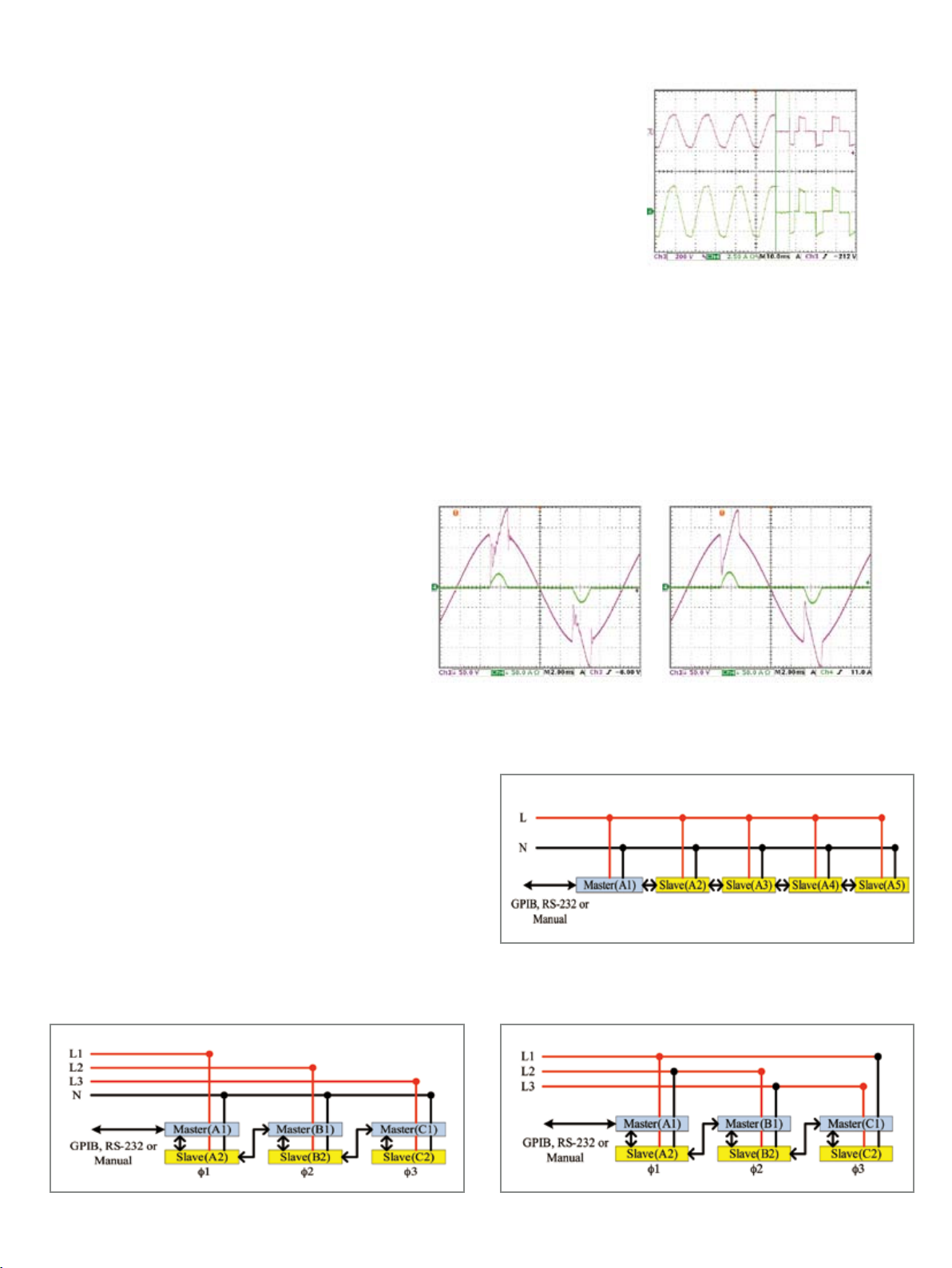
Parallel / 3-Phase Control
The 63800 series provides parallel and 3-phase functions for
high power and three phase applications. All the models within
the 63800 series can be used together for both parallel and
3-phase functions as well as paralleled AC Load units in 3-phase
configuration, providing excellent flexibility and cost savings for
the 63800 series AC load. Parallel and 3-phase controls are
made easy by linking the AC Load units together, control of all
AC load units will be made through the Master Unit. Connections
of parallel and 3-phase functions are as shown in Figures 11, 12
and 13.
Figure 11: Parallel/3-Phase Y connection Figure 12: Parallel/3-Phase Delta connection
Figure 10: Parallel connection
Page 5
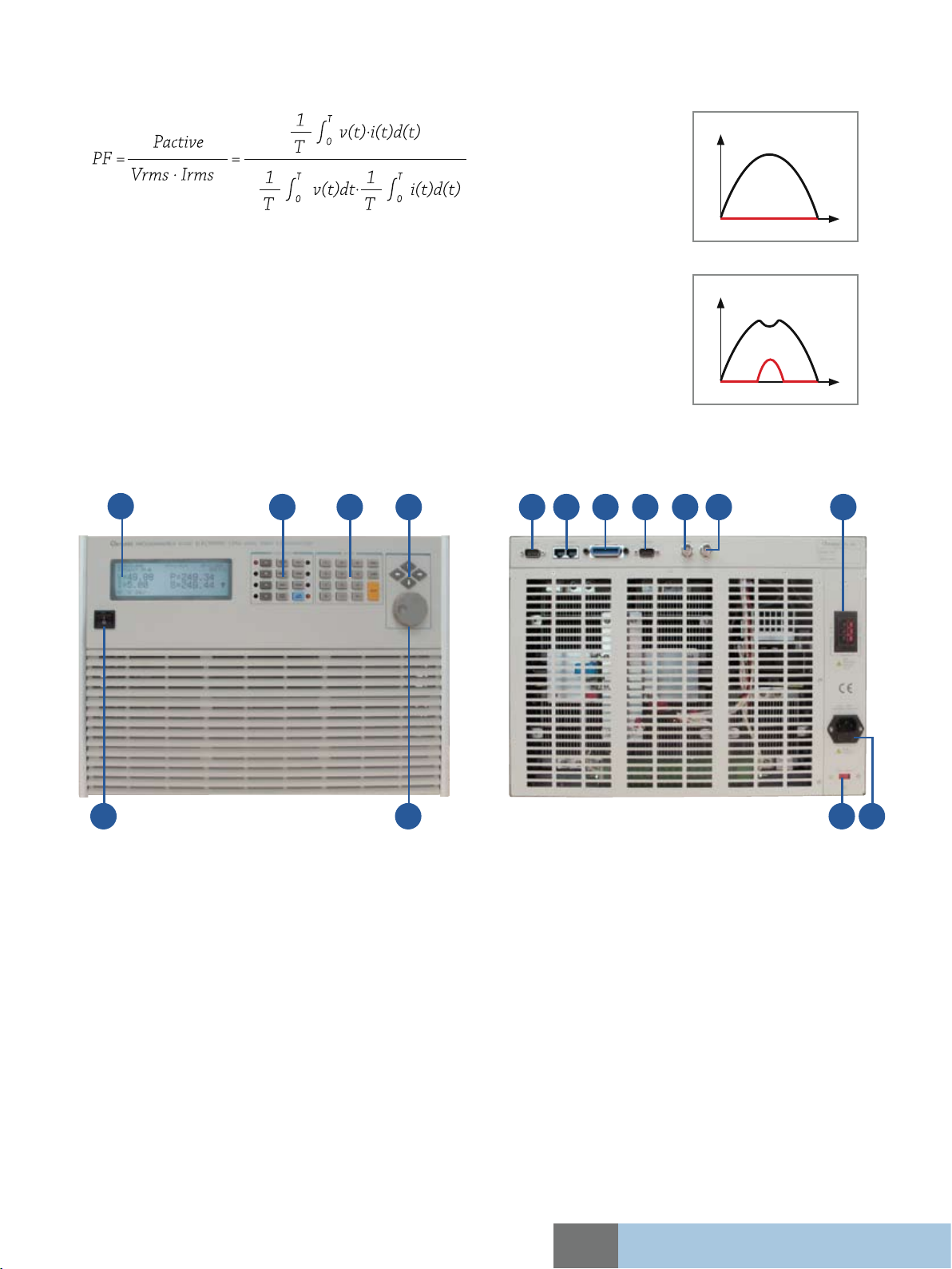
Auto Power Factor Correction
Allowing user to set the power factor is one of the major features to the 63800. The power factor is defined as :
Since PF is a function of real time voltage and current, traditional AC load designs assumes the voltage
waveform to be sinusoidal all the time, as seen Figure 11. This is not realistic because the voltage
waveform may be distorted after the load is applied shown in Figure 12, if the control of power factor
is base on the belief of sinusoidal voltage waveform, it will result in a lower power factor than the user
programmed thus overstressing the UUT.
Chroma's 63800 AC loads monitor the power factor reading constantly and uses this data to dynamically
adjust the loading waveform. As a result, the power factor setting is precise without overstressing the
UUT.
Panel Overview
1 2 3 4
7158 9
Figure 13
Figure 14
13121110
5 6
1. LCD display
2. Function keypad :
To select load mode, control mode, and system
config setting
3. Numeric keypad :
For data setting
4. Cursor key :
For setting and editing
5. Power switch
6. Rotary knob :
For rapid control of active parameter
7. TTL I/O :
For system input/output control signal
Ordering Information
63802 : Programmable AC Electronic Load 1800W/18A/350V
63803 : Programmable AC Electronic Load 3600W/36A/350V
63804 : Programmable AC Electronic Load 4500W/45A/350V
Model 63800 Series
14
8. System bus :
For master/slave control system data communication
9. GPIB connector
10. RS-232 connector
11. Voltage monitor output :
Analog output proportional to voltage waveform
12. Current monitor output :
Analog output proportional to the current waveform
13. Load terminal & Voltage sense terminal
14. AC input connector
15. AC input voltage switch
All specifications are subject to change without notice.
Page 6

Specifications
Model 63802 63803 63804
Power
Current
Voltage
Frequency
AC Section
Constant Current Mode
Range 0 to 18Arms, Programmable 0 to 36Arms, Programmable 0 to 45Arms, Programmable
Accuracy 0.1% + 0.2%F.S. 0.1% + 0.2%F.S. 0.1% + 0.2%F.S.
Resloution 2mA 2mA 5mA
Constant Resistance Mode
Range 2.77Ω ~ 2.5kΩ, Programmable 1.39Ω~2.5kΩ 1.11Ω~2.5kΩ
Accuracy 0.5% + 0.5%F.S. 0.5% + 0.5%F.S. 0.5% + 0.5%F.S.
Resloution 20µ mho 20µ mho 50µ mho
Constant Power Mode
Range 1800W, Programmable 3600W, Programmable 4500W, Programmable
Accuracy 0.5% + 0.5%F.S. 0.2% + 0.3%F.S. 0.2% + 0.3%F.S.
Resloution 20µ mho 0.375W 1.125W
Crest Factor (under CC, CP modes)
Range 1.414 to 5.0, Programmable 1.414 to 5.0, Programmable 1.414 to 5.0, Programmable
Accuracy (0.5% / Irms) + 1% F.S. 1%F.S. + (0.5%/Irms) 1%F.S. + (0.5%/Irms)
Resloution 0.005 0.005 0.005
Power Factor
Range 0 to 1 lead or lag, Programmable 0 to 1 lead or lag, Programmable 0 to 1 lead or lag,Programmable
Accuracy 1%F.S. 1%F.S. 1%F.S.
Resloution 0.001 0.001 0.001
Rectified Load Mode
Operating Frequency 45Hz~70Hz
RLC Mode Parameter : Ip(max), Rs, Ls, C, R
Constant Power Mode Parameter : Ip(max), Power setting=200W to 4500W, PF=0.4 to 0.75
Inrush Current Mode
Rs Range 0 to 9.999Ω 0 to 9.999Ω 0 to 9.999Ω
Ls Range 0 to 9999µH 0 to 9999µH 0 to 9999µH
C Range 100 to 9999µF 100 to 9999µF 100 to 9999µF
RL Range 2.77 to 9999.99Ω 1.39 to 9999.99Ω 1.11 to 9999.99Ω
DC Section
Voltage Range 7.5V to 500V 7.5V to 500V 7.5V to 500V
Current Range 0A to 18A 0A to 36A 0A to 45A
Min. operating voltage 7.5V 7.5V 7.5V
Rise time 75µs 75µs 75µs
Operating Mode CC, CV, CR, CP, DC Rectified
Short Circuit Simulation Use the CR mode loading under max. power rating
Measurement Section
DVM Range 500.0V 500.0V 500.0V
DVM Accuracy 0.1% + 0.1%F.S. 0.1% + 0.1%F.S. 0.1% + 0.1%F.S.
DVM Resloution 10mV 10mV 10mV
DAM Range 80.00A 200.00A 200.00A
DAM Accuracy(<70Hz) 0.1% + 0.2%F.S. 0.1% + 0.2%F.S. 0.1% + 0.2%F.S.
DAM Accuracy(>70Hz) 0.1% + 0.2%F.S. + 0.1% x CF² x kHz 0.1% + 0.2%F.S. + 0.1% x CF² x kHz 0.1% + 0.2%F.S. + 0.1% x CF² x kHz
DAM Resloution 1.0mA 2.5mA 2.5mA
Other Parameter P(W), S(VA), Q(VAR), CF, PF, Freq, R, Ip-, Ip+, THDv
Others
Vmonitor ±500V / ±10V (Isolated) ±500V / ±10V (Isolated) ±500V / ±10V (Isolated)
Imonitor ±80A / ±10V (Isolated) ±200A / ±10V (Isolated) ±200A / ±10V (Isolated)
OCP : 19.2Arms ; OVP : 360Vrms
Protection
Remote Interface GPIB, RS-232 or analog control
Line Voltage 115/230 Vac±15%
Dimension ( H x W x D)
Weight 34kg / 74.89lbs 60 kg / 132.16 lbs 60 kg / 132.16 lbs
All specifications are subject to change without notice.
Developed and Manufactured by :
CHROMA ATE INC.
致茂電子股份有限公司
HEADQUARTERS
66, Hwaya 1st Rd., Hwaya Technology Park,
Taoyuan 333, Taiwan
Tel: +886-3-327-9999
Fax: +886-3-327-8898
http://www.chromaate.com
E-mail: chroma@chroma.com.tw
U.S.A.
CHROMA ATE INC. (U.S.A.)
7 Chrysler Irvine, CA 92618
Tel: +1-949-421-0355
Fax: +1-949-421-0353
Toll Free: +1-800-478-2026
1800W 3600W 4500W
0 ~ 18Arms (54 Apeak) 0 to 36Arms (108Apeak, continue) 0 to 45Arms (135Apeak, continue)
50 ~ 350Vrms (500 Vpeak) 50 to 350Vrms (500Vpeak) 50 to 350Vrms (500Vpeak)
45 to 440Hz, DC 45 to 440Hz, DC 45 to 440Hz, DC
L
Parameter : Ip(max), Rs, Ls, C, RL, Phase
80A (peak current) 160A (peak current) 200A (peak current)
(DC : 510VDC)
OPP : 1920W ; OTP
177 x 430 x 585 mm /
7.0 x 17.0 x 23.0 inch
OCP : 38.4Arms ; OVP : 360Vrms
(DC : 510VDC)
OPP : 3840W ; OTP
177 x 440 x 585 mm /
7.0 x 17.3 x 23.2 inch
OCP : 48Arms ; OVP : 360Vrms
(DC : 510VDC)
OPP : 4800W ; OTP
310 x 440 x 585 mm /
12.2 x 17.3 x 23.2 inch
Distributed by:
JAPAN
CHROMA JAPAN CORP.
4-20-7 Nishikoizumi, Oizumi,
Oragun, Gunma 370-0517,
Japan
Tel: +81-2-7661-0548
EUROPE
CHROMA ATE EUROPE B.V.
Morsestraat 32, 6716 AH Ede,
The Netherlands
Tel: +31-318-648282
Fax: +31-318-648288
CHINA
CHROMA ELECTRONICS
(SHENZHEN) CO., LTD.
8F, No.4, Nanyou Tian An
Industrial Estate, Shenzhen,
China PC: 518054
Tel: +86-755-2664-4598
Fax: +86-755-2641-9620
Worldwide Distribution and Service Network
63800-200902-PDF
 Loading...